
K-WANG


Schneider ELAU PacDrive C400/C400 A8 Controller
Schneider ELAU PacDrive C400/C400 A8 Controller
Product core positioning and system architecture
1. Core positioning
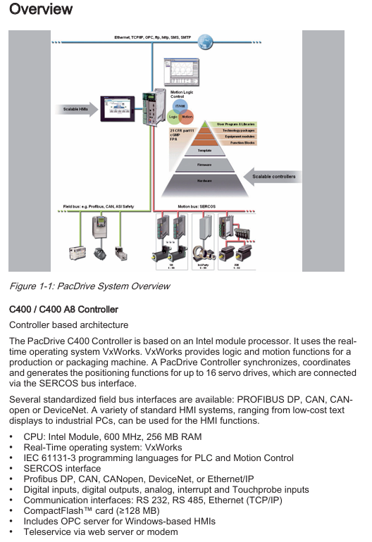
The PacDrive C400/C400 A8 is a high-performance motion controller based on a real-time operating system, designed specifically for industrial equipment that requires multi axis synchronization and precise positioning. Its core function is to coordinate servo drives to complete complex motion control tasks (such as cam synchronization, electronic gears, and multi axis interpolation), while supporting logic control and industrial communication, and adapting to automated production lines such as packaging, printing, and assembly.
2. System architecture
Hardware Core: Equipped with Intel processors (C400 for Pentium M 600MHz, C400 A8 for Celeron M 600MHz), 256MB RAM, 128kB NVRAM, and ≥ 128MB CompactFlash card (for program storage and data backup), ensuring real-time computation and data stability.
Real time operating system: Equipped with VxWorks real-time system, it has fast response speed, supports multitasking parallel processing, and meets the demand for "microsecond level" real-time performance in motion control.
Core bus: Connected to servo drives through SERCOS real-time motion bus (C400 supports up to 16 SERCOS slave stations, C400 A8 supports up to 8), achieving multi axis synchronous control; Simultaneously equipped with fieldbus such as PROFIBUS DP and CANopen, balancing logic control and device interconnection.
Core functions and technical features
1. Motor control ability
Multi axis control: C400 supports 16 servo axes, and C400 A8 supports 8 servo axes. All axes are compatible with full cycle control of SERCOS bus (such as 1ms/2ms/4ms cycle), which can achieve complex movements such as electronic gear, electronic cam, and multi axis interpolation, meeting high-precision synchronization requirements (such as film traction and cutter synchronization of packaging machines).
Cam and sequence control: Supports up to 256 dynamic cam groups, and cam curves can be customized through software; Sequence control supports three modes of "continuous/cycle/event triggering", adapted to the step-by-step action logic of the production line (such as workstation switching on the assembly line).
Position detection and feedback: equipped with 1 SinCos main encoder interface and 1 incremental main encoder interface (X11), supporting external position feedback; Simultaneously providing 16 Touchprobe trigger inputs (X4) with a resolution of 100 μ s, it can achieve precise positioning capture (such as product positioning detection).
2. Logic control and I/O expansion
PLC function: Supports IEC 61131-3 standard programming language (instruction list IL, ladder diagram LD, function block diagram FBD, structured text ST, etc.), can simultaneously handle motion control and logic control tasks (such as equipment start stop, safety interlock, fault diagnosis); PLC instruction execution speed is fast, with only 7 μ s required for 1000 instructions and a fast task cycle of up to 250 μ s.
Local I/O configuration:
Digital input: 20 channels (DC 20-33V, supporting 1/5ms parameterized filtering), used for detecting sensor signals (such as photoelectric switches, limit switches).
Digital output: 16 channels (DC 20-30V, rated current 250mA per channel, short circuit protection), used to control actuators (such as solenoid valves, indicator lights).
Analog I/O: 2 analog inputs (-10~10V or 0~20mA, 12 bit resolution), 2 analog outputs (-10~10V, 12 bit resolution), compatible with analog devices such as pressure sensors and proportional valves.
Fast I/O: 4-channel interrupt input (X4, 0.1/1ms filtering), used to process high-speed trigger signals (such as emergency stop, safety door signals).
Scalability: Up to 128 digital inputs/outputs and 128 Touchprobe inputs can be expanded through the PacNet interface; Through PROFIBUS DP, 126 slave stations can be connected, with a maximum expansion of 3584 bytes of digital/analog I/O, meeting the signal acquisition and control requirements of large-scale production lines.
3. Industrial communication and data exchange
Communication interface:
Motion bus: SERCOS (16MBaud), used for connecting servo drives to achieve multi axis synchronization.
Fieldbus: PROFIBUS DP (master/slave mode, 12MBaud), CANopen, DeviceNet (adapter required), EtherNet/IP (optional hardware module required), supporting interconnection with PLC, HMI, sensors and other devices.
General communication: RS232 (COM1), RS485 (COM2), Ethernet (10/100Base-T, supporting TCP/IP), used for program download, data monitoring, and remote maintenance.
Data exchange and remote services:
Built in OPC server, supports real-time data access for Windows based HMI (such as Schneider Vijeo Designer), and realizes device status visualization.
Support remote services between web servers and modems, enabling device diagnostic information to be obtained through browsers or SMS (SMTP protocol), simplifying on-site maintenance.
Integrated data logger (27kB) and trajectory logger (8 channels, 1ms resolution), capable of recording fault information and motion curves for troubleshooting and process optimization.
Hardware specifications and environmental adaptability
1. Electrical and mechanical parameters
Category specific specifications
The power requirement is DC 24V (-15%~+25%), with a maximum current of 3A without UPS and 4.5A with UPS. The maximum power consumption is 85W
The protection level of the shell is IP20, suitable for installation inside the control cabinet; Pollution level 2, suitable for industrial dust environment
Size and weight: Packaging size 300 × 130 × 400mm (D × W × H), with packaging weight of 3.5kg (C400)/4.1kg (C400 A8)
Isolation and anti-interference comply with the IEC 61000-6-2 electromagnetic interference standard, supporting shielded cable connections to reduce signal interference
Diagnostic and monitoring alphanumeric diagnostic display screen, status LED indicator light; Watchdog function (maximum 60V/2A), triggers relay in case of malfunction
2. Environmental adaptability
Scene temperature range, humidity range, and other requirements
Normal operation+5 ℃~+45 ℃ (C400); +5 ℃~+40 ℃ (with UPS) 5%~85% RH (no condensation) No freezing or water ingress allowed
Transportation -25 ℃~+70 ℃ (C400); -25 ℃~+50 ℃ (with UPS) 5%~95% RH (without condensation) Prohibited from severe vibration (compliant with IEC 60721-3-2 2K3 level)
Long term storage (inside packaging) -25 ℃~+55 ℃ (C400); -5 ℃~+45 ℃ (with UPS) 5%~95% RH (no condensation) Prohibited corrosive gas environment
Interface configuration and wiring specifications
1. Core interface layout
The controller panel consists of 20 interfaces (X1~X20), and the core interface functions and wiring requirements are as follows:
Interface number, interface type, functional description, wiring specifications
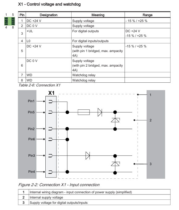
X1 control power supply/watchdog connected to DC 24V power supply, outputting watchdog relay signal; Shielded cable is required for terminal cross-sectional area of 1.5mm ² (AWG 16-28), and the positive and negative poles of the power supply should be distinguished
X2 digital output with 16 channels of DC 20-30V output, terminal cross-sectional area of 1.5mm ². The output terminal needs to be equipped with a fuse according to the load
X3 digital input with 20 channels of DC 20-33V input, terminal cross-sectional area of 1.5mm ². The input signal needs to match the sensor output type
X4 Touchprobe/Fast Input 16 Touchprobe inputs+4 Fast Interrupt inputs, with a terminal cross-sectional area of 1.5mm ². High speed signals require twisted pair shielded cables
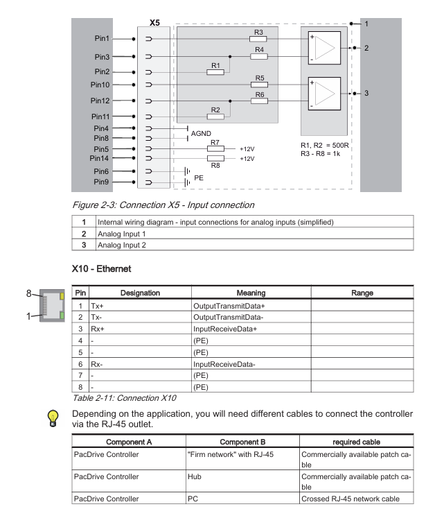
X5 analog I/O 2-channel analog input (-10~10V/0~20mA)+2-channel analog output (-10~10V), with a terminal cross-sectional area of 1.5mm ². Analog signals need to be wired separately to avoid interference
X10 Ethernet RJ45 interface (10/100Base-T), supports TCP/IP protocol for connecting HUB with direct Ethernet cable and connecting PC with crossover Ethernet cable
The X11 main encoder supports SinCos (+9V power supply) or incremental (+5V power supply) encoders, with a terminal cross-sectional area of 0.25mm ². The encoder signal needs to be twisted pair shielded to avoid noise
The X14/X15 SERCOS bus is connected to the real-time motion bus of the servo drive, supporting a 16MBaud rate and requiring the use of SERCOS dedicated shielded twisted pair cables
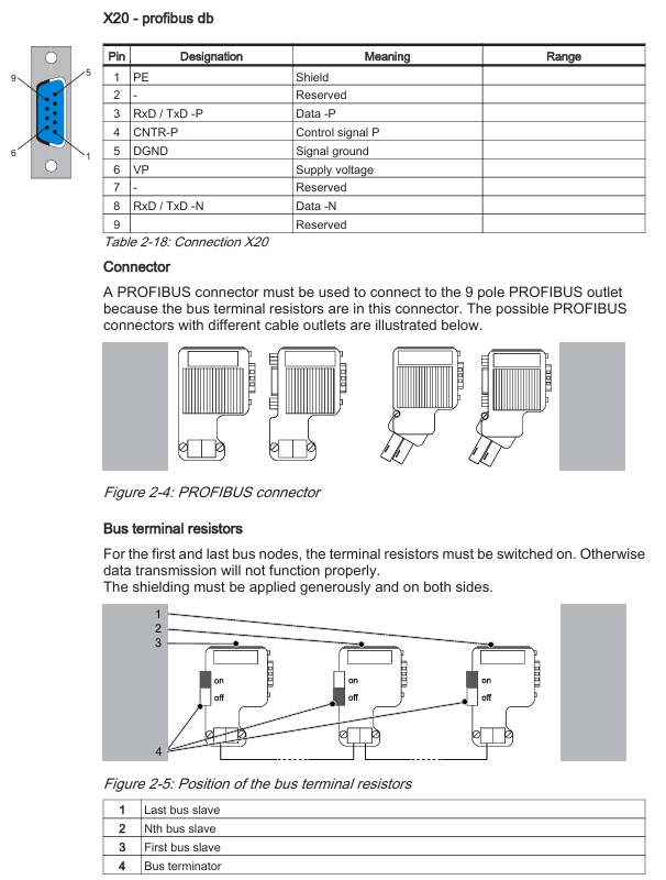
X20 PROFIBUS DP 9-pin D-type interface, master/slave mode, maximum 12MBaud rate requires the use of PROFIBUS dedicated connectors (with terminal resistors)
2. Wiring precautions
Power wiring: The DC 24V power supply of X1 interface needs to be supplied separately to avoid sharing the circuit with other high-power devices and prevent voltage fluctuations from affecting the stability of the controller.
Shielding treatment: All analog signals, encoder signals, and SERCOS bus cables need to be single ended grounded (on the control cabinet side), and the shielding layer should tightly wrap around the cable to reduce electromagnetic interference.
Bus terminal resistance: Terminal resistance (120 Ω) should be enabled at the beginning and end nodes of PROFIBUS DP and CAN bus to ensure the integrity of the bus signal; The intermediate node needs to turn off the terminal resistor.
Compliance certification
Safety and compliance certification
Safety certification: Complies with CE, UL, and cUL certification standards, and meets the industrial equipment safety requirements of the European Union (EN) and North America (UL).
Electromagnetic compatibility (EMC): Complies with IEC 61000-6-2 (anti-interference in industrial environments) and EN 55011 (radiation limits) standards, and can operate stably in strong electromagnetic environments such as high-voltage motors and frequency converters.
Environmental standards: Complies with the IEC/EN 60721-3 series standards and adapts to temperature and humidity changes in industrial settings.
Product Model and Selection
1. Model differentiation
Model Core Differences Order Number Applicable Scenarios
PacDrive C400 supports 16 SERCOS slaves, Pentium M processor 13130261 for multi axis complex motion scenes (such as 16 axis packaging machines)
The PacDrive C400 A8 supports 8 SERCOS slaves, and the Celeron M processor 13130261-001 is suitable for low to medium axis scenarios (such as 8-axis assembly lines)
2. Selection suggestions
Axis requirement: Select the number of servo axes according to the production line (C400 adaptation ≤ 16 axes, C400 A8 adaptation ≤ 8 axes), and reserve 1-2 spare axis positions for later expansion.
Function extension: If EtherNet/IP communication or UPS uninterruptible power supply is required, the corresponding optional module needs to be selected; If a large amount of I/O expansion is required, priority should be given to using PacNet or PROFIBUS DP expansion to avoid insufficient local I/O resources.
Environmental adaptation: If the temperature in the application scenario is below+5 ℃ or above+45 ℃, additional temperature control devices (such as control cabinet air conditioning) need to be configured to ensure that the controller operates within the rated temperature range.
- YOKOGAWA
- Reliance
- ADVANCED
- SEW
- ProSoft
- WATLOW
- Kongsberg
- FANUC
- VSD
- DCS
- PLC
- man-machine
- Covid-19
- Energy and Gender
- Energy Access
- Renewable Integration
- Energy Subsidies
- Energy and Water
- Net zero emission
- Energy Security
- Critical Minerals
- A-B
- petroleum
- Mine scale
- Sewage treatment
- cement
- architecture
- Industrial information
- New energy
- Automobile market
- electricity
- Construction site
- HIMA
- ABB
- Rockwell
- Schneider Modicon
- Siemens
- xYCOM
- Yaskawa
- Woodward
- BOSCH Rexroth
- MOOG
- General Electric
- American NI
- Rolls-Royce
- CTI
- Honeywell
- EMERSON
- MAN
- GE
- TRICONEX
- Control Wave
- ALSTOM
- AMAT
- STUDER
- KONGSBERG
- MOTOROLA
- DANAHER MOTION
- Bentley
- Galil
- EATON
- MOLEX
- Triconex
- DEIF
- B&W
- ZYGO
- Aerotech
- DANFOSS
- KOLLMORGEN
- Beijer
- Endress+Hauser
- schneider
- Foxboro
- KB
- REXROTH
- YAMAHA
- Johnson
- Westinghouse
- WAGO
- TOSHIBA
- TEKTRONIX
- BENDER
- BMCM
- SMC
- HITACHI
- HIRSCHMANN
- XP POWER
- Baldor
- Meggitt
- SHINKAWA
- Other Brands
- UniOP
- KUKA
- IBA
- Beckhoff
-
Basler Electric DECS-250-CN1SN1N Automatic Voltage Regulator for Generator Excitation Control
-
ADLINK CPCI-6860A - 51-31310-OB10 industrial motherboard CompactPCI SBC
-
ADLINK AmITX-SL-G-H110 - 51-7A104-0A30 Mini-ITX Industrial Motherboard
-
ADLINK PXI-2005-003 - CPCI Industrial PC Data Acquisition Card Multi-Function DAQ
-
ADLINK DININ-814M - 51-14032-0A3D SCSI-100P cable connection Interface Terminal Board
-
ADLINK CPCI-3920NA/C2D15/M1G - 3U CompactPCI Intel Core 2 Duo Single Board Computer
-
ADLINK PCIE-8560 - 51-18014-0A20 Communication Card High Speed DAQ
-
ADLINK PCI-C154+ - Motion Control Card 4-axis Motion Controller Board
-
ADLINK PCI-RTV24 - image capture card Analog Video Frame Grabber
-
ADLINK NuPRO-842LV/P - 51-41360-0B30 Industrial Motherboard CPU Board
-
ADLINK cBP-3208/3208R - CPCI Board 3U 8-Slot CompactPCI Backplane
-
ADLINK PCI-8164 - 4-Axis Motion Controller PCI Card 51-12406-0A40
-
ADLINK PCIe-GIE64+ - 4-CH GigE Vision PoE+ Frame Grabber Video Capture Card
-
ADLINK CPCI-6860 / 6860A - CompactPCI Dual Xeon Single Board Computer
-
ADLINK IEC-915GV - REV 1.1 Industrial motherboard CPU Board
-
ADLINK ND-6520 - Technology RS-232 to RS-422RS-485 Converter NuDAM Module
-
ADLINK RTV-24 / PCI-MP4S - 51-12519-1C30 4-Channel Real Time Video Capture Board
-
ADLINK cPCI-6910 / cPCI-6910AM/M1G - cPCI-6910AM/DXL16/M1G/S80G(G)-3120 BOARD CompactPCI SBC
-
ADLINK NUPRO-A40H - Linghua 51-41807-1A30 Industrial Control Computer Motherboard
-
ADLINK USB-3488A - USB to GPIB INTERFACE USB-3488A(G) Controller Module
-
ADLINK PCI-8134A - motion control card 4-Axis Controller Card
-
ADLINK PCI-7432 - Board 32-Channel input / 32-output Isolated Digital I/O PCI Card
-
ADLINK PCI-8134A - 51-12421-0A10 motion controller card tested
-
ADLINK LPCIe-7230 - 32 CH Isolated Input/output Card 2 Interrupts Low Profile PCIe
-
ADLINK NuPRO-E340 - industrial computer motherboard 51-47807-0A30 PICMG 1.3 SHB
-
ADLINK PCI-7434 - High-speed Digital Acquisition Card 64-CH Isolated DO Card
-
ADLINK NuPRO-E330 - 51-41805-0A20 Indsutrial Board SHB Single Board Computer
-
ADLINK PCI-7248 - OPTO-22 48 CHANNEL DIO DIGITAL TTL/DTL I/O 51-12006-0A40 GP
-
ADLINK PCI-8134 - Motion control card 4-Axis Controller Card
-
ADLINK AMP-208C - Movimiento Control Tarjeta 51-12420-1A20 W/Expansión & Breakout
-
ADLINK PCI-8164 - 51-12406-0A40 PCB Board 4-Axis Motion Controller Card
-
ADLINK DIN-68Y-SGII / DIN-68M-J3A - Terminal Board Connector Interface Block
-
ADLINK PCIe-7432 - Technology 51-18402-0A10 PCIe Card With High Input Range
-
ADLINK PCI-8144 / PCI-8144N - Motion control card 4-Axis Stepper Controller Card
-
ADLINK HSL-HUB3/REPEATER - HIGH SPEED LINK EXTENSION MODULES Distributed Hub Module
-
ADLINK ND-6017 - Data Logging + Acquisition 8CH A/D input Mod NuDAM Module
-
ADLINK LPCIe-7250 - data acquisition card Low Profile 8-CH Relay Output Card
-
ADLINK PCI-7432 - I/O card 64-CH Isolated Digital Input Output PCI Card
-
ADLINK IMB-M43H - industrial control computer motherboard Q87 Chip Micro-ATX
-
ADLINK MP-C154 - Motion control Card 4-Axis Motion Controller Board
-
ADLINK PCI-RTV24 - image capture card Video Frame Grabber Card
-
ADLINK PCI-7250 - 8-CH Relay Output & 8-CH Isolated DI Card
-
ADLINK PCI-6308V - 8-CH 12-Bit Isolated Analog Output PCI Card PCB-I-E-1148=6EX2
-
ADLINK PCI-7248 - capture card 48-CH Opto-22 Compatible DIO Card
-
ADLINK HSL-AI16A02-M-VV - Analog Input Output Distributed Module
-
ADLINK NuPRO-A301 - Rev:1.4 NUPRO-A301 PICMG Full-Size Single Board Computer
-
ADLINK PCI-6208V-GL - 8-CH Voltage Analog Output PCI Card
-
ADLINK PCI-8134A - 51-12421-0A10 4-Axis Motion Controller Card
-
ADLINK MNET-S23 - TECHNOLOGY MNET S23 - SERVO DRIVER CONTROL MODULE
-
ADLINK M-342 - ATX I3 I5 I7 Q67 Industrial Motherboard
-
ADLINK NUPRO-780 - Industrial Motherboard CPU Board PICMG SBC
-
ADLINK MP-C154 / MP-C152 - 4-Axis Motion Control Card Pulse-Train Controller
-
ADLINK NuPRO-935A/LV10B0 - Motherboard 51-41802-0A10 GP w/RAM Industrial Control Board
-
ADLINK MP-C154 - Motion control card 4-Axis Motion Controller Mainboard
-
ADLINK PCI-7250 - PCI Acquisition Card 8-CH Relay Output Isolated DI Card
-
ADLINK ACL-7124 - Technology Inc.24 DIO Card Digital Input Output Card
-
ADLINK PCI-8554 A2 - Timer/Counter Data Acquisition Card
-
ADLINK DIN-825-GP4 - Terminal Block Interface Board Breakout Module
-
ADLINK NuPR0-761 - REV:1.1 Industrial motherboard Full-Size PICMG SBC
-
ADLINK MXE-1401/M8G (G) - Matrix Fanless Embedded Computer Industrial PC
-
ADLINK HSL-DI16DO16-UD-NN - Digital 16 Channel I/O Mod Distributed I/O Module
-
ADLINK ND6520 - NUDAM INTELLIGENT DA&C MODULE RS232-RS-422/RS485 CONVERTOR
-
ADLINK NUPRO-761 - REV:1.1 Industrial Motherboard CPU Board
-
ADLINK AMP-208C - Motion Control Card 51-12420-1A20 DSP-based 8-axis
-
ADLINK NuPRO-A301REV 1.4 - with packaging industrial computer motherboard PICMG SBC
-
ADLINK PCM-9112+ - 51-12300-0A2 industrial motherboard Multi-Function DAQ PC/104 Module
-
ADLINK PCM-7250+ - 8-CH Relay Outputs & 8-CH Isolated DI Module PC/104
-
ADLINK PCI-RTV24 - Image capture card Analog Video Frame Grabber
-
ADLINK PCI-8134 - Motion Controller PCI Card 4-Axis Controller Board
-
ADLINK PCI-7432 - Isolated Digital I/O PCI Card
-
ADLINK PCI-8554 A2 - acquisition card Timer/Counter Card
-
ADLINK PCI-8132 - Rev.A2 2-Axis Servo & Stepper Motion Controller Card
-
ADLINK PCI-8132 - Data Acquisition card 2-Axis Motion Controller Card
-
ADLINK EBP-13E4 - 51-46703-0A30 Industrial Backplane Board Passive Backplane
-
ADLINK PCI-800L - Electronic Card Interface Controller Card
-
ADLINK PCIe-GIE72 - 51-18531-0A10 PCB Board GigE Vision Frame Grabber
-
ADLINK DAQ-2010(G)-OOBO - Simultaneous-Sampling Multi-Function DAQ Card
-
ADLINK PCI-9112 - REV.B1 Multifunction DAQ Card Data Acquisition Card
-
ADLINK PCI-7230 - 51-12003-DA60 32-CH Isolated Digital I/O Card
-
ADLINK PCI-7432 - Data Acquisition Card Isolated Digital I/O PCI Card
-
ADLINK ETX-AT-N270-18/LXE - 51-71111-0A20 ETX CPU Module Motherboard
-
ADLINK HSL-DI32-UD-N - DIGITAL INPUT 32 POINTS MODULE Distributed I/O
-
ADLINK AMP-204C - Motion Control card DSP-Based 4-Axis Advanced Controller
-
ADLINK MNET-4XMOG-0050 - Four-axis Motion Controller Distributed Motion Module
-
ADLINK AMP-204C - Motion control card DSP-Based 4-Axis Pulse-Train Controller
-
ADLINK PCI-7442 - Switch card 64-Channel Datalogging & Acquisition Card
-
ADLINK M-302 - Industrial control motherboard ATX PC Board
-
ADLINK NUPRO-852 / NUPRO-852LV - Industrial motherboard Single Board Computer
-
ADLINK PCI-8134 - REV.B1. 4-Axis Motion Controller Card
-
ADLINK PCI-GIE62 + - 51-18502-0A20 2-CH GigE Vision Frame Grabber PoE Card
-
ADLINK PCI-MPG24 - 51-12523-0B20 MPEG4 Card Video Compression Hardware
-
ADLINK HSL-TB32-M-DIN - 32-CH I/O TERMINAL W/ HSL-AI16AO2-M-VV MODULE
-
ADLINK PCI-M114-GL - PCB Ver 2.1 Motion Controller Axis Card
-
ADLINK IMB-M40H - SYM76996H61 motherboard Industrial Computer Mainboard
-
ADLINK NUPRO-A40H - 51-41807-1A20 industrial control motherboard H61 Chip
-
ADLINK PCI-M114-GL - Axis Card Data Acquisition Card PCB VER2.2 Motion Controller
-
ADLINK PCI-8134 - Motion Controller PCI Card 4-Axis Controller Board
-
ADLINK PCI-8102 - Motion control card 2-Axis Servo & Stepper Controller
-
ADLINK NuPRO-841REV:3.0 - motherboard Industrial Control PC Board
-
ADLINK HSL-TB32-U-DIN REV A1 - Breakout Terminal Board Field I/O Module
-
ADLINK AMP-204C - Motion Control card DSP-Based 4-Axis Pulse-Train Controller
-
ADLINK NUPRO-A40H - 51-41807-1A20 industrial control motherboard H61 PC Board
-
ADLINK PCI-6308A / PCI-6308V - 51-12202-0A50 Isolated Analog Output Card
-
ADLINK AMP-204C - DSP-Based 4-Axis Advanced Pulse-Train Motion Controller
-
ADLINK PCI-7434 - Technology 64-Channel Isolated Digital I/O PCI Cards
-
ADLINK CPCI-6840 / CPCI-6840V / PM16/M1G-12G0 - CompactPCI Single Board Computer CPU Module
-
ADLINK PCIE-GIE74 - Motherboard Video Capture Card 51-18531-0A10 Frame Grabber
-
ADLINK NuPRO-E330 - industrial computer equipment motherboard Control Mainboard
-
ADLINK AMP-208C / 51-12420-1A20 - Motion Control Card W/ Expansion & Breakout Board
-
ADLINK HPCI-14S12U - industrial computer baseboard Passive Backplane 14 Slots
-
ADLINK PCI-8164 - 4-Axis Motion Controller PCI Card W/ 1x Cable, 1x Breakout Box
-
ADLINK PCIe-RTV24 - 51-18016-0A20 Image Acquisition Video Capture Card
-
ADLINK M-342 - 5 PCI ATX Motherboard Industrial PC Mainboard
-
ADLINK PCI-FIW64 - 4/2 Channel IEEE1394B Image Capture Card FireWire Frame Grabber
-
ADLINK PCI-7432 - digital IO card 64-CH Isolated Digital Input Output Card
-
ADLINK 51-12001-0C20 - Circuit Board PCI-7200 Data Acquisition Controller Card
-
ADLINK PXI-3920 - PXI 3U cPCI Industrial Controller Embedded System CPU Board
-
ADLINK NuPRO-841REV:2.0 - motherboard Industrial Control PC Board
-
ADLINK NuPro-E330 - 51-41805-0A20 PCB Industrial Control Computer Motherboard
-
ADLINK PCI-RTV24 - Image capture card Analog Video Frame Grabber
-
ADLINK PCI-7442 - Switch card 64-Channel Datalogging & Acquisition Card
-
ADLINK HPX-13S4 - device baseboard Passive Backplane Riser Card
-
ADLINK PCI-9112 REV A.1 - Multi Function DA&C Board Data Acquisition Card
-
ADLINK PCI-7248 - 51-12006-0A40 Card Control 48-CH Digital I/O Module
-
ADLINK CPCI-6860 / 6860A - motherboard CompactPCI Dual Xeon Single Board Computer
-
ADLINK DPAC-3020-11(G) - Embedded PC Automation Controller Machine Control Board
-
ADLINK NuPRO-841 REV:1.0 - industrial control motherboard CPU Board
-
ADLINK MNET-4XMOG-0050 - Four-axis Motion Controller MNET Motion Control Card

K-JIANG

Add: Jimei North Road, Jimei District, Xiamen, Fujian, China
Tell:+86-15305925923