
K-WANG


Watlow Anafaze CLS200 Series Controller
Watlow Anafaze CLS200 Series Controller
Product basic positioning and core advantages
1. Product positioning
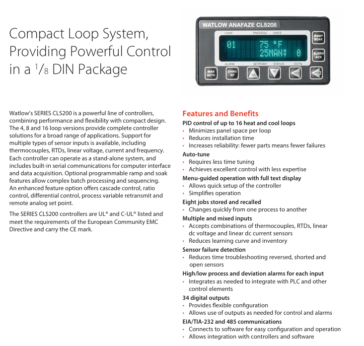
The CLS200 series is a compact loop control system designed in a 1/8 DIN package, offering three versions: 4-loop (CLS204), 8-loop (CLS208), and 16 loop (CLS216), which can cover multi scenario temperature control requirements (such as industrial heating/cooling control, batch processing, etc.). The device supports independent operation and can also be connected to a computer system through serial communication for data acquisition and remote control, in compliance with UL standards ®、 C-UL ® Certification and EU EMC directive, with CE mark.
2. Core advantages
Advantage categories, specific characteristics, and value
Space and efficiency: Single circuit occupies less panel space, supports multi circuit integration to reduce installation time, and reduces panel layout complexity
Easy to use Auto tune function; 32 character vacuum fluorescent display screen+8-key keyboard, menu guided operation reduces debugging threshold, precise control can be achieved without professional skills; Quickly complete parameter settings
Flexibility supports thermocouples RTD、 Multiple sensor inputs such as linear voltage/current, frequency, etc; 8 homework programs are stored and called to reduce spare parts inventory and learning costs, allowing for quick switching between different process flows
Reliability sensor fault detection (open circuit, short circuit, reverse connection); 34 digital outputs (50 pin terminal board configuration) shorten troubleshooting time and flexibly adapt to control and alarm requirements
Scalability supports EIA/TIA-232/485 serial communication; Optional DAC/SDA analog output module for easy integration with PLC and upper computer, meeting the requirements of analog signal conversion (such as process variable retransmission, motor speed regulation)
Core functions and firmware options
1. Basic control functions
PID control: Supports closed-loop PID control for up to 16 heating/cooling circuits, with 1-2 control outputs per circuit (supporting on/off time ratio and distributed zero crossing triggering).
Alarm function: Each input channel is equipped with independent process alarms (high/low limit) and deviation alarms, supporting user-defined dead zone, delay time, and startup suppression. The global alarm output can be linked to the PLC, and the watchdog output indicates the controller's operating status.
Data storage: capable of storing 8 job programs, supporting quick calling and switching of processes; The controller configuration can be imported/exported through the serial port.
2. Firmware version selection
Select firmware with different functions according to application requirements, and the core differences are as follows:
Firmware type, core functions, applicable scenarios
Standard firmware includes basic closed-loop PID, automatic tuning, alarm, job storage, sensor fault detection, and conventional temperature control scenarios such as constant temperature heating and simple cooling control
Ramp and Soak firmware includes standard functions+ramp heating/insulation control, process variable retransmission for complex batch processing (such as material aging testing, food processing, requiring staged temperature control)
Enhanced firmware includes standard functions+process variable retransmission, remote simulation set points, cascade control, proportional control, differential control, high-precision linkage control scenarios (such as multi loop coupling temperature control, remote set point adjustment)
Note: The serial control and remote simulation set point functions of the enhanced firmware require 2 controller channels to be occupied; Unused control outputs can be configured for process variable retransmission (with SDAC module).
Detailed explanation of technical parameters
1. Input parameters
(1) Analog input and sensor support
Input type, specific specifications, accuracy (25 ℃ environment)
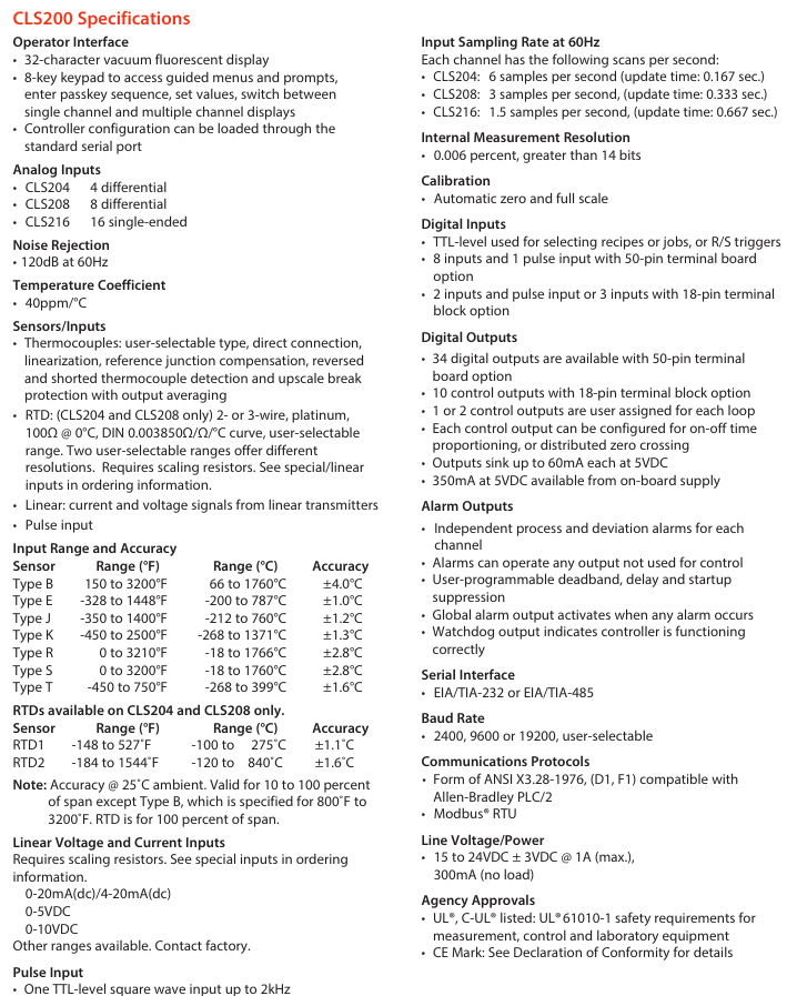
Thermocouples support Type B/E/J/K/R/S/T, direct connection, with cold junction compensation and linearization; Type B has a range of 66-1760 ℃, while other types have a range of -268~1371 ℃ (depending on the type) ± 1.0~4.0 ℃ (Type E has the highest accuracy and Type B has the lowest accuracy)
RTD (CLS204/208 only) 2/3 wire platinum resistance (100 Ω @ 0 ℃, DIN 0.003850 Ω/Ω/℃), divided into 2 ranges:
-RTD1: -100~275 ℃ (0.1 ℃ resolution)
-RTD2: -120~840 ℃ (1 ℃ resolution) ± 1.1 ℃ (RTD1), ± 1.6 ℃ (RTD2)
Linear input requires an external scaling resistor, supporting 0-20mA/4-20mA DC, 0-5V DC, 0-10V DC, and other ranges can be customized-
Pulse input TTL level square wave, up to 2kHz-
(2) Input performance
Noise suppression: 120dB at 60Hz; Temperature coefficient: 40ppm/℃;
Sampling rate: CLS204 (6 times/second, update time 0.167 seconds), CLS208 (3 times/second, 0.333 seconds), CLS216 (1.5 times/second, 0.667 seconds);
Measurement resolution:>14 bits (0.006% range).
2. Output parameters
Digital output: 34 outputs when configured with a 50 pin terminal board, 10 outputs when configured with an 18 pin terminal board, with a maximum sink current of 60mA (5V DC) per output. The onboard power supply provides 350mA (5V DC);
Analog output: No onboard analog output, requires optional module expansion (DAC/SDC).
3. Communication and Power Supply
Serial communication: EIA/TIA-232 or EIA/TIA-485, baud rates 2400/9600/19200 can be set, supports ANSI X3.28-1976 (compatible with Allen Bradley PLC/2), Modbus ® RTU protocol;
Power requirements: 15-24V DC ± 3V, maximum 1A (loaded), 300mA (unloaded), optional 120/240V AC to 15V DC adapter (UL) ® Class 2 certification).
Optional modules (DAC/SDC)
Used to convert the digital output of the controller into analog signals to meet specific control requirements:
Module type, functional specifications, application scenarios
DAC (Digital to Analog Converter) 1-2 distributed zero crossing trigger (DZC) outputs are converted into analog signals, each of which can be configured as 4-20mA DC, 0-5V DC, or 0-10V DC for simple analog signal conversion (such as valve opening control, ordinary speed regulation)
SDAC (Serial Digital to Analog Converter) 1 high-precision analog output (voltage/current), supporting process variable retransmission, open-loop control, motor/belt speed regulation, phase triggered SCR power control, with CE/UL ®/ C-UL ® Certification of high-precision signal requirements (such as precision instrument temperature control, remote monitoring of process variables)
Module power configuration
Power option specifications support module quantity
A has no power supply-
B 120V AC 60Hz wall mounted power supply (16V DC 300mA) with up to 10 dual DAC modules
H 120/240V AC 50/60Hz adapter (15V DC 1.2A) with up to 12 dual DAC modules
L 120/240V AC 50/60Hz adapter (5V DC 3A) with up to 10 SDAC modules
Ordering Rules and Selection Guide
1. Ordering code for the main controller (Series CLS200)
The code structure consists of 10 bits, and the key bits have the following meanings (see the document "Ordering Information" for the complete structure):
Code bit meaning optional values
② ③ Number of circuits: 04=4 circuits, 08=8 circuits, 16=16 circuits
④ Controller type (firmware) 1=standard, 3=slope insulation, 4=enhanced, C=customized
⑤ Terminal board 0=SCSI interface only, 1=18 pin terminal block (CLS204/208), 2=50 pin terminal block (including 3-foot SCSI cable)
⑥ Power adapter 0=none, 3=120/240V AC to 15V DC (UL) ® Class 2)
⑦ SCSI cable 0=none (option 0/1), 1=6-foot straight head, 2=3-foot elbow
⑧ Serial communication cable 0=none, 1=10 feet DB-9 female head/bare wire
⑨ Communication jumper 0=EIA/TIA-232, 1=EIA/TIA-485, 2=EIA/TIA-485 terminal matching
⑩ Special input 0/00=thermocouple only/-10~60mV, N/NN=current/voltage/RTD quantity (N is the quantity), XX=custom code
2. Special input selection (10 digits)
If you need to support RTD and linear current/voltage input, you need to specify a special input code:
Special input code type applicable to controllers
20 RTD1 (-100~275 ℃, 0.1 ℃ resolution) CLS204/208
21 RTD2 (-120~840 ℃, 1 ℃ resolution) CLS204/208
44 0-20mA/4-20mA DC Full Series
55 0-5V DC Full Series
56 0-10V DC Full Series
3. DAC/SDAC module ordering code
Code structure: CLSSI+special input type+start channel+end channel, for example, "CLSSI 44 01 04" represents 4-20mA input, covering 1-4 channels.
- YOKOGAWA
- Reliance
- ADVANCED
- SEW
- ProSoft
- WATLOW
- Kongsberg
- FANUC
- VSD
- DCS
- PLC
- man-machine
- Covid-19
- Energy and Gender
- Energy Access
- Renewable Integration
- Energy Subsidies
- Energy and Water
- Net zero emission
- Energy Security
- Critical Minerals
- A-B
- petroleum
- Mine scale
- Sewage treatment
- cement
- architecture
- Industrial information
- New energy
- Automobile market
- electricity
- Construction site
- HIMA
- ABB
- Rockwell
- Schneider Modicon
- Siemens
- xYCOM
- Yaskawa
- Woodward
- BOSCH Rexroth
- MOOG
- General Electric
- American NI
- Rolls-Royce
- CTI
- Honeywell
- EMERSON
- MAN
- GE
- TRICONEX
- Control Wave
- ALSTOM
- AMAT
- STUDER
- KONGSBERG
- MOTOROLA
- DANAHER MOTION
- Bentley
- Galil
- EATON
- MOLEX
- Triconex
- DEIF
- B&W
- ZYGO
- Aerotech
- DANFOSS
- KOLLMORGEN
- Beijer
- Endress+Hauser
- schneider
- Foxboro
- KB
- REXROTH
- YAMAHA
- Johnson
- Westinghouse
- WAGO
- TOSHIBA
- TEKTRONIX
- BENDER
- BMCM
- SMC
- HITACHI
- HIRSCHMANN
- XP POWER
- Baldor
- Meggitt
- SHINKAWA
- Other Brands
- UniOP
- KUKA
- IBA
- Beckhoff
- ADLINK
-
ADLINK HPCI-14S12U - Industrial Control Backplane 12PCI Backplane PCI-14S Passive Backplane
-
ADLINK PCIe-GIE74C - image acquisition card 4-CH GigE Vision PoE+ Frame Grabber
-
ADLINK PCI-8164 - control card 4-Axis Advanced Motion Controller Board
-
ADLINK PCIe-U304 - 4 Port USB3 PCIe Frame Grabbers USB Screw Hole Card
-
ADLINK PCI-9112 - Multi-Function Data Acquisition Card DAQ Card
-
ADLINK PCI-7432 - 51-12013-0A50 4-CH Isolated Numérique I/O PCI Cartes Digital I/O Card
-
ADLINK PCA-6106P3-0C1 REV.C1 - backplane 6-Slot Passive Backplane Board
-
ADLINK PCI-7224 - 24-CH Opto-Isolated Digital I/O PCI Board
-
ADLINK CPCI-7433R(G) - Digital Input Board Rear I/O CompactPCI Card
-
ADLINK EBP-13E4 - 51-46703-0A30 Industrial PC Backplane Passive Backplane
-
ADLINK PCIE-HDV62 - Image acquisition card High Definition Video Frame Grabber
-
ADLINK EBP-13E4 - 51-46703-0A30 Industrial Backplane Board Passive Backplane
-
ADLINK 90111-B1 / CPCI-6770 - PCB CPU MODULE CompactPCI Single Board Computer
-
ADLINK PCI-7248 - DATA ACQUISITION PCI CARD 48-CH Parallel Digital I/O Board
-
ADLINK PCI-7230 - 51-12003-0a50 board PCI7230 32-CH Isolated Digital I/O Card
-
ADLINK PCI2A000CB - 51-20000-0B30 Multi-Function DAQ Card Baseboard
-
ADLINK PCI-8134-005 - 4-Axis Motion Controller Card
-
ADLINK PCI-7224 - 24-CH Opto-Isolated Digital I/O PCI Card
-
ADLINK PCI-7434 - 64-CH Isolated Digital Output Card
-
ADLINK PCI-8132 - motion control card 2-Axis Servo & Stepper Controller
-
ADLINK PCI-8134 - Motion Controller PCI Card 4-Axis Controller Board
-
ADLINK PCI-8164 - Motion Control Card 51-12406-0A40 4-Axis Controller
-
ADLINK 51-12001-0C20 - Circuit Board Data Acquisition Interface Module Hardware
-
ADLINK NuPR0-840 - industrial control motherboard Full-Size PICMG CPU Board
-
ADLINK PCI-7444 - 51-12023-0A10 card 128-CH Isolated Digital Output Board
-
ADLINK PCI-1612B - data acquisition card 4-Port RS-232/422/485 Serial Communication Card
-
ADLINK PCI-6208V 009 - 8/16-CH 16-Bit Analog Output Cards PCB-I-E-482=6BX3
-
ADLINK NUPRO-935A/LV - industrial control motherboard Full-Size PICMG SBC Board
-
ADLINK PCI-9114DG - Multi-Function DAQ Card Data Acquisition PCI Card
-
ADLINK ACL-7130 - Data acquisition card Isolated Digital I/O Board
-
ADLINK ABX-6300D-4E1-BP - board ABX6300D4E1BP Video Interface Expansion Card
-
ADLINK CPCI-6940 - CPCI-6940/D1539/M16-0(EA)-000E 6U CompactPCI Processor Board
-
ADLINK NuPRO-760 - industrial control motherboard Half-Size PICMG SBC CPU Board
-
ADLINK IMB-M42H (G)-0020 - industrial control motherboard LGA1155 Micro-ATX Mainboard
-
ADLINK RTV-24 / PCI-MP4S - 51-12519-1C30 4-Channel Real Time Video Capture Board
-
ADLINK PCI-8134 - 4-Axis Servo & Stepper Motion Controller Card
-
ADLINK MXC-6101D - V.PC000.002.ST.00 Box PC Configurable Embedded Computer
-
ADLINK PCI-8134A - 51-12421-0A10 Motion Control Card 4-Axis Controller Card
-
ADLINK DIN-100S / DIN-100SA1 - Technology SCSI-II TB 100-PIN Terminal Block Board
-
ADLINK DIN-812M001 / DIN812M001 - 51-14034-0A1 51140340A1 Terminal Module Breakout Interface
-
ADLINK PCI-8164 - Servo motion control 4-Axis Advanced Controller Card
-
ADLINK PCIe-GIE64 - Acquisition card GigE Vision PoE+ Frame Grabber
-
ADLINK M-302 - Industrial control motherboard ATX PC Board Mainboard
-
ADLINK PCI-8134 - Motion Controller PCI Card 4-Axis Controller Board
-
ADLINK PCI-RTV24 - Image capture card Analog Video Frame Grabber
-
ADLINK PCI-8102 - Motion control card 2-Axis Servo & Stepper Controller Board
-
ADLINK PCI-9112 REV.B1 - Card Multi-Function Data Acquisition Card
-
ADLINK HSI-DI32-M-N / HSL-TB32-M-DIN - Discrete I/O MODULE Distributed Automation Module System
-
ADLINK PCI-7296 - IO card REV.A3 96-CH Parallel Digital I/O Card
-
ADLINK DIN-814P-A4 / 814Y - terminal board Motion Control Interface Block
-
ADLINK DIN-814P-A4 - 51-14056-0A10 PCB-I-E-2736=ZA01 Screw Terminal Board Breakout
-
ADLINK M-322 - motherboard Industrial Control Computer Mainboard
-
ADLINK NUPRO-406 REV:B1 - industrial control motherboard Full-Size PICMG CPU Board
-
ADLINK AMP-204C - card DSP-Based 4-Axis Advanced Pulse-Train Controller
-
ADLINK HPCI14S REV.B1 - industrial computer baseboard 14-Slot Passive Backplane
-
ADLINK PCI-7250 - 8-CH Relay Output & 8-CH Isolated DI PCI Card
-
ADLINK EBP-13E2 - baseplate Passive Backplane Industrial Computer Chassis Board
-
ADLINK LPCI-3488A - PCI-GPIB card 51-12801-0A30 acquisition card IEEE-488 Interface Board
-
ADLINK PCI-6216V-GL - 51-12201-0C30 16-CH 16-Bit Voltage Analog Output Card
-
ADLINK ACL-8454 - 16-CH Isolated Digital I/O & 4-CH Counter Card
-
ADLINK HPCI-9S7U - backplane Passive Backplane Compatible with NuPRO-A301 852 841 842
-
ADLINK DAQ-2010-007 - Simultaneous-Sampling Multi-Function Data Acquisition Card
-
ADLINK MP-C154 - 51-64205-0A10 Motion Control Card 4-Axis Controller Board
-
ADLINK MXE-202/mSSD16B/WiFi-BT - Matrix Rugged I/O Platform Embedded Fanless Computer
-
ADLINK CM-920-R-17 - PC/104-Plus Single Board Computer Module Intel Celeron M
-
ADLINK PCI-7250 NSMP - 8-CH Relay Output & 8-CH Isolated DI Card
-
ADLINK PCI-8164 - 4-Axis Motion Controller PCI Card W/ Cable and Breakout Box
-
ADLINK EMX-100 - Ethernet-based 4-axis Motion Controllers Distributed Motion Module
-
ADLINK PCI-8134A - Press control card 4-Axis Motion Controller Board
-
ADLINK M-845EG REV:3.2 - industrial motherboard Pentium 4 Socket 478 Micro-ATX
-
ADLINK PCI-9114A Rev A2 DG - card High-Resolution Multi-Function Data Acquisition Board
-
ADLINK IEC-915GV - REV 1.1 Industrial motherboard Socket 478 CPU Board
-
ADLINK PCI-9111DG(G) - Data Acquisition Card Multi-Function DAQ Card
-
ADLINK HPCI-15S10 REV:B2 - Industrial computer base plate Passive Backplane Board
-
ADLINK NuPR0-840 / NuPR0-840DV - industrial control motherboard Full-size PICMG CPU Board
-
ADLINK RTV-24 / PCI-MP4S - 51-12519-1C30 4-Channel Real Time Video Capture Board
-
ADLINK NUPRO-780 - industrial control motherboard Pentium III Single Board Computer
-
ADLINK PCI-7296 - 0050 card 96-CH Opto-Isolated Parallel DIO Card Set
-
ADLINK NUPRO-780 - industrial control motherboard PICMG Full-Size SBC
-
ADLINK PCI-7248 - 51-12006-0A3 002 Pci 7248 48-CH Parallel Digital I/O Card
-
ADLINK cPCI-6626 - 6U CompactPCI 2.0 Blades i7-2710QE PCB-I-E-2570=9N41
-
ADLINK MXC-6322D(G) - Industrial Fanless Computer
-
ADLINK cPCI-8168-004 - CompactPci NulPC Motion Control Board 51-36402-0A3
-
ADLINK CPCI-7300[G] - COMPACTPCI Digital I/O Card Data Acquisition
-
ADLINK CPCI-6626/2710/M4G - COMPACTPCI COMPUTER BOARD
-
ADLINK cPCI-8168-009 - cPCI NulPC Motion Control Board
-
ADLINK cPCI-6626/2710/M4G - VME CPU Board Computer Board
-
ADLINK CPCI-R6200(G)-0040 - COMPACTPCI CONTROL BOARD
-
ADLINK CPCI-3840/PM18/M1G(G)-3650 - COMPACTPCI CPU Module Single Board Computer
-
ADLINK cPCI-7248 - 48-CH Opto-22 Compatible Digital I/O Module
-
ADLINK DLAP-211-JNX - NVIDIA Jetson Xavier NX Edge AI Inference Platform
-
ADLINK cPCI-3544 - Series 4-Port RS-422/485 Isolated Serial Communications Card
-
ADLINK CM1-86DX3 - PC/104 SBC Stanley Vortex86DX3 CPU 2GB Ram
-
ADLINK DLAP-211-JNX - NVIDIA Jetson Xavier NX Edge AI Inference Platform
-
ADLINK cPCI-3544 - Series 4-Port RS-422/485 Isolated Serial Communications Card
-
ADLINK CM1-86DX3 - PC/104 SBC Stanley Vortex86DX3 CPU 2GB Ram
-
ADLINK PCI-7433 - switch value acquisition card Isolated Digital Input Card
-
ADLINK PCI-9112 - 51-12252-0D20 Multi-Function Data Acquisition Card
-
ADLINK NUPRO-A301 REV:1.4 - industrial control motherboard PICMG Full-Size SBC
-
ADLINK 51-18502-0A10 - Frame Grabber Image Acquisition Interface Card
-
ADLINK PCI-7296 - 51-12009-0A50 PCB-I-E-925=6DX1 96-CH Parallel Digital I/O Board
-
ADLINK PCI-8132 GP A2 - Motion Control Card 2-Axis Servo & Stepper Controller
-
ADLINK PCI-7442 - switch quantity card data acquisition card 64-CH Isolated Card
-
ADLINK HPX-13S4 - baseboard PICMG 1.3 Passive Backplane Chassis Baseplate
-
ADLINK NuPRO-590 / NTC-567-ZM-F36 - Single Board Computer PCB-I-E-1853=9L21 Half-Size SBC
-
ADLINK PCIe-8332 - 16-axis plate Motion Control Hardware Card
-
ADLINK NuPRO-775 REV.B1 - motherboard Pentium 4 Full-Size PICMG SBC
-
ADLINK PXI-3920 - Embedded Controller 3U PXI cPCI System Intelligence Board
-
ADLINK PCI-8134 - driver card motion control card 4-Axis Controller Board
-
ADLINK HSL-DI32-M-N-011 / HSL-TB32-M-DIN - Digital Input & Base Module PLC Distributed I/O System
-
ADLINK PCI-6216V-206 / PCI-208V 009 - 16 CH 16bit analog output card
-
ADLINK NuPro-E330 - 51-41805-0A20 PCB Single Board Computer Host Board
-
ADLINK PCI-1622C - Card 8-Port RS-232/422/485 PCI Serial Communication Board
-
ADLINK PCIe-7432 - 51-18402-0A10 Carte PCIe Avec Plage D'Entrée Élevée Isolated DIO Card
-
ADLINK PCI-7250 - PCI Acquisition Card 8-CH Relay Output Isolated DI Card
-
ADLINK PCI-7230 - 32-CH Isolated Digital I/O Card
-
ADLINK PCI-8164 - PCB 4-Axis Motion Controller Card
-
ADLINK PCI-7854 - Collection card High-Speed Link Distributed Motion Controller
-
ADLINK NuPRO-935A/LV - industrial control computer motherboard Full-Size PICMG SBC
-
ADLINK IMB-M40H - motherboard IH61-AA4 1155 LGA1155 Micro-ATX Mainboard
-
ADLINK PCI-7248 - Linhua 51-12006-0A40 48-CH Parallel Digital I/O Card
-
ADLINK HPCI-14S12U - Linhua industrial computer baseboard Passive Backplane
-
ADLINK PCI-8132 Rev.A2 - 2-Axis Servo & Stepper Motion Controller Card
-
ADLINK ACL-8111 - ISA card Multi-Function DAQ Card
-
ADLINK ACL-8111 - ISA card Multi-Function Data Acquisition Board
-
ADLINK PCI-7200 REV.A3 - Digital I/O card 12MB/s High-Speed Parallel Digital I/O
-
ADLINK PCI-7296 REV.A3 - 96-CH High-Density Opto-Isolated DIO Card
-
ADLINK PCI-7434 - 64-CH Isolated Digital Output Card

K-JIANG

Add: Jimei North Road, Jimei District, Xiamen, Fujian, China
Tell:+86-15305925923