

K-WANG


CyberPower UT650EG / UT850EG User’s Manual
CyberPower UT650EG / UT850EG User’s Manual
Core Security Directive (Must See)
To avoid fire, electric shock, or equipment damage, the following requirements must be strictly followed:
Installation environment: It can only be used in indoor temperature and humidity controlled environments (see technical parameters for specific range). It is forbidden to expose it to direct sunlight, heat sources (such as heaters and furnaces), do not cover the heat dissipation holes, and stay away from conductive pollutants.
Load limit: It is prohibited to connect non computer devices such as medical/life support equipment, microwave ovens, vacuum cleaners, etc; High power equipment such as laser printers, copiers, and shredders cannot be connected to battery powered sockets (which can easily overload and damage UPS).
Usage taboos: Do not allow liquids or foreign objects to enter the equipment, and do not place liquid containers around UPS; Power off before cleaning, and prohibit liquid or spray cleaners; Battery maintenance should be carried out by professionals and unauthorized personnel are prohibited from accessing it.
Emergency response: In case of emergency, press the "OFF" button and unplug the power cord to cut off the UPS power supply; If overload is detected, the device will sound a long beep alarm, power off and remove at least one load before restarting.
Equipment installation process
1. Open box inspection
The packaging box should contain:
Core components: UPS host (1 unit, UT650EG or UT850EG)
Accessories: User Manual (1 book), USB Data Cable (1 piece, only equipped with UT850EG)
2. Hardware installation steps
Battery charging: The device can be used directly after receiving it, but it is recommended to charge it for at least 8 hours (to offset the power loss during transportation and storage). Simply plug the UPS into an AC outlet (it can be charged in both on/off states).
Load connection: In the power-off state, connect the computer, monitor, and external data storage device to the "Battery Backup&Surge Protected Outlets" and disable high-power devices.
Power access: Insert the UPS plug into a grounded 2-hole 3-wire socket (wall plugs need to be protected by fuses or circuit breakers). Do not share the same circuit with high-power devices such as air conditioners and refrigerators, and try to avoid using extension cords.
Startup: Press the power switch, the power indicator light will turn on and the device will beep once, indicating successful startup.
Overload handling: If overload is detected, the device will sound a long alarm, and at least one load needs to be removed from the power supply. Wait for 10 seconds and confirm that the circuit breaker/fuse is normal before restarting.
Long term maintenance: To maintain the optimal condition of the battery, it is necessary to always connect the UPS to an AC socket; When storing for a long time, it is necessary to fully charge the battery and cover it for storage. Charge it every 3 months to extend the battery life.
Basic Operation Guide
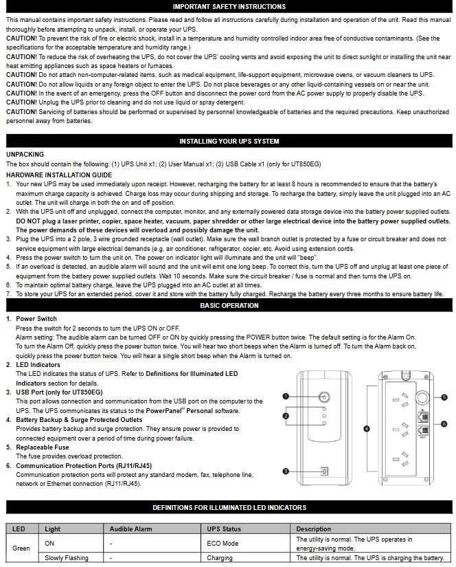
1. Core buttons and interface functions
Function Description of Operating Components
Press and hold the power switch for 2 seconds to turn on/off the device; Quickly press twice to turn on/off the sound alarm (default on, 2 short beeps when turning off the alarm, 1 short beep when turning on the alarm)
The LED indicator light displays the UPS status (such as normal mains power, battery charging, fault, etc., see the "LED Status Definition Table" for details)
USB interface (UT850EG only) connects to the computer's USB port through PowerPanel ® Personal software for UPS status communication and monitoring
The battery powered socket provides battery backup and surge protection, providing continuous power supply to the load during power outages
The replaceable fuse provides overload protection. If it melts due to overload, it needs to be replaced according to the specifications
Communication protection ports (RJ11/RJ45) protect modems, fax machines, telephone lines, and network/Ethernet connections from surge damage
2. Definition of LED indicator status
Different colors and flashing modes correspond to different device states, and the key explanation is as follows:
LED color, light status, sound alarm, UPS status, specific description
Green constant light - Energy saving mode (ECO): The mains power is normal, and the UPS is running in energy-saving mode
Green slow flashing - Battery charging is normal, UPS is charging the battery
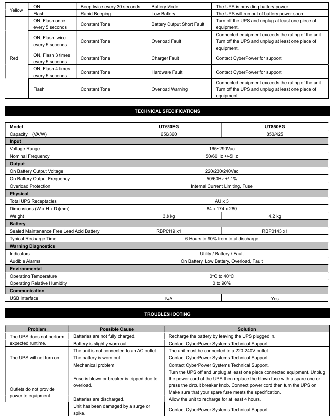
The yellow light stays on and beeps twice every 30 seconds. The battery mode is interrupted, and the UPS switches to battery power supply
Yellow flashing, fast buzzing, low battery level, battery is about to run out, data needs to be saved and power off as soon as possible
Red constantly on+flashing once every 5 seconds with a continuous beep. Battery output short circuit fault. Power off and remove at least one load before restarting
Red constantly on+flashing twice every 5 seconds, continuous long beep. Overload fault. The load exceeds the rated capacity of the UPS and needs to be powered off to remove some of the load
Red constantly on+flashing 3 times every 5 seconds with a continuous beep. If the charger is faulty, please contact CyberPower technical support
Red constantly on+flashing 4 times every 5 seconds with a continuous beep. Hardware failure requires contacting CyberPower technical support
Red flashing, continuous beeping, overload warning, load overload, power outage is required to remove part of the load
Technical parameters (UT650EG vs UT850EG)
Parameter category UT650EG UT850EG
Capacity (VA/W) 650 VA/360 W 850 VA/425 W
Input voltage range 165~290 Vac; Frequency 50/60 Hz ± 5 Hz (both versions are consistent)
Output battery mode output voltage 220/230/240 Vac; Frequency 50/60 Hz ± 1% (both identical)
Overload protection with built-in current limit and fuse (both versions are the same)
Physical dimensions (width x height x depth) 84 x 174 x 280 mm; weight 3.8 kg Dimensions (width x height x depth) 84 x 174 x 280 mm; weight 4.2 kg
Sealed maintenance free lead-acid battery (model RBP0119 × 1); Charge the sealed maintenance free lead-acid battery (model RBP0143 × 1) to 90% within 6 hours after complete discharge; Charge to 90% within 6 hours after complete discharge
Adapt to working temperature range of 0-40 ℃ in the environment; Relative humidity 0~90% (both versions are the same)
Communication interface without USB interface equipped with USB interface (supports PowerPanel) ® Software monitoring)
Indicator light/alarm mains/battery/fault indicator light; Supports battery, low battery, overload, and fault alarms (both are the same)
Troubleshooting plan
Common problems, possible causes, and solutions
The UPS battery life did not meet expectations, and the battery was not fully charged; Keep the UPS connected to the power source for charging with slight battery loss; Contact CyberPower technical support to test batteries
UPS cannot be turned on and is not connected to an AC socket; Battery loss; Mechanical fault confirmation connected to 220-240V grounding socket; Contact technical support to replace batteries or repair hardware
The socket has no power supply to overload the load, causing the fuse to melt/the circuit breaker to trip; Battery depletion; The equipment is damaged by a surge, power is cut off, some loads are removed, fuses that meet specifications are replaced or circuit breakers are reset before restarting; Charge for at least 4 hours; Contact technical support for maintenance
- YOKOGAWA
- Reliance
- ADVANCED
- SEW
- ProSoft
- WATLOW
- Kongsberg
- FANUC
- VSD
- DCS
- PLC
- man-machine
- Covid-19
- Energy and Gender
- Energy Access
- Renewable Integration
- Energy Subsidies
- Energy and Water
- Net zero emission
- Energy Security
- Critical Minerals
- A-B
- petroleum
- Mine scale
- Sewage treatment
- cement
- architecture
- Industrial information
- New energy
- Automobile market
- electricity
- Construction site
- HIMA
- ABB
- Rockwell
- Schneider Modicon
- Siemens
- xYCOM
- Yaskawa
- Woodward
- BOSCH Rexroth
- MOOG
- General Electric
- American NI
- Rolls-Royce
- CTI
- Honeywell
- EMERSON
- MAN
- GE
- TRICONEX
- Control Wave
- ALSTOM
- AMAT
- STUDER
- KONGSBERG
- MOTOROLA
- DANAHER MOTION
- Bentley
- Galil
- EATON
- MOLEX
- Triconex
- DEIF
- B&W
- ZYGO
- Aerotech
- DANFOSS
- KOLLMORGEN
- Beijer
- Endress+Hauser
- schneider
- Foxboro
- KB
- REXROTH
- YAMAHA
- Johnson
- Westinghouse
- WAGO
- TOSHIBA
- TEKTRONIX
- BENDER
- BMCM
- SMC
- HITACHI
- HIRSCHMANN
- XP POWER
- Baldor
- Meggitt
- SHINKAWA
- Other Brands
- UniOP
- KUKA
- IBA
- Beckhoff
- ADLINK
-
FANUC A06B-0169-B088 - AC Servo Motor Alpha M40 3000 3 KW
-
ALPHA WIRE 1299C-SLATE-1000 - Multi-Conductor Cable Wire
-
alpha / Wittenstein SK+180S-MF1-10-1M1-1K - Hypoid Gearbox i=10
-
ALPHA WIRE 1181/40C SL005 - Multi-Conductor Cable Wire
-
Generic / DSI Straight Anatomic Plastic Adapter Head + Screw Hex - Dental Implant Fixture
-
Alpha II-650 MV6500526A - Power Supply Unit
-
ALPHA WIRE 7036 WH001 - Hook-Up Wire
-
FANUC RDCGM00000004O / TP 050-MF1-7-061-000 - Gear Reducer / Alpha Gearbox
-
Alpha II-650 MV6500436A - TDK-Lambda Power Supply Unit
-
Alpha S-Alpha600 J60033 - 600W Switching Power Supply Unit
-
Alpha 1500W J00032 - Power Supply Unit
-
Alpha 600W H60638 - Switching Power Supply Unit
-
Alpha 650 MV6500314A - Power Supply Unit
-
Aloka UST-5413 - Linear Probe for Prosound Alpha 6
-
ALPHA WIRE TFT25015 NA002 - High Temperature Heat Shrink Tubing Wire Sleeving
-
JAVAD ALPHA2 / GrAnt-G3 - GPS Receiver
-
Alpha 400W H47318 - Switching Power Supply Unit
-
Alpha SG-ALPHA-202-001 / Q1001-010-001 - Circuit Board Module
-
Antlia Dual ERF H-Alpha & Cak/CaH - Density Astronomical Accessory
-
ALPHA WIRE 5100C SL033 - Multi-Conductor Cable Wire
-
ALPHA WIRE 5098C-SL033 - Multi-Conductor Cable Wire
-
Fanuc A06B-6290-H105 - Alpha Sv 80hv-B Module Servo Amplifier
-
FANUC A06B-6240-H105 - Aux Axis Alpha aiSV 80 Servo Amplifier
-
Endress+Hauser Alpha-Log RSA10-61B1S / 42974737/0130 - Data Logger Measurement Instrument
-
ALPHA WIRE 6363-SL002 - Multi-Conductor Cable Wire
-
Alpha SP100S-MF1-7-1K1-2S - Gear Reducer
-
Alpha SP 100G-MF1-4-0H1-2S-PGG - Planetary Gear Reducer
-
FANUC A06B-0143-B175 #0275 - Alpha 12/3000 AC Servo Motor
-
James Burn Alpha Doc P33 / GBC PDI - Automatic Punch DocuPunch
-
Titus HVAC 105383-01 - ALPHA BAC Controller and Actuator
-
Wittenstein Alpha SP 100S-MF2-20-0E0-2S - Planetary Gearbox i=20
-
Kashiyama Alpha-85-ZV / SP-8026G - Pump Controller
-
Christ Alpha 2-4 LDplus - Freeze Drier Part N/ 101542
-
Lambda / Alpha H40896 - 400W Power Supply Unit
-
Wittenstein Alpha LP-070S-MF1-3-1E1-38 - Planetary Gearbox
-
Matrox / EXO-2480 133-D06-3 / 398-17962-1 - Alpha Numeric PCB Board
-
Fanuc A06B-6096-H204 - Dual Axis Alpha Servo Amplifier Module
-
Alpha Wire 5002C-SL001 - Multi-Conductor Cable 2 Conductors 22AWG 300VAC
-
Alpha 600W H60638 - Switching Power Supply Unit
-
Alpha Scientific Spin Precession Dual Electro Magnet Beam Line Chamber - Electro Magnet Beam Line Chamber
-
ALPHA WIRE 6017C SL005 - Multi-Conductor Cable Wire
-
ALPHA WIRE 65804 SL002 - Multi-Conductor Cable Wire
-
Fanuc A06B-0152-B010 - AC Servo Motor Alpha A30/2000 with Brake
-
ALPHA WIRE 5856-VI001 - Hook-Up Wire
-
ALPHA WIRE M13142-SL001 - Multi-Conductor Cable Wire
-
Alpha & Omega AOZ1017 - 8-Pin SOIC SMD Buck Switching Regulator IC
-
Alpha 600W H67027 CA600 - 600W Switching Power Supply Unit
-
ALPHA WIRE 2845/7-RD001 - Hook-Up Wire
-
Wittenstein Alpha VH+063S-MF1-10-6H1-1K-0C2 - Worm Gear Reducer i=10
-
ALPHA WIRE 2414C SL022 - Multi-Conductor Cable Wire
-
ALPHA WIRE 5672-SL005 - Multi-Conductor Cable Wire
-
BECKHOFF / Alpha AM8021-0B10-0000 + CP 040-MO1-10 - Servo Motor with Planetary Gearbox
-
ALPHA Systems Lab Inc MBA-WV1-F / PCB-WV1-F - PCB Board
-
FANUC A06B-0826-B201 - Alpha P12 AC Spindle Motor
-
WF & HC / Alpha-E 10045 - Tiller Bar Flat Flange Inlet 3150LB 3X 2.5 Inch
-
Seiler Alpha Air 3 - Dental Microscope
-
Alpha 400W H47223 - Switching Power Supply Unit
-
Wittenstein Alpha SP 180S-MC1-5-1M0-2K - Planetary Gearbox
-
FANUC A06B-6117-H211 - Servo Amplifier Module Alpha iSV 160/160 Amp
-
Alpha S-Alpha600 J60033 - 600W Switching Power Supply Unit
-
Adaptive Alpha Eclipse StreetSmart Model 17X - Master Slave LED Sign 44 x 44 Inch
-
ALPHA WIRE 391697-WH005 / 391697WH005 - Hook-Up Wire
-
Generic 22W Laser Engraver Cutter - Smart Air Pump APP Control CNC Dual-core CPU DIY Tools
-
FANUC A06B-6102-H226 / A06B6102H226 - Spindle Amplifier Module
-
FANUC A06B-6090-H006 / A06B6090H006 - Servo Power Supply Module
-
Alpha Wire Apr-19 - High Low Temperature Cable 75 FT
-
Wittenstein Alpha HG+ 075S-MF2-28-6E1-1S10 - Hypoid Gearbox Reducer i=28
-
Alpha J00032 - 1500W Power Supply Unit
-
Alpha H47038 - 400W Power Supply Unit
-
FANUC A06B-6096-H204 - Dual Axis Alpha Servo Amplifier Module
-
Wittenstein Alpha LPB090-MO1-10-111-00 - Alpha Planetary Gearbox
-
ALPHA WIRE 2842/19-YL001 - Hook-Up Wire
-
WITTENSTEIN ALPHA HG+060S-MF1-56C1-1K00 - Planetary Gearbox
-
Basler A102K Alpha VIS - Black and White CCD Industrial Camera
-
Alpha H40935 - 400W Power Supply Unit
-
FANUC A06B-6114-H207 - 2-Axis Servo Amplifier Module SVM20/40i Alpha i Series
-
TDK-Lambda / Alpha H47318 - 400W Switching Power Supply Unit
-
HITACHI Aloka Prosound Alpha 7 Premier - Diagnostic Ultrasound System
-
Alpha SP100S-MF1-4-1E1-2S - Precision Gear Reducer
-
FANUC A20B-2001-0950 - Control Circuit Board PCB
-
ALPHA WIRE 2855/1-GR001 - Hook-Up Wire
-
FANUC A06B-6096-H204 - Dual Axis Alpha Servo Amplifier Module
-
Wittenstein Alpha LPB090-MO1-10-111-00 - Alpha Planetary Gearbox
-
ALPHA WIRE 2842/19-YL001 - Hook-Up Wire
-
Basler A102K Alpha VIS - Black and White CCD Industrial Camera
-
Wittenstein Alpha LP 090-M01-7-111-000 / Schneider - Gear Box i:7 Schneider Electric Servo Motor
-
LAMBDA ALPHA 600W H60554 - Switching Power Supply Unit
-
Fanuc A06B-0238-B100 / A860-2000-T301 - AC Servo Motor with Encoder
-
FANUC A06B-6290-H322 - ALPHA iSV 10/10/10HV-B 3-Axis Servo Drive
-
Polymotor Italiana 9919 121 90332 / Alpha SP75-M1-3 - D.C. Permanent Magnet Motor with Gearbox
-
MJ Research PTC-200 - PCR DNA Engine Thermal Cycler with Dual 48-Well Alpha Block
-
ALPHA WIRE 5002C-SL002 - Multi-Conductor Cable Wire
-
Fluke / Victoreen ASM 990 / 489-110D - Biomedical Radiation Detector Probe with Pelican Case
-
ALPHA WIRE 5855-BK001 - Hook-Up Wire 22AWG Silver Plated Copper
-
Tetra / Alpha 600W H60552 - Switching Power Supply Unit
-
Bruker Alpha FTIR Spectrometer / Alpha-P ATR - Infrared Spectrometer FTIR Instrument
-
Simagic AlphaM-FX-C 290mm FX-C - Formula Steering Wheel with Alpha Mini Wheel Base
-
Alpha Wire 5152C 20/2C - XtraGuard High Performance Instrumentation/Control Cable
-
ALPHA WIRE 1219/40C SL005 - Multi-Conductor Cable Wire
-
ALPHA WIRE 3131441 TN005 - Multi-Conductor Cable Wire
-
ALPHA WIRE 2172-SV005 - Multi-Conductor Cable Wire
-
FANUC A20B-2100-0742 - ALPHA ia Servo Control Board
-
Olympus Endo Alpha Cart TI-A1 - Medical Equipment Cart with Accessories
-
ALPHA WIRE 74010-BK002 - Multi-Conductor Cable Wire
-
Fanuc A06B-6110-H026#N - ALPHA i Power Supply Module PSM-26i
-
Alpha Laval SX2/013 - Rotary Lobe Pump
-
Alpha II-450P MV4500007B - Switching Power Supply Unit
-
TDK-Lambda / Alpha 400W - Switching Power Supply Unit
-
ALPHA ALPHA6000E-3015GB/3018PB - Frequency Inverter Drive Power Converter
-
ALPHA WIRE 391245-WH005 - Hook-Up Wire
-
Alpha H60562 CA600 - 600W Switching Power Supply Unit
-
Fanuc A06B-0147-B675 - Alpha 22/2000 3.8kW 2000rpm AC Servo Motor
-
ALPHA WIRE 9821 - Twinaxial Cable 1PR 25AWG Poly Insulation
-
Fanuc / Alpha A16B-2203-0820 - ALPHA i Spindle Wiring PCB
-
FANUC A20B-2100-0742 - ALPHA ia Servo Control Board
-
Fanuc A06B-6096-H104 - Alpha Servo Module
-
Fuji Electric RYT202D5-VV2 / Faldic Alpha5 - Servo Amplifier
-
ALPHA WIRE 2817/6 20 AWG - PTFE High Temperature Cable
-
Aloka Prosound Alpha 10 / EU-6031C / JB-274D - High Voltage Power Supply for Ultrasound
-
Wittenstein Alpha SP 140S-MF1-5-01F-2S - Planetary Gearbox
-
FANUC A06B-6124-H205 - Alpha iSV Servo Amplifier Module
-
TDK-Lambda / Alpha MV6500314A - 650W Power Supply Unit
-
TDK-Lambda / Alpha H47318 - 400W Switching Power Supply Unit
-
Alpha H47318 - 400W Switching Power Supply Unit
-
CNC Bearing / Alpha AR090-S1-300-20-N - Robotics Bearing Component
-
Alpha CA400 5A,3.3Q,5B,12/12E / DXH47037 - 400W Power Supply Unit
-
FANUC A20B-2100-0742 - ALPHA ia Servo Control Board
-
Fanuc / Amada A04B-0810-C403 / LC1212 alpha II - Pressure Regulator

K-JIANG

Add: Jimei North Road, Jimei District, Xiamen, Fujian, China
Tell:+86-15305925923