
K-WANG


Konica Minolta CM-3700A-U Plus spectrophotometer
(1) Equipment Introduction
CM-3700A-U Plus is a reflective high-precision fixed spectrophotometer developed specifically for measuring color and color difference in various industrial fields, meeting the high-precision requirements for color quality control in industrial production.
(2) Packaging and Protection
It is necessary to properly store all packaging materials (cardboard boxes, cushioning materials, plastic bags, etc.) used during equipment transportation. As the equipment is a precision measuring instrument, these materials are needed to reduce vibration and impact during subsequent maintenance and transportation; If the packaging materials are lost or damaged, please contact an authorized service agency.
When the equipment leaves the factory, the target mask is not installed at the target mask installation location, but a protective cover is installed to protect the sample measurement component (integrating ball opening). Before use, the protective cover must be removed, and during transportation, the protective cover must be installed. At the same time, the protective cover that comes with the equipment should be stored and used properly.
Konica Minolta CM-3700A-U Plus spectrophotometer
Basic Equipment Information
(1) Equipment Introduction
CM-3700A-U Plus is a reflective high-precision fixed spectrophotometer developed specifically for measuring color and color difference in various industrial fields, meeting the high-precision requirements for color quality control in industrial production.
(2) Packaging and Protection
It is necessary to properly store all packaging materials (cardboard boxes, cushioning materials, plastic bags, etc.) used during equipment transportation. As the equipment is a precision measuring instrument, these materials are needed to reduce vibration and impact during subsequent maintenance and transportation; If the packaging materials are lost or damaged, please contact an authorized service agency.
When the equipment leaves the factory, the target mask is not installed at the target mask installation location, but a protective cover is installed to protect the sample measurement component (integrating ball opening). Before use, the protective cover must be removed, and during transportation, the protective cover must be installed. At the same time, the protective cover that comes with the equipment should be stored and used properly.
Precautions for use
(1) Operating environment
The equipment should be installed and used in an environment with an ambient temperature of 13-33 ° C, a relative humidity of ≤ 80% (at 33 ° C), and no condensation. Exceeding this range will affect the performance of the equipment.
The equipment and standard AC adapter (AC-A312F) are only designed for indoor use and are prohibited from outdoor use to prevent damage to the equipment due to factors such as rainwater.
The equipment is composed of precision electronic components, and disassembly or modification is prohibited as it may cause accidents such as malfunctions, electric shock, and fires; The equipment belongs to the second level pollution level product and is suitable for use in manufacturing environments, laboratories, warehouses, and other places that are not easily exposed to metal dust and condensed water; Simultaneously belonging to Class I overvoltage category products, they need to be connected to circuits that take measures to limit transient overvoltage to a lower level.
Prevent foreign objects from entering the equipment, and use extremely dangerous when the equipment comes into contact with water or metal; Avoid exposing the equipment to direct sunlight or near heating devices to prevent malfunctions caused by high internal temperatures; Avoid equipment experiencing drastic temperature changes and condensation; Prohibit the use of equipment in environments with high dust, smoke, chemical gases, or extreme humidity; The equipment should not be used at an altitude exceeding 2000 meters; Avoid using equipment near strong magnetic fields, such as speakers.
(2) System related
Prevent equipment from experiencing strong vibrations or impacts; Do not pull, forcefully bend, or apply excessive pressure to the connected cables to prevent cable breakage.
The sample measurement port and the interior of the integrating sphere of the equipment are high-precision components of the optical system, which need to be kept clean to avoid impact. When the equipment is not in use, a target mask should be installed and the sample measurement port should be covered.
The equipment and adapter belong to Class B EMC products, which may cause radio interference when used in a home environment. Users need to take appropriate measures to solve this problem; When the device encounters strong external static electricity, the display screen may go black or display abnormally, and communication with external devices may also be interrupted. At this time, the power needs to be turned off and restarted, and when restarting, wait a few seconds after turning off the power before restarting.
The device should be connected to a power source with as little noise as possible; The equipment complies with the "Electrical Equipment for Measurement, Control, and Laboratory Use - Electromagnetic Compatibility (EMC) Requirements - Part 1: General Requirements" (EU Harmonized Standard EN 61326-1:2021), and the consistency verification is conducted under the testing conditions of Konica Minolta in the industrial electromagnetic environment specified in the relevant Harmonized Standard. The performance degradation limit caused by continuous interference in the anti-interference test does not exceed 4 times the Konica Minolta repeatability specification (Δ E * ab).
When the device malfunctions or behaves abnormally, immediately turn off the power, disconnect the adapter plug, and refer to "Troubleshooting" (page 29); When the equipment malfunctions, it is prohibited to disassemble and repair it on your own, and authorized service agencies must be contacted.
(3) Measurement related
Ensure that there is no dust or dirt entering the opening of the device; After long-term use of the equipment, measurement values may deviate due to environmental factors. To ensure measurement accuracy, it is recommended to perform regular white calibration.
(4) White calibration board
The calibration data of the white calibration board should be measured at 23 ° C. To obtain the highest absolute measurement accuracy, calibration and measurement should be carried out at 23 ° C; Avoid scratching or staining the calibration plate with dirt; When installing the calibration board on the sample rack, it is prohibited to move it to prevent scratching; When not in use, cover with a lid to avoid exposure to external light.
(5) Target Mask
Do not touch the inner surface of the target mask (white coating surface) with your hands to prevent it from getting dirty or scratched; When not in use, it should be placed in the accessory storage space of the device to prevent exposure to external light.
(6) Power related
Turn off the power when the device is not in use; Use the designated AC adapter and connect it to a power outlet that meets the requirements; Use AC power supply with rated voltage (within ± 10% range); Ensure that the output plug of the adapter is not short circuited, otherwise it may cause fire or electric shock; Do not connect the adapter to overloaded circuits, and do not cover the adapter with cloth or other materials during use to prevent electric shock or fire; When removing the adapter from the device, first unplug the power cord from the socket, and then unplug the output plug.
Storage, cleaning, transportation, and maintenance
(1) Storage precautions
The equipment should be stored in an environment with a temperature of 0-40 ° C, a relative humidity of ≤ 80% (at 35 ° C), and no condensation. High temperature and humidity environments can affect the performance of the equipment. It is recommended to store it together with desiccants at or near room temperature.
Avoid storing equipment in direct sunlight or near heating devices to prevent malfunctions caused by high internal temperatures; When storing, prevent the device from condensing, and when transporting to the storage location, also be careful to avoid sudden temperature changes that may cause condensation.
Do not store equipment in environments with high dust, smoke, or chemical gases to prevent performance degradation or malfunction; When the device is not in use, a protective cover should be installed to prevent dust from entering the integrating sphere and affecting the measurement accuracy; Do not let the device have the target mask installed for a long time; Do not leave the device in the driver's cabin or trunk of the vehicle to prevent malfunctions caused by temperature and humidity exceeding the allowed storage range.
The white calibration board may change color when exposed to light, and should be covered when not in use; The target mask may change color when exposed to light. When not in use, it should be stored in the accessory storage space of the device to avoid light exposure, scratches, and dust accumulation; When the equipment is not in use for a long time, it should be stored properly in the transport packaging; When operating the opening and closing parts of the attachment storage space, be careful not to pinch it.
(2) Cleaning precautions
When the surface of the equipment is dirty, wipe it with a soft dry cloth, and do not use organic solvents (such as naphtha, diluents) or other chemical reagents for cleaning.
When there is dust or dirt on the lens or receiver window, use a dust blower to remove it, and do not use organic solvents or other chemical reagents; When the interior of the white calibration board, zero calibration box, or target mask (except for the inner white coating surface) is dirty, use a soft, clean dry cloth to wipe it. For dirt that is difficult to remove, use a cloth dipped in ethanol to wipe it. After the cloth is dirty, it needs to be cleaned. Organic solvents or other chemical reagents are prohibited from being used.
When the surface of the white coating on the inside of the target mask or the inside of the integrating sphere is dirty, it is necessary to contact an authorized service agency; If the above methods cannot remove dirt or equipment scratches, contact an authorized service agency; When the equipment malfunctions, it is prohibited to disassemble and repair it on your own, and authorized service agencies must be contacted.
(3) Transportation precautions
Before transporting the equipment, it is necessary to remove the target mask and install a protective cover to protect the sample measuring components (integrating ball opening); The equipment weighs approximately 18kg and needs to be operated by two or more personnel when moving (including transporting) the equipment.
Packaging materials must be used when transporting equipment to reduce vibration and impact; When sending the equipment for repair, the equipment and all accessories must be packaged and sent out.
(4) Maintenance and Inspection
To ensure measurement accuracy, the equipment should be inspected once a year. For specific inspection matters, please contact the nearest authorized service agency of Konica Minolta.
(5) Disposal methods
Equipment, all accessories, and packaging materials must be properly disposed of or recycled in accordance with local laws and regulations to ensure compliance with environmental protection and relevant regulations.
Attachment information
(1) Standard attachments
Attachment Name, Model, Usage, and Precautions for Use
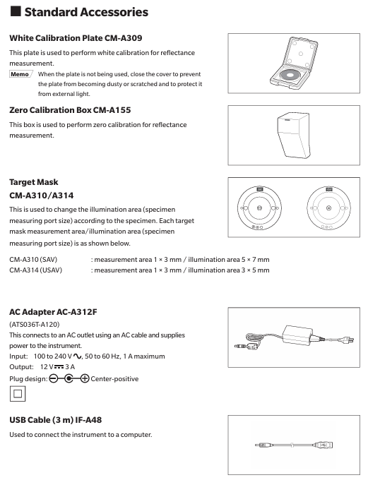
The white calibration board CM-A309 is used for reflectance measurement. When not in use, it needs to be covered to prevent dust accumulation, scratching, and exposure to external light
The zero calibration box CM-A155 is used for reflectance measurement. When using it for zero calibration, it should be installed correctly to avoid falling off due to external force, keep the interior clean, prevent scratching and fingerprint contamination, clean it according to regulations when it is dirty, and replace it if it is damaged and cannot be cleaned
When adjusting the illumination area (sample measurement port size) of the target mask CM-A310/A314 according to the sample, CM-A310 (SAV) has a measurement area of 1 × 3mm and an illumination area of 5 × 7mm. CM-A310 (SAV) must be used for zero calibration or white calibration of CM-A314 (USAV) with a measurement area of 1 × 3mm and an illumination area of 3 × 5mm. When installing, pay attention to the direction and avoid scratching the inner white coating surface. When not in use, place it in the accessory storage space
The AC adapter AC-A312F (ATS036T-A120) is connected to a power socket through an AC cable to supply power to the device. It has an input of 100-240V, 50-60Hz, maximum 1A, and an output of 12V 3A. The plug is the center positive pole, and this standard adapter must be used. When connecting, ensure that the plug is fully inserted to avoid short circuits and overloads, and do not wrap or cover it during use
USB cable IF-A48 (3m) is used to ensure correct direction and secure connection when connecting devices and computers. When plugging or unplugging, hold the plug and do not pull the cable to ensure sufficient cable length and avoid tension causing connection failure or cable breakage
(2) Optional attachments
Attachment Name Model/Relevant Information Purpose Acquisition Method/Instructions for Use
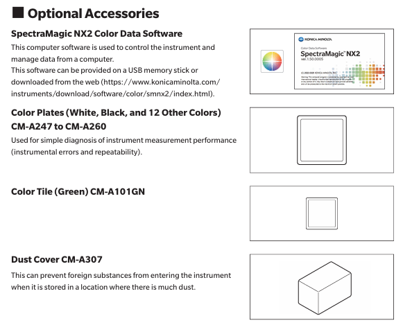
SpectraMagic NX2 Color Data Software - Used for controlling devices and managing data from a computer, which can be obtained through a USB flash drive or from the official website( https://www.konicaminolta.com/instruments/download/software/color/smnx2/index.html )To download and use, please refer to the software manual
Color palettes (white, black, and 12 other colors) CM-A247 to CM-A260 are used for measuring performance (instrument error and repeatability) of simple diagnostic equipment. When using them, follow the prescribed procedures to ensure that the measurement conditions meet the requirements
Green color chip CM-A101GN - used according to relevant operating specifications to assist in specific measurements or calibrations
When the dust cover CM-A307 device is stored in a dusty environment, it prevents foreign objects from entering the device. When covering the device, it ensures a snug fit and does not affect the normal heat dissipation of the device (used in non working conditions)
System diagram and component information
(1) System diagram
The CM-3700A-U Plus spectrophotometer can be connected to standard accessories (white calibration board CM-A309, zero calibration box CM-A155, target mask CM-A310/SAV, CM-A314/USAV, AC adapter AC-A312F, USB cable IF-A48) and optional accessories (SpectraMagic NX2 color data software, 14 color board CM-A247 to CM-A260, green color chip CM-A101GN, dust cover CM-A307). It can be connected to a computer through a USB cable to achieve computer control and data management of the equipment.
(2) Component Name and Function
Part Number, Part Name, Function
① Select a 5 × 7mm (SAV) or 3 × 5mm (USAV) illumination area for the target mask based on the sample to be measured, and install it on the device
② The sample rack is used to install reflectance measurement samples, white calibration plates, or zero calibration boxes
③ Environmental temperature and humidity meter measures the temperature and humidity of the environment
④ Fixture installation screw holes are used to install fixtures or other components to secure samples
⑤ When connecting the functional grounding terminal to the grounding wire, clamp the grounding wire between the screw and washer
⑥ USB connection terminal (Type B) connects devices and computers through the standard USB cable (IF-A48)
⑦ AC adapter input terminal connection provided
⑧ Attachment storage space stores attachments such as white calibration board, zero calibration box, target mask, etc
(3) Indicator light
Operation keys and power keys
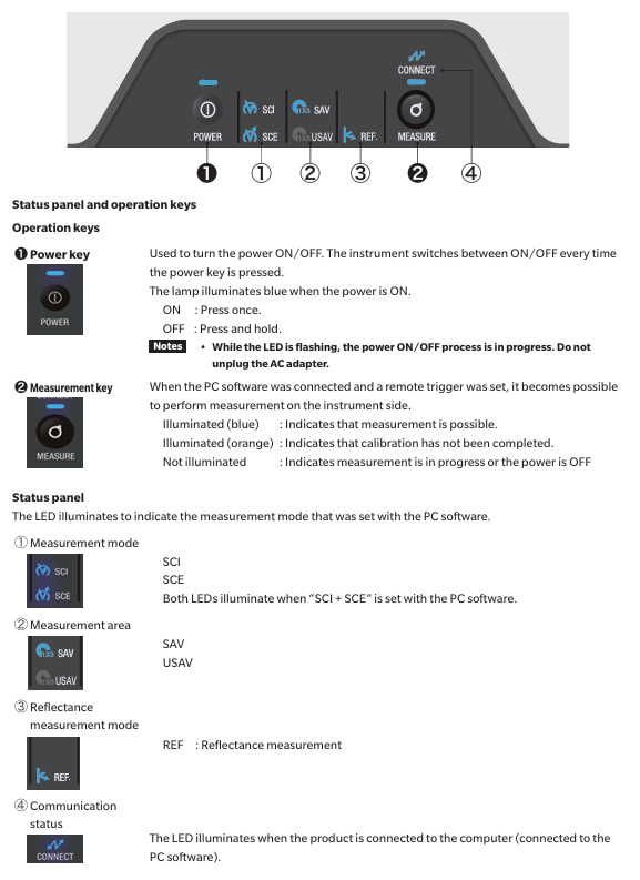
Power button (POWER): used to turn on/off the device power, press once to turn on, long press to turn off; When the power is turned on, the LED light above the key lights up in blue; When the LED light flashes, it indicates that the AC adapter cannot be unplugged during the power on/off process.
Measurement button: Blue light indicates that measurement can be performed; Orange light indicates incomplete calibration; Not lit indicates measurement or power off.
STATUS PANEL
Measurement mode indicator lights (SCI, SCE, REF, KREF.): The LED lights on indicate the measurement mode set through computer software. In the "SCI+SCE" mode, both the SCI and SCE lights are on simultaneously; REF represents reflectance measurement.
Measurement area indicator light (1X3): indicates the specifications of the measurement area.
Communication status indicator light (CONNECT): It lights up when the device is connected to the computer (connected to PC software).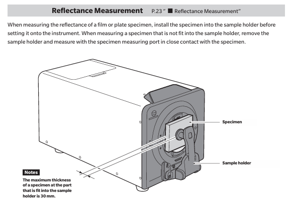
- YOKOGAWA
- Reliance
- ADVANCED
- SEW
- ProSoft
- WATLOW
- Kongsberg
- FANUC
- VSD
- DCS
- PLC
- man-machine
- Covid-19
- Energy and Gender
- Energy Access
- Renewable Integration
- Energy Subsidies
- Energy and Water
- Net zero emission
- Energy Security
- Critical Minerals
- A-B
- petroleum
- Mine scale
- Sewage treatment
- cement
- architecture
- Industrial information
- New energy
- Automobile market
- electricity
- Construction site
- HIMA
- ABB
- Rockwell
- Schneider Modicon
- Siemens
- xYCOM
- Yaskawa
- Woodward
- BOSCH Rexroth
- MOOG
- General Electric
- American NI
- Rolls-Royce
- CTI
- Honeywell
- EMERSON
- MAN
- GE
- TRICONEX
- Control Wave
- ALSTOM
- AMAT
- STUDER
- KONGSBERG
- MOTOROLA
- DANAHER MOTION
- Bentley
- Galil
- EATON
- MOLEX
- Triconex
- DEIF
- B&W
- ZYGO
- Aerotech
- DANFOSS
- KOLLMORGEN
- Beijer
- Endress+Hauser
- schneider
- Foxboro
- KB
- REXROTH
- YAMAHA
- Johnson
- Westinghouse
- WAGO
- TOSHIBA
- TEKTRONIX
- BENDER
- BMCM
- SMC
- HITACHI
- HIRSCHMANN
- XP POWER
- Baldor
- Meggitt
- SHINKAWA
- Other Brands
- UniOP
- KUKA
- IBA
- Beckhoff
- ADLINK
-
Beckhoff EP9224-0037 - 4-Channel Power Distribution Box EtherCAT
-
Beckhoff CX2900-0026 - Solid State Flash Memory Card 20GB CFast
-
Beckhoff BK7500 - SERCOS Interface Fieldbus Bus Coupler Terminal
-
Beckhoff Ep2328-0002 - 4-Channel Input 4-Channel Output EtherCAT Box IP67
-
Beckhoff CX1020-0111 - Controller Kit Combo Interface Modules
-
B&R X20AI2237 - X20 System Analog Input Interface Module
-
Beckhoff CP2221-0010 - Multi-Touch Built-In Panel PC Touchscreen
-
Beckhoff CX1500-M310 - Fieldbus Master Interface Module 24V
-
Beckhoff CX2100-0904 - Power Charging Module Smart UPS Extension
-
Beckhoff CP3918-0000 - Multi-Touch Control Panel 18.5-Inch Monitor
-
Beckhoff CP2915-0000 - 15-Inch Multi-Touch Built-In Control Panel
-
Beckhoff CP7037-1027 - HMI Industrial Control Panel Built-In PC
-
Beckhoff EL3152 - 2-Channel Analog Input Terminal 4-20mA EtherCAT
-
Beckhoff CP6607-0000-0020 - 5.7-Inch Built-In Panel PC HMI Touch
-
Beckhoff EJ1809-0000 - 16-Channel Digital Input Pluggable Signal Level Terminal
-
Beckhoff AM8563-0N10-0000 - Synchronous Servo Motor
-
Beckhoff AX2006-S60600-520 - Compact Servo Drive Inverter
-
Beckhoff AM8053-0K20-0000 - Servo Motor with Planetary Gearbox AG3210
-
Beckhoff AM8042-0FH1-0000 - Synchronous Servo Motor
-
Rexroth R911338600 - IndraControl V HMI Terminal Beckhoff PCI Card FC9002
-
Beckhoff AX5125-0000 - 3 Phase Industrial Servo Drive 1000Hz
-
Beckhoff EP2328-0002 - 4-Channel Digital Input 4-Channel Output EtherCAT Box
-
B&R 7CP476-02 - System 2005 RTD CPU Module 3IF681.86 Interface
-
Beckhoff AX8620-0000-0000 - Power Supply Module Axis Drive System
-
Beckhoff CX1010-0111 - PLC Module CPU Controller 24V
-
Beckhoff AM8043-0H10-0000 - Synchronous Servo Motor
-
Beckhoff C6240-1009 - Control Cabinet Industrial PC Mainframe
-
Beckhoff BX8000-0000 - Bus Terminal Controller HW 4.4 Standalone
-
Beckhoff CP7721-1089-0020 - 12.1-Inch Touch Screen HMI Panel PC
-
Beckhoff CP7132-0001 - Industrial Built-In Panel PC Screen
-
Beckhoff CP2912-0010 - Multi-Touch Built-In Control Panel Display
-
Beckhoff CP2915-0000 - 15-Inch Multi-Touch Built-In Control Panel
-
Beckhoff AM8532-1EN0-0000 - Synchronous Servo Motor
-
Beckhoff AX5203-0000 - 2-Channel Digital Compact Servo Drive
-
Beckhoff CX2020-0141 - Embedded PC Core CPU Module
-
Beckhoff CP6832-0002-0010 - Built-In Industrial Control Panel Display
-
Beckhoff CX5020-0112 - Embedded PC CPU Control Module
-
Beckhoff CX5140-0175 - 4GB Embedded PC CPU Unit 24V
-
Beckhoff EL3681-0030 - Digital Multimeter Calibration Terminal EtherCAT
-
Beckhoff CP7201-1000-0000 - Industrial PC Touch Screen HMI Monitor
-
Beckhoff CP7232-1001-0000 - Industrial Panel PC Touch Screen
-
Beckhoff C6930-1032-0040 - Control Cabinet Industrial PC System
-
Beckhoff AX5125-0000 - 3 Phase Industrial Servo Drive 1000Hz
-
Beckhoff CP3916-1424-0000 - Multi-Touch Built-In Control Panel
-
B&R 1900071142 - Lemoine Fieldbus Communication Interface Module
-
Beckhoff EL2872 - 16-Channel Ribbon Cable Digital Output Terminal
-
Beckhoff CX2030-0120 - Embedded PC CPU Base Module Controller
-
Beckhoff CP3919-0000 - 19-Inch Multi-Touch Control Panel Touchscreen
-
Beckhoff AX5101-0000-0202 - Servo Driver Compact Intelligent Drive 180V
-
Beckhoff CX5130-0135 - Embedded PC Controller Module
-
Beckhoff CP3719-1061-0010 - Multi-Touch Panel PC Outer Housing Enclosure
-
Beckhoff CP3919-1033-0000 - 19-Inch Touch Industrial Panel Keyboard
-
Beckhoff CX5020-0111 - Embedded PC PLC CPU Module
-
Beckhoff FC5102-0000 - 2-Channel CANopen PCI Control Board Card
-
Beckhoff CX9001-1101 - Embedded PC CPU Network I/O System Module
-
Beckhoff CX1100-0920 - Smart Position Sensor Interface Module
-
B&R 4P3040.01-490 - Operator Panel PLC Interface Communication Module
-
Beckhoff CP2612-0000 - Dual-Touch Built-In Panel PC HMI
-
Beckhoff CP7002-1043-0010 - Touchscreen Display HMI Panel Terminal
-
Beckhoff CX9020-0115 - Embedded PC Controller Module
-
Beckhoff CX5140-0155 - 4GB Embedded PC CPU Module Die Industry
-
B&R 7DI435.7 - System 2005 Universal Digital Input Output Module
-
Bihl+Wiedemann BWU1568 - AS-i Master to Profibus Gateway Module
-
Beckhoff C6920-0070 - Control Cabinet Industrial PC 8GB Win 10
-
B&R X20AI2322 - 2-Channel Temperature Analog Input Module
-
Beckhoff CP2912-0000 - 12-Inch Touchscreen Display Monitor Screen
-
Beckhoff CP6022-1001-0010 - 15-Inch Built-In Control Panel
-
Beckhoff AM8031-0D10-0000 - Synchronous Servo Motor
-
Beckhoff CX5010-0111 - Embedded PC Controller CPU Module
-
Beckhoff CP7232-1000-0000 - Industrial Panel PC Touch Display Screen
-
Beckhoff CP7802-0011-0000 - 15-Inch Industrial Touchscreen Control Panel
-
Beckhoff C6320 - Control Cabinet Industrial PC
-
Beckhoff CX1030-0012 - Basic CPU Module Windows CE 6.0
-
Beckhoff CP2919-0000 - Installation Multi-Touch Control Panel
-
Beckhoff CX1020-0000 - Controller Set Stack System Pack
-
B&R 3DO480.6 - System 2005 Digital Output Module
-
Beckhoff EL3101 - 1-Channel Analog Input Terminal Differential +/-10V
-
Beckhoff AX8108-0200-0000 - Axis Feed Module Servo Drive
-
Beckhoff CP7802-1241-0010 - 15-Inch Industrial Touchscreen Control Panel
-
Beckhoff FC2002-0000 - 2-Channel Lightbus Data Acquisition PCI Card
-
Beckhoff CX5120-0155 - 2GB Embedded PC Intel Atom Controller
-
Beckhoff Cx9020-0111 - 1GB Basic CPU Module Embedded PC
-
Beckhoff CP6901-0001-0000 - 12-Inch Economy Built-In Control Panel
-
Beckhoff CX9020-0111 - Embedded PC CPU Basic Module
-
Beckhoff CX5130-0100 - 4GB Embedded PC CPU Module
-
Beckhoff CP2715-0010 - Multi-Touch Built-In Panel PC
-
Beckhoff CX2033-0175 - Embedded PC CPU Module Core i7
-
Beckhoff CP7201-1000-0000 - 12-Inch Touchscreen Panel PC AMAT Green Box
-
Beckhoff EL4038 - 8-Channel Analog Output Terminal 0-10V EtherCAT
-
Beckhoff CP6802-0000-0000 - Built-In Control Panel HMI Screen
-
Beckhoff CP6500-1012-0060 - Control Cabinet PC Interface Unit
-
Beckhoff FC5202-0000 - 2-Channel DeviceNet Master PCI Interface Card
-
Beckhoff CP6606-0001-0020 - 7-Inch Economy Panel PC Touch
-
Beckhoff CP2921-0010 - Multi-Touch Integrated Control Panel Display
-
Beckhoff CP7802-0001-0010 - 15-Inch Touch Screen Control Panel HMI
-
Beckhoff C6920-0050 - Control Cabinet Industrial PC
-
Beckhoff BK9105 - EtherNet/IP Bus Coupler Network Interface
-
Beckhoff 31 Modules - Bus Terminal Slice I/O Lot Assortment
-
Beckhoff CX2020-0120 - Embedded PC Basic CPU Module 8GB CFast Card
-
Beckhoff CP7001-0000 - HMI Control Panel Touch Screen
-
B&R 7EX484.50-1 - System 2005 Controller Base Module Slots
-
Beckhoff EK1322 - 2-Port EtherCAT P Extension Feed-In Terminal
-
Beckhoff CP6606-0001-0020 - 7-Inch Single-Touch Economy Panel PC
-
Beckhoff CP6607-0001-0000 - Economy Installation Operator Panel PC 5.7-Inch
-
Beckhoff AX5103-0000-0200 - Digital Compact Servo Driver 3 Phase
-
Beckhoff CP7802-0001-0010 - 15-Inch Touch Screen Control Panel
-
Beckhoff AX8620 - Power Supply Module Axis System
-
Beckhoff CX2030-0121 - Embedded PC Controller Module
-
Beckhoff CP6606-0001-0020 - 7-Inch Economy Panel PC Touch Screen
-
Beckhoff CX2030-0121 - Embedded PC CPU Module Windows Standard 7
-
Beckhoff BX3100-0000 - PROFIBUS DP Bus Terminal Controller
-
Beckhoff CX1020-0000 - Controller Set with Power Supply Unit
-
Beckhoff EK1100 - EtherCAT Coupler Terminal Module Set
-
Beckhoff CP7002-1043-0010 - HMI Display Panel with Control Panel Bracket
-
Beckhoff AM8031-0D10-0000 - Synchronous Servo Motor
-
Beckhoff CX5130-0175 - Embedded PC 4GB RAM Controller
-
Beckhoff CX5130-0155 - Embedded PC Automation Controller
-
Beckhoff C6930-0010 - Control Cabinet Industrial PC Core Duo
-
Beckhoff CP3924-0000 - Multi-Touch Control Panel Display
-
Beckhoff AM8023-0F20-0000 - Synchronous Servo Motor
-
B&R KL3362 - Bus Terminal Thermocouple Input Module
-
Beckhoff AL2006-0000-0000 - Linear Servo Motor Three Phase
-
Beckhoff CX5140-0155 - Embedded PC CPU Controller Module
-
Beckhoff FC9002 - Ethernet PCI Network Interface Card
-
Beckhoff CP7203-0021-0040 - Built-In Panel PC 19-Inch Touch Screen
-
Beckhoff C6930-0020 - Control Cabinet Industrial PC HDD CF Card
-
Beckhoff CX2900-0033 - Memory Card CFast Storage
-
Beckhoff CP6201-0001-0020 - Built-In Panel PC Display

K-JIANG

Add: Jimei North Road, Jimei District, Xiamen, Fujian, China
Tell:+86-15305925923