
K-WANG


ABB Panel 800 Version 6 PP885 Hardware and Installation
ABB Panel 800 Version 6 PP885 Hardware and Installation
Product positioning: Panel 800 Version 6 PP885 is an operation panel designed for human-computer interaction scenarios, suitable for industrial control fields. It can be connected to automation equipment such as PLCs, servo systems, and drives to achieve functions such as text display and control, dynamic indication, time channel management, alarm processing, and formula management.
Safety precautions
(1) General safety requirements
Preparation: Installation personnel, equipment owners, and operators must read and understand this installation manual; Carefully read the safety precautions and check if there is any transportation damage to the delivered products. If there is any damage, immediately notify the supplier; Suppliers are not responsible for modified, altered, or modified equipment and are only allowed to use parts and accessories that meet the supplier's specifications.
Operation specifications: Before installing, using or repairing the operation panel, carefully read the installation and operation instructions; It is strictly prohibited for liquids, metal debris, or wiring debris to enter any opening of the operation panel to prevent fire or electric shock; Only qualified personnel are allowed to operate the control panel.
Storage and special case handling: The operation panel should be stored within the recommended temperature range. If the temperature is too low, it may cause the LCD display liquid to solidify, and if it is too high, it may cause isotopic phenomena; LCD display liquid contains highly irritating substances. If it comes into contact with the skin, immediately rinse with plenty of water. If it comes into contact with the eyes, open the eyes and rinse with plenty of water before seeking medical attention; The illustrations in the manual are only for illustration purposes. Due to the existence of multiple variables in the installation scenario, the supplier is not responsible for the actual use based on the illustrations; Suppliers do not guarantee that the operation panel is suitable for specific applications, nor are they responsible for product design, installation, or operation; It is recommended to perform at least one power on/off operation on the control panel before installing any components/cards or connecting external devices (such as serial devices).
(2) Disposal requirements under WEEE regulations
EU professional users: If you need to dispose of electrical and electronic equipment (EEE), you need to contact the distributor or supplier for further information.
Non EU country users: If you need to dispose of this product, you need to contact the local regulatory authority or distributor to understand the correct disposal method.
(3) UL and cUL installation requirements
Usage environment and power supply: The equipment is only suitable for Class 2 non hazardous locations; The combination of devices in the system must undergo inspection by the local regulatory authorities during installation; All devices must be powered by a Class 2 power supply, and disconnection is prohibited when powered on.
Expansion unit and battery: Only UL and cUL certified expansion units are allowed to be connected to ports labeled "EXPANSION", and there are currently no such evaluated or approved units for use; Before replacing the expansion unit, it is necessary to ensure that the power is turned off or that the area is non hazardous; The product contains batteries and can only be replaced in known non hazardous areas. BR 2032 batteries must be used, as using other types of batteries may pose a risk of fire or explosion; Improper handling of batteries may cause explosions. Charging, dismantling, or putting them into fire is prohibited.
Installation and wiring: can only be used on flat surfaces of Class 4 indoor enclosures; Only copper wires with a minimum temperature rating of 75 ° C are allowed to be used; The wiring connection of the power cord connector must comply with the cable and torque specifications (the torque corresponding to the wire size is 3.5 pounds per inch); These devices are Class 2 power supply programmable controllers (industrial PCs) suitable for industrial control equipment, intended for (front) panel installation (Class 1 and Class 4X, indoor use only); The protection level of the shell should be at least IP20, but it needs to reach IP54 when installed in the equipment.
(4) Safety requirements during installation
Installation environment: The operation panel is designed for fixed installation on a flat surface, and the installation environment must meet the conditions of no high explosion risk, no strong magnetic field, no direct sunlight, and no drastic temperature changes.
Installation operation specifications: Install the operation panel according to the attached installation instructions and perform grounding treatment; Only qualified personnel are allowed to install the operation panel; Separate the layout of high-voltage cables, signal cables, and power supply cables; Before connecting the power socket, it is necessary to confirm that the power voltage and polarity are correct; Peripheral devices need to be suitable for the application scenario and installation location.
Special area installation: In Zone 2 environment, the equipment needs to be installed in a casing with a protection level of not less than IP54 and not more than IP65 (in accordance with IEC/EN 600079-0 standard), and the IP level of the equipment is limited by the IP level of the installed casing; In the 22 zone environment, the equipment needs to be installed in an enclosure with a protection level of not less than IP64 and not more than IP65 (in accordance with IEC/EN 600079-0 standard), and the IP level of the equipment is also limited by the IP level of the enclosure.
(5) Safety requirements during use
Keep the operation panel clean; Emergency stop and other safety functions shall not be controlled through the operation panel; Do not use excessive force or sharp objects when operating the touch screen.
(6) Service and Maintenance Security Requirements
Only qualified personnel are allowed to carry out repairs; Follow the agreed warranty terms; Before performing any cleaning or maintenance operations, the power connection of the equipment must be disconnected; Clean the display screen and surrounding front cover with a soft cloth and mild cleaning agent; Improper battery replacement may result in explosion. Only use batteries recommended by the supplier. During the warranty period, batteries must be replaced by authorized ABB service centers.
(7) Dismantling and scrapping safety requirements
The operation panel or its components must be recycled and disposed of in accordance with local regulations; Components such as lithium batteries, electrolytic capacitors, and displays in the equipment contain substances that may be harmful to health and the environment.
(8) Air appears in the touch screen
The layered structure of the touch screen contains air, and in rare cases, bubbles may appear, which only affects the appearance and does not affect any function of the operation panel. This phenomenon may occur under specific environmental conditions such as temperature, humidity, and air pressure.
Installation related
(1) Space requirements
Installation plate thickness: The maximum installation plate thickness is 8mm.
Size requirements: When installing the operation panel, the space requirements in all directions (unit: mm) are as follows: 100mm (partial area), 286mm (partial area), 50mm (both sides), 53mm (partial area), 410mm (overall relevant dimensions). Please refer to the outline drawing in the manual for accurate installation dimensions, which are not drawn to scale.
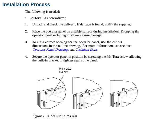
(2) Installation process
Preparation: Prepare Torx TX7 screwdriver; Unpack and inspect the delivered products. If any damage is found, notify the supplier; During installation, place the control panel on a stable surface to prevent it from falling and causing damage.
Cutting and fixing of openings: Cut suitable openings for the operation panel according to the opening size in the contour diagram (refer to the "Operation Panel Drawing" and "Technical Data" sections for detailed information); Use M4 Torx screws (specification M4 × 20.7, torque 0.4Nm) to secure the operation panel, ensuring that the built-in bracket is tightly attached to the panel.
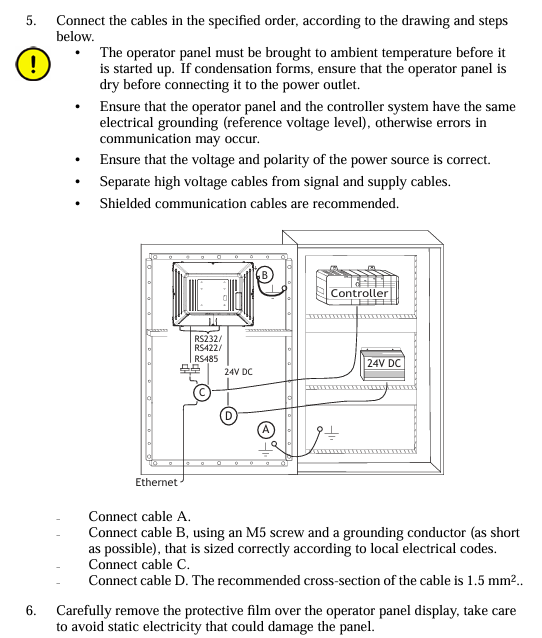
Cable connection: Connect the cables in the specified order according to the diagram and the following steps:
Before starting the operation panel, it is necessary to reach the ambient temperature. If condensation occurs, ensure that the operation panel is dry before connecting to the power outlet.
Ensure that the operation panel and controller system have the same electrical grounding (reference voltage level), otherwise communication errors may occur.
Confirm that the power supply voltage and polarity are correct; Separate high-voltage cables from signal cables and power supply cables; Suggest using shielded communication cables.
Connect cable A (24V DC); Connect cable B using M5 screws and grounding wire (as short as possible, with dimensions in accordance with local electrical regulations); Connect cable C (Ethernet); Connect cable D (RS232/RS422/RS485), with a recommended cable cross-section of 1.5mm ².
Removal of protective film: Carefully remove the protective film on the operation panel display screen, taking care to avoid static electricity damaging the panel.
(3) Connection with controller
For information on the cables used to connect the control panel to the controller, please refer to the help files of the relevant driver programs.
(4) Other connections and peripheral devices
Cables, peripheral devices, and accessories should be suitable for the application scenario and its environment. For detailed information or suggestions, please consult the supplier.
Technical data
Project parameters
Cover layer Autoflex EBA 180L (see "Chemical Resistance" section for details)
Shell material powder coated aluminum
Communication interface (1) 9-pin D-sub interface, supports RS232 RTS/CTS, chassis mounting female head, with standard locking screw (4-40 UNC)
Communication interface (2) 9-pin D-sub interface, supports RS232 RTS/CTS, chassis mounting female head, with standard locking screw (4-40 UNC)
Store 2GB SSD (NAND Flash) and support formats with a maximum storage capacity of 2GB
1GB of memory (DDR2)
One multi-color indicator light (on-chip integrated)
Lithium battery, model BR 2032 (or CR 2032)
Power consumption 24W
Power input 3.15A slow melting,+24V DC (18-32V DC)
Power compliance CE: The power supply must comply with the requirements of IEC 60950 and IEC 61558-2-4 standards; UL and cUL: The power supply must meet the requirements of Class 2 power supply
Display TFT-LCD with LED backlight, resolution 1280 × 800 pixels, 262k colors
Display performance: brightness of 450cd/m ², horizontal viewing angle of 160 °, vertical viewing angle of 140 °
Backlight lifespan of 50000 hours
Display screen size 331.2 × 207.0mm
Working temperature range -10 ° C to+50 ° C
Storage temperature range -20 ° C to+70 ° C
Working humidity range 5% -85% (no condensation)
CE certification complies with EMC Directive 2004/108/EC+A1:2011
Chemical resistance
(1) Metal casing
Powder coating has almost no or no resistance to the following chemicals at room temperature: concentrated acetic acid, toluene, 30% nitric acid, and 97 octane unleaded gasoline.
(2) Touch screen and covering material
Autoflex EBA 180L: Not tolerant to high-pressure steam above 100 ° C, nor to various chemical substances (specific substance and contact time requirements: some substances may have adverse effects after 10 minutes of contact, please refer to the detailed list in the manual).
Touch screen surface: After exposure to solvents such as toluene, there is no visible change on the touch screen surface of the operation panel (refer to the manual for a detailed solvent list).
Touch screen protective film: It is recommended to use Autoflex EBA 180L protective film (model RX885/893, can be ordered from ABB), and its chemical resistance is detailed in the "Autoflex EBA 180L" section; Like all polyester based films, Autoflex EBA 180L is not suitable for long-term exposure to direct sunlight; The layered structure of the touch screen contains air, and in rare cases, bubbles may appear, which only affect the appearance and not the function, and may occur under specific environmental conditions.
Operation panel drawing
(1) Connector
The drawings indicate the positions of connectors and related interfaces (such as COM1/2, LAN, USB, C LAN, COM3/4, etc.), but COM4 is not supported on TxB SoftControl and TxB SoftMotion that include EtherCAT functionality. For detailed interface layout and pin definitions, please refer to the illustrations in the manual.
(2) Communication port
Port function and connection: The communication port supports protocols such as RS232, RS422, RS485, etc. Some port pins are defined as follows (example): RS232 TxD, RS422 Rx+, GND, RS422 Tx -, RS485 Tx -/Rx -, etc. (detailed pin allocation reference manual diagram); COM4 is not supported on specific models.
Special connection requirements: If two communication ports need to be used on the same physical port, Y-shaped distribution cable TK860V001 (part number 3BSE069476R1) must be used.
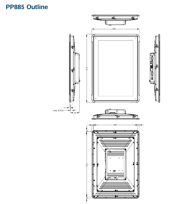
(3) PP885 contour
The contour diagram indicates the key dimensions of the operation panel (unit: mm), such as 286mm (partial length), maximum 8mm (related to installation plate thickness), 54mm (partial height), 268mm (partial length), 392mm (partial length), 410mm (overall length), etc. For detailed dimensions, please refer to the contour diagram in the manual.
- YOKOGAWA
- Reliance
- ADVANCED
- SEW
- ProSoft
- WATLOW
- Kongsberg
- FANUC
- VSD
- DCS
- PLC
- man-machine
- Covid-19
- Energy and Gender
- Energy Access
- Renewable Integration
- Energy Subsidies
- Energy and Water
- Net zero emission
- Energy Security
- Critical Minerals
- A-B
- petroleum
- Mine scale
- Sewage treatment
- cement
- architecture
- Industrial information
- New energy
- Automobile market
- electricity
- Construction site
- HIMA
- ABB
- Rockwell
- Schneider Modicon
- Siemens
- xYCOM
- Yaskawa
- Woodward
- BOSCH Rexroth
- MOOG
- General Electric
- American NI
- Rolls-Royce
- CTI
- Honeywell
- EMERSON
- MAN
- GE
- TRICONEX
- Control Wave
- ALSTOM
- AMAT
- STUDER
- KONGSBERG
- MOTOROLA
- DANAHER MOTION
- Bentley
- Galil
- EATON
- MOLEX
- Triconex
- DEIF
- B&W
- ZYGO
- Aerotech
- DANFOSS
- KOLLMORGEN
- Beijer
- Endress+Hauser
- schneider
- Foxboro
- KB
- REXROTH
- YAMAHA
- Johnson
- Westinghouse
- WAGO
- TOSHIBA
- TEKTRONIX
- BENDER
- BMCM
- SMC
- HITACHI
- HIRSCHMANN
- XP POWER
- Baldor
- Meggitt
- SHINKAWA
- Other Brands
- UniOP
- KUKA
- IBA
- Beckhoff
- ADLINK
-
Beckhoff EP9224-0037 - 4-Channel Power Distribution Box EtherCAT
-
Beckhoff CX2900-0026 - Solid State Flash Memory Card 20GB CFast
-
Beckhoff BK7500 - SERCOS Interface Fieldbus Bus Coupler Terminal
-
Beckhoff Ep2328-0002 - 4-Channel Input 4-Channel Output EtherCAT Box IP67
-
Beckhoff CX1020-0111 - Controller Kit Combo Interface Modules
-
B&R X20AI2237 - X20 System Analog Input Interface Module
-
Beckhoff CP2221-0010 - Multi-Touch Built-In Panel PC Touchscreen
-
Beckhoff CX1500-M310 - Fieldbus Master Interface Module 24V
-
Beckhoff CX2100-0904 - Power Charging Module Smart UPS Extension
-
Beckhoff CP3918-0000 - Multi-Touch Control Panel 18.5-Inch Monitor
-
Beckhoff CP2915-0000 - 15-Inch Multi-Touch Built-In Control Panel
-
Beckhoff CP7037-1027 - HMI Industrial Control Panel Built-In PC
-
Beckhoff EL3152 - 2-Channel Analog Input Terminal 4-20mA EtherCAT
-
Beckhoff CP6607-0000-0020 - 5.7-Inch Built-In Panel PC HMI Touch
-
Beckhoff EJ1809-0000 - 16-Channel Digital Input Pluggable Signal Level Terminal
-
Beckhoff AM8563-0N10-0000 - Synchronous Servo Motor
-
Beckhoff AX2006-S60600-520 - Compact Servo Drive Inverter
-
Beckhoff AM8053-0K20-0000 - Servo Motor with Planetary Gearbox AG3210
-
Beckhoff AM8042-0FH1-0000 - Synchronous Servo Motor
-
Rexroth R911338600 - IndraControl V HMI Terminal Beckhoff PCI Card FC9002
-
Beckhoff AX5125-0000 - 3 Phase Industrial Servo Drive 1000Hz
-
Beckhoff EP2328-0002 - 4-Channel Digital Input 4-Channel Output EtherCAT Box
-
B&R 7CP476-02 - System 2005 RTD CPU Module 3IF681.86 Interface
-
Beckhoff AX8620-0000-0000 - Power Supply Module Axis Drive System
-
Beckhoff CX1010-0111 - PLC Module CPU Controller 24V
-
Beckhoff AM8043-0H10-0000 - Synchronous Servo Motor
-
Beckhoff C6240-1009 - Control Cabinet Industrial PC Mainframe
-
Beckhoff BX8000-0000 - Bus Terminal Controller HW 4.4 Standalone
-
Beckhoff CP7721-1089-0020 - 12.1-Inch Touch Screen HMI Panel PC
-
Beckhoff CP7132-0001 - Industrial Built-In Panel PC Screen
-
Beckhoff CP2912-0010 - Multi-Touch Built-In Control Panel Display
-
Beckhoff CP2915-0000 - 15-Inch Multi-Touch Built-In Control Panel
-
Beckhoff AM8532-1EN0-0000 - Synchronous Servo Motor
-
Beckhoff AX5203-0000 - 2-Channel Digital Compact Servo Drive
-
Beckhoff CX2020-0141 - Embedded PC Core CPU Module
-
Beckhoff CP6832-0002-0010 - Built-In Industrial Control Panel Display
-
Beckhoff CX5020-0112 - Embedded PC CPU Control Module
-
Beckhoff CX5140-0175 - 4GB Embedded PC CPU Unit 24V
-
Beckhoff EL3681-0030 - Digital Multimeter Calibration Terminal EtherCAT
-
Beckhoff CP7201-1000-0000 - Industrial PC Touch Screen HMI Monitor
-
Beckhoff CP7232-1001-0000 - Industrial Panel PC Touch Screen
-
Beckhoff C6930-1032-0040 - Control Cabinet Industrial PC System
-
Beckhoff AX5125-0000 - 3 Phase Industrial Servo Drive 1000Hz
-
Beckhoff CP3916-1424-0000 - Multi-Touch Built-In Control Panel
-
B&R 1900071142 - Lemoine Fieldbus Communication Interface Module
-
Beckhoff EL2872 - 16-Channel Ribbon Cable Digital Output Terminal
-
Beckhoff CX2030-0120 - Embedded PC CPU Base Module Controller
-
Beckhoff CP3919-0000 - 19-Inch Multi-Touch Control Panel Touchscreen
-
Beckhoff AX5101-0000-0202 - Servo Driver Compact Intelligent Drive 180V
-
Beckhoff CX5130-0135 - Embedded PC Controller Module
-
Beckhoff CP3719-1061-0010 - Multi-Touch Panel PC Outer Housing Enclosure
-
Beckhoff CP3919-1033-0000 - 19-Inch Touch Industrial Panel Keyboard
-
Beckhoff CX5020-0111 - Embedded PC PLC CPU Module
-
Beckhoff FC5102-0000 - 2-Channel CANopen PCI Control Board Card
-
Beckhoff CX9001-1101 - Embedded PC CPU Network I/O System Module
-
Beckhoff CX1100-0920 - Smart Position Sensor Interface Module
-
B&R 4P3040.01-490 - Operator Panel PLC Interface Communication Module
-
Beckhoff CP2612-0000 - Dual-Touch Built-In Panel PC HMI
-
Beckhoff CP7002-1043-0010 - Touchscreen Display HMI Panel Terminal
-
Beckhoff CX9020-0115 - Embedded PC Controller Module
-
Beckhoff CX5140-0155 - 4GB Embedded PC CPU Module Die Industry
-
B&R 7DI435.7 - System 2005 Universal Digital Input Output Module
-
Bihl+Wiedemann BWU1568 - AS-i Master to Profibus Gateway Module
-
Beckhoff C6920-0070 - Control Cabinet Industrial PC 8GB Win 10
-
B&R X20AI2322 - 2-Channel Temperature Analog Input Module
-
Beckhoff CP2912-0000 - 12-Inch Touchscreen Display Monitor Screen
-
Beckhoff CP6022-1001-0010 - 15-Inch Built-In Control Panel
-
Beckhoff AM8031-0D10-0000 - Synchronous Servo Motor
-
Beckhoff CX5010-0111 - Embedded PC Controller CPU Module
-
Beckhoff CP7232-1000-0000 - Industrial Panel PC Touch Display Screen
-
Beckhoff CP7802-0011-0000 - 15-Inch Industrial Touchscreen Control Panel
-
Beckhoff C6320 - Control Cabinet Industrial PC
-
Beckhoff CX1030-0012 - Basic CPU Module Windows CE 6.0
-
Beckhoff CP2919-0000 - Installation Multi-Touch Control Panel
-
Beckhoff CX1020-0000 - Controller Set Stack System Pack
-
B&R 3DO480.6 - System 2005 Digital Output Module
-
Beckhoff EL3101 - 1-Channel Analog Input Terminal Differential +/-10V
-
Beckhoff AX8108-0200-0000 - Axis Feed Module Servo Drive
-
Beckhoff CP7802-1241-0010 - 15-Inch Industrial Touchscreen Control Panel
-
Beckhoff FC2002-0000 - 2-Channel Lightbus Data Acquisition PCI Card
-
Beckhoff CX5120-0155 - 2GB Embedded PC Intel Atom Controller
-
Beckhoff Cx9020-0111 - 1GB Basic CPU Module Embedded PC
-
Beckhoff CP6901-0001-0000 - 12-Inch Economy Built-In Control Panel
-
Beckhoff CX9020-0111 - Embedded PC CPU Basic Module
-
Beckhoff CX5130-0100 - 4GB Embedded PC CPU Module
-
Beckhoff CP2715-0010 - Multi-Touch Built-In Panel PC
-
Beckhoff CX2033-0175 - Embedded PC CPU Module Core i7
-
Beckhoff CP7201-1000-0000 - 12-Inch Touchscreen Panel PC AMAT Green Box
-
Beckhoff EL4038 - 8-Channel Analog Output Terminal 0-10V EtherCAT
-
Beckhoff CP6802-0000-0000 - Built-In Control Panel HMI Screen
-
Beckhoff CP6500-1012-0060 - Control Cabinet PC Interface Unit
-
Beckhoff FC5202-0000 - 2-Channel DeviceNet Master PCI Interface Card
-
Beckhoff CP6606-0001-0020 - 7-Inch Economy Panel PC Touch
-
Beckhoff CP2921-0010 - Multi-Touch Integrated Control Panel Display
-
Beckhoff CP7802-0001-0010 - 15-Inch Touch Screen Control Panel HMI
-
Beckhoff C6920-0050 - Control Cabinet Industrial PC
-
Beckhoff BK9105 - EtherNet/IP Bus Coupler Network Interface
-
Beckhoff 31 Modules - Bus Terminal Slice I/O Lot Assortment
-
Beckhoff CX2020-0120 - Embedded PC Basic CPU Module 8GB CFast Card
-
Beckhoff CP7001-0000 - HMI Control Panel Touch Screen
-
B&R 7EX484.50-1 - System 2005 Controller Base Module Slots
-
Beckhoff EK1322 - 2-Port EtherCAT P Extension Feed-In Terminal
-
Beckhoff CP6606-0001-0020 - 7-Inch Single-Touch Economy Panel PC
-
Beckhoff CP6607-0001-0000 - Economy Installation Operator Panel PC 5.7-Inch
-
Beckhoff AX5103-0000-0200 - Digital Compact Servo Driver 3 Phase
-
Beckhoff CP7802-0001-0010 - 15-Inch Touch Screen Control Panel
-
Beckhoff AX8620 - Power Supply Module Axis System
-
Beckhoff CX2030-0121 - Embedded PC Controller Module
-
Beckhoff CP6606-0001-0020 - 7-Inch Economy Panel PC Touch Screen
-
Beckhoff CX2030-0121 - Embedded PC CPU Module Windows Standard 7
-
Beckhoff BX3100-0000 - PROFIBUS DP Bus Terminal Controller
-
Beckhoff CX1020-0000 - Controller Set with Power Supply Unit
-
Beckhoff EK1100 - EtherCAT Coupler Terminal Module Set
-
Beckhoff CP7002-1043-0010 - HMI Display Panel with Control Panel Bracket
-
Beckhoff AM8031-0D10-0000 - Synchronous Servo Motor
-
Beckhoff CX5130-0175 - Embedded PC 4GB RAM Controller
-
Beckhoff CX5130-0155 - Embedded PC Automation Controller
-
Beckhoff C6930-0010 - Control Cabinet Industrial PC Core Duo
-
Beckhoff CP3924-0000 - Multi-Touch Control Panel Display
-
Beckhoff AM8023-0F20-0000 - Synchronous Servo Motor
-
B&R KL3362 - Bus Terminal Thermocouple Input Module
-
Beckhoff AL2006-0000-0000 - Linear Servo Motor Three Phase
-
Beckhoff CX5140-0155 - Embedded PC CPU Controller Module
-
Beckhoff FC9002 - Ethernet PCI Network Interface Card
-
Beckhoff CP7203-0021-0040 - Built-In Panel PC 19-Inch Touch Screen
-
Beckhoff C6930-0020 - Control Cabinet Industrial PC HDD CF Card
-
Beckhoff CX2900-0033 - Memory Card CFast Storage
-
Beckhoff CP6201-0001-0020 - Built-In Panel PC Display

K-JIANG

Add: Jimei North Road, Jimei District, Xiamen, Fujian, China
Tell:+86-15305925923