
K-WANG
+086-15305925923
Service expert in industrial control field!


Product
Article
NameDescriptionContent
Adequate Inventory, Timely Service
pursuit of excellence


Ship control system
Equipment control system
Power monitoring system
Current position:
新闻动态
newS
Brand
ABB COM610 Communication Gateway
ABB COM610 Communication Gateway
ABB COM610 Communication Gateway
• Protocol conversion gateway for substation
automation:
- Process communication: LON-LAG,
SPA, IEC 60870-5-103, IEC 61850-8-1,
Modbus serial, Modbus TCP, DNP3
serial, DNP3 TCP
- Remote communication: IEC 60870-5-
101, IEC 60870-5-104, DNP 3.0 Serial,
DNP 3.0 LAN/WAN, SPA Router, External OPC Client (DA, AE)
• True IEC 61850 communication gateway:
- IEC 61850-6 - Substation Configuration
Language (SCL)
- IEC 61850 -7 - Communication modeling and cross-referencing between protocols
- IEC 61850-8-1 - Mapping for MMSTCP/IP – Ethernet
• Configuration:
- Efficient and intuitive configuration tool
- Cross-referencing between protocols
based on the IEC61850-7 models
- Drag-and-drop protocol mapping to map
complete structures from the source
data
- Efficient handling of large amounts of
data in list views
- Tooltips
- Remote configuration and administration
• Communication redundancy (requires
optional LAN card)
- IEC 62439/PRP (parallel redundance
protocol)
- SFT (switch fault tolerance)
• Extensive support for commissioning and
diagnostics:
- Online diagnostics for different components
- Communication diagnostic counters on
the network and device level
- Real time process data monitoring and
controlling for all devices and protocols
- Source data monitoring and simulation:
- Testing the data mapping for NCCs
also with no online IEDs
- Simulating complete IEDs
- Communication diagnostic event list for
all devices and protocols:
- Resembles a high level protocol analyser
- Monitors the reported values and
events and the received control commands
• Web server for diagnostic information:
- Requires only a web browser and a
TCP/IP connection - no pre-installations
• MNS iS connectivity
- Connectivity to ABB’s Low Voltage
Motor Control Center MNS iS with an
OPC server in COM600. COM600
receives data from the MNS iS devies
and provides HMI and gateway functionality
• Security:
- User authentication
- Individual user accounts
- Password authentication
- Role-based access control
- Host-based firewalls
- Communication encryption HTTPS
Application COM610 3.2 is a communication gateway
that maps signals between the protection and
control IEDs in industrial or utility substations and higher-level systems such as Network Control Centres (NCC) or Distributed
Control Systems (DCS).
COM610 3.2 sends information for monitoring and controlling the process to NCC and
DCS and receives process control commands
from them. COM610 3.2 also handles system
co-ordination tasks, such as the dynamic
assignment of control command authorisation
and communication supervision. COM610
3.2 is typically connected to a NCC via a telecontrol protocol, or to a DCS using the OPC
Server/Client technology. You can use different protocols to connect process devices to
COM610 3.2. COM610 3.2 is a true IEC
61850 gateway and supports all applicable
IEC 61850 parts.
Fig. 1 displays an overview of a typical utility
system with the COM610 Gateway.
Fig. 2 displays an industrial system overview.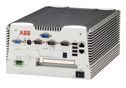
The LON-LAG protocol uses a specific board
to connect the fibres, both plastic and glass.
COM610 3.2 can have one board, that is, one
LON line.
It is possible to extend COM610 3.2 by
increasing the number of Ethernet interfaces
thus increasing the number of Ethernets lines.
Connectivity Packages
To make the configuration of COM610 3.2
more efficient, Connectivity Packages are
available for ABB’s protection and control
IEDs. A Connectivity Package includes
descriptions of data and signals available in
the IED, and the descriptions are used to
automatically configure the master communication in the COM610 3.2 gateway. Connectivity Packages for some IEDs are already
available, and more will be released in due
couse. At present the following Connectivity
Packages are available:
- REF 541/3/5, REM 543/5, RET 541/3/5
- REF 542plus
- REX 521
- RE_610
- SPACOM (Conn Pack v. 2.0 supports
SPAJ 140, SPAJ 141, SPAJ 142, SPAJ
144, SPAD 346, SACO 16D1, SACO
16D2, SACO 64D4)
COM610 gateway unit’s configurability and
functionality depends on the type of communication protocol used for communication
between the COM610 and the IEDs. For
more details, please refer to the document
“Protocols versus Functions for IEDs”,
1MRS756223.
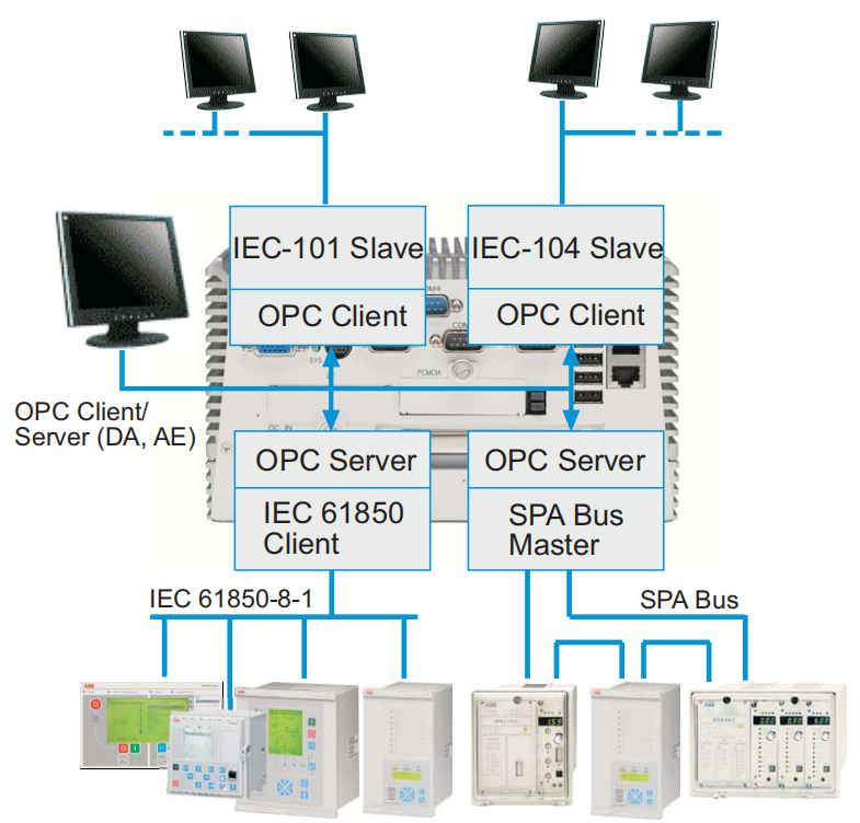
The COM610 gateway consists of the OPC
Data Access (DA, AE) server and client com ponents. The OPC Servers provide the mas ter/client protocol stacks access to the data in
the devices connected with the protocol. The
slave/server protocol stacks use the OPC Cli ents to provide the external systems access to
the data available in the OPC Servers.
Fig. 3 Example of COM610 Gateway components
Available protocols
The table below displays the protocols sup ported by COM610 Gateway. New protocols
will be available according to the market
demands.
The process communication uses the master
protocols and the upper level communication
uses the slave protocols. For more detailed
information on the protocols, refer to the
User’s guides listed in References.
Master Slave
LON - LAG IEC 60870-5-101
SPA IEC 60870-5-104
IEC 60870-5-103 DNP 3.0 Serial
IEC 61850-8-1 DNP 3.0 LAN/WAN
Modbus serial SPA Router
Modbus TCP External OPC Client
DNP3 serial
DNP3 TCP
System requirements for the
Communication
Engineering Tool
Hardware requirements
The Communication Engineering Tool runs
on Microsoft® Windows® XP. A PC capable
of running this program is usually sufficient
also for running the Communication Engineering Tool.
Microsoft® .NET Framework 2.0 is required
for running the Communication Engineering
Tool.
It is automatically installed during the installation of the Communication Engineering
Tool if it is not already available on the PC.
• Free hard disk space required: minimum
500 MB, recommended 1 GB.
Technical data Hardware Design
• Ruggedised mechanics
- No moving parts - no fans, no hard
disks
• System
- Intel® Pentium® M 1.6 GHz
- 1 GB SDRAM System Memory
- 2 GB Industrial SSD Compact Flash
memory
• Power supply units:
- 76-240 V dc
• Interfaces
- 3 RS 232 serial ports
- 1 RS 232/485 serial port
- 2 10/100Base-TX RJ-45 connector
- 4 USB 2.0 ports
- Optional PCI extensions:
- 1 LON interface
(Operating temperature 0°C - +70°C)
- 8 RS232/485 serial interfaces (Operating temperature 0°C - +55°C)
- 2 10/100/1000Base-TX RJ-45 connectors (Operating temperature 0°C -
+60°C)
• Mechanics and Environment:
- Operation -25°C to +70°C
- Storage -40°C to +70°C
- Dimensions (without fastening brackets): 214 mm (W) x 122.5 mm (H) x
313 mm (D)
- Net weight: 6.8 kg
- Degree of protection: IP 4x
- Operating humidity: 5-95% at +40°C,
non-condensing
- EMC CE/FCC class B
- Anti-vibration and anti-shock tests
Table 1: Inspection of mechanical structure
Description Reference
Markings and mechanical structure IEC 60255-5, -6
Degree of protection by enclosure IEC 60529
Clearance and creepage distances IEC 60255-5
Table 2: Power supply module tests
Description Reference
Auxiliary voltage IEC 60255-6
Aux. voltage interruptions IEC 60255-11
Ripple in auxiliary dc voltage IEC 60255-11
12%, f = 2 x fn
Power consumption CE EN 61010
Table 3: Insulation tests
Test Reference Requirement
Dielectric test IEC 60255-5 2 kV, 50 Hz for 1 minute
Impulse voltage test IEC 60255-5 5 kV, 1.2/50 μs, 0.5 J
Insulation resistance IEC 60255-5 >100 MΩ, 500 Vdc
Protective bonding impedance IEC 60255-27 <0.1 Ω.
Table 4: Electromagnetic compatibility tests
Test Reference Requirement
1 MHz burst test IEC 60255-22-1 - differential mode: 1 kV
- common mode: 2.5 kV
ESD IEC 61000-4-2
IEC 60255-22-2
- contact discharge: 6 kV
- air discharge: 8 kV
RF field immunity IEC 61000-4-6 3 V/m (80% amp.mod.)
f = 80 MHz...1000 MHz
30 V/m (pulse mod.)
f = 900 MHz
Fast transient IEC 61000-4-4
IEC 60255-22-4
Power supply:
common mode 4 kV:
- current inputs CT1…CT5
- voltage inputs VT1…VT4
- sensor inputs (coupling clamp)
Power outputs:
common mode 2 kV:
- signal outputs
- digital inputs
- IRF relay
Surge IEC 61000-4-5
IEC 60255-22-5
4 kV line to earth /2 kV line to line
- power supply
- current inputs CT1…CT5
- voltage inputs VT1…VT4
- power outputs
2 kV line to earth /1 kV line to line
- signal outputs
- digital inputs
- IRF relay
Conducted radio frequency disturbance
IEC 61000-4-6
IEC 60255-22-6
10 V (80% amp.mod.)
f = 150 kHz...80 MHz
- YOKOGAWA
- Reliance
- ADVANCED
- SEW
- ProSoft
- WATLOW
- Kongsberg
- FANUC
- VSD
- DCS
- PLC
- man-machine
- Covid-19
- Energy and Gender
- Energy Access
- Renewable Integration
- Energy Subsidies
- Energy and Water
- Net zero emission
- Energy Security
- Critical Minerals
- A-B
- petroleum
- Mine scale
- Sewage treatment
- cement
- architecture
- Industrial information
- New energy
- Automobile market
- electricity
- Construction site
- HIMA
- ABB
- Rockwell
- Schneider Modicon
- Siemens
- xYCOM
- Yaskawa
- Woodward
- BOSCH Rexroth
- MOOG
- General Electric
- American NI
- Rolls-Royce
- CTI
- Honeywell
- EMERSON
- MAN
- GE
- TRICONEX
- Control Wave
- ALSTOM
- AMAT
- STUDER
- KONGSBERG
- MOTOROLA
- DANAHER MOTION
- Bentley
- Galil
- EATON
- MOLEX
- Triconex
- DEIF
- B&W
- ZYGO
- Aerotech
- DANFOSS
- KOLLMORGEN
- Beijer
- Endress+Hauser
- schneider
- Foxboro
- KB
- REXROTH
- YAMAHA
- Johnson
- Westinghouse
- WAGO
- TOSHIBA
- TEKTRONIX
- BENDER
- BMCM
- SMC
- HITACHI
- HIRSCHMANN
- XP POWER
- Baldor
- Meggitt
- SHINKAWA
- Other Brands
- UniOP
- KUKA
- IBA
- Beckhoff
- ADLINK
51
-
Beckhoff KL3162 - PLC Module KL 3162
-
Beckhoff EL3255 - PLC module
-
Beckhoff AX5201-0000 - servo driver
-
Beckhoff CX5130-0125 - Embedded PC Intel Atom 1.75GHz processor, 4GB DDR3 RAM
-
Beckhoff CU1521 - industrial switch
-
Beckhoff C6920-1057-0030 - #NAME?
-
B&R 7CP476.60-1 - 1 module 1
-
Beckhoff KL2552 - PLC module
-
Beckhoff CP6223-0002-0060 - #NAME?
-
Unknown BK7350-1060 - EtherCAT bus coupler
-
Beckhoff CX2040-0155 - Automation Basic CPU module, Windows 10 IoT Enterprise
-
Beckhoff CX5230-0175 - 000029724 Embedded PC Industrial PC On Rail
-
Beckhoff EL4134 - PLC Modules
-
Beckhoff EK1100 - automation coupling module EtherCat coupler coupling modules
-
Beckhoff EL6201 - Programmable Controller Module
-
Beckhoff CX2033-0175 - 000107116 embedded PC
-
Beckhoff AM3021-0C40-0000 - #NAME?
-
Beckhoff CX1020-0021 - CPU Module
-
Beckhoff CX2030 - PLC CPU Module
-
Beckhoff CX5130-0120 - PLC Modules
-
Beckhoff CX5230-0175 - 000029724 Embedded Controller Auf Schiene Industrial Pc
-
Beckhoff CX5130-0175 - PC CPU Module HW 4.4 Intel Atom Industrial CX2900 0038 40GB
-
Beckhoff AX5125-0000-0200 - #NAME?
-
Beckhoff KL3011 - One PLC Module
-
Beckhoff CX2020-0120 - 4 GB Basic CPU Module
-
Beckhoff CX1100-0920 - PLC CPU Module Module
-
AB 20F11NC3P5JA0NNNNN - Industrial Automation Part
-
Beckhoff AX5206-0000-0200 - #NAME?
-
Beckhoff CP6700-0001-0050 - , -
-
Beckhoff BECKHOFF-FOR-CX2000-4GB-CFAST-CARD-SLC-FLASH - - - -
-
B&R X67BC6321.L12 - X67 SYSTEM
-
Beckhoff CX9000-0001 - Controller module
-
Beckhoff AX5206-0000-0200 - #NAME?
-
Beckhoff CP2919-0000 - Multitouch Built In Control Panel 24VDC 19"
-
Beckhoff CP6032-0000-0010 - - 15" OPERATOR CONTROL PANEL
-
Beckhoff KL2791 - PLC module
-
Beckhoff CP7902-0001-0000 - - Touch Panel Power Supply 24VDC
-
Beckhoff CP6702-0001 - Open Interface Panels
-
Beckhoff CU8800-0010 - Communication / Interface Module Module
-
Beckhoff C6920-0010 - Driver
-
Beckhoff EL6614 - EtherCAT / Bus Terminal
-
Beckhoff AX5203-0000-0200 - #NAME?
-
Beckhoff EK1322 - 2 port EtherCATP junction Rev 0017
-
Beckhoff EP2349-0021-16 - EtherCAT Box - 16 Channel Module
-
Beckhoff CP6801-0021-0010 - Touch Panel - 12" 14 1 1020
-
Beckhoff CX1020-0112 - - N00 N010 CX1100 0004 PLC CONTROLLER R1S13.7
-
Beckhoff EL2784 - EtherCAT / Bus Terminal Module
-
Beckhoff CX2020-0155 - PLC CPU Module Module
-
Beckhoff EK1914 - PLC EK 1914 Module
-
Beckhoff Cx5130-0122 - PLC CPU Module
-
Beckhoff CX5010-0112 - CPU module
-
Beckhoff CP7811-0001 - - 0 0
-
Beckhoff EL3162 - controller module
-
Beckhoff CU2508-0000 - 8 Port Port Multiplier PLC Processor
-
Beckhoff CX5010-1112 - Mod CPU Module K Bus Windows Runtime TwinCAT 2 NC
-
Beckhoff BECKHOFF-CX2100-0914-CX21000914 - Industrial Automation Part
-
Beckhoff CX1500-M310 - PLC Module
-
B&R 7CP476.60-1 - 1 module 1
-
Beckhoff EL5042 - EtherCAT / Bus Terminal
-
B&R AT6402 - X20 PLC MODULE X20 ORIGINAL
-
Beckhoff CP7802-1327-0010 - #NAME?
-
Beckhoff CX1100-0002 - Power Module
-
Beckhoff CX2040-0155 - PLC CPU Module
-
Beckhoff EP1809-0021 - PLC Modules
-
Beckhoff CX2040 - 0142 Communication Module
-
Beckhoff CX2900-0033 - PLC CPU Module
-
Beckhoff CX2500-0030 - Interface Module
-
Beckhoff EK1100 - Module Ethernet Kommunikaton Modul
-
Beckhoff KL4428 - Bus Terminal 8 Channel Analog Output
-
Beckhoff CX5130-0122 - embedded PC CPU module 4 GB industrial PC CPU module HW 3.5
-
Beckhoff CX9020-0111-1002 - PLC CPU Module
-
Beckhoff CP6929-0001-0000 - Touchscreen Panel 6.5" ELO Model -
-
Beckhoff EP4174-0002 - Module HTP0
-
Beckhoff CP6092-0011-0000 - - Touch Screen 15" Panel
-
B&R 5WCC00000440K0-001 - PANEL PC 2100 SYSTEM UNIT AUTOMATION PANEL
-
Beckhoff CX2100-0014 - Original
-
Beckhoff CX5120-0115 - 3243
-
Beckhoff CP3919-1039-0011 - Multi Touch Control Panel - 19" G190ETN01.2
-
Beckhoff CX9001-0101 - PLC Module QW
-
Beckhoff BECKHOFF-CX5120-121 - Industrial Automation Part
-
Beckhoff BECKHOFF-BX8000-0000 - Industrial Automation Part
-
Beckhoff AX511200000200 - AX5112 0000 0200 Servo Driver
-
Beckhoff EL2564 - EtherCAT Terminal, 4 channel LED output, 5 8VDC, 4A, RGBW
-
Beckhoff KL4494 - EtherCAT / Bus Terminal
-
B&R 5e9000.17 - Control Panel
-
Beckhoff BX8000 - PLC Module
-
Beckhoff AS1060-0110 - , Stepper Motor Precision .........
-
B&R 0702-10B - 6PPT50. Touch Panel
-
Beckhoff C6930-0050 - Schaltschrank Industrie Pc Core i7 4700 CPU+FC9062 Module
-
Beckhoff KL2702 - PLC Controller Module
-
Beckhoff EL4038 - Communication Module
-
Beckhoff EK1110-0008 - EtherCAT / Bus Terminal Module
-
Beckhoff CX5020-0111 - PLC CPU Module
-
Beckhoff CP7232-0001-0050 - #NAME?
-
Beckhoff FC3101-0000 - communication module
-
Beckhoff EL6930 - EtherCAT Klemme
-
Beckhoff EL6631 - EtherCAT / Bus Terminal
-
Beckhoff EK1100 - ,EL2202,EL1904,EL1809,EL9189,EL9188,EL2809,EL3122,EL3102,EL4102
-
Beckhoff EL6695 - EtherCAT / Bus Terminal
-
Beckhoff CX1500-M510 - CX1020 N000 CX1020 0011 CX1100 0002 Controller Set
-
Beckhoff AM8052-1F20-0000 - - motor -
-
Beckhoff C6925-1004 - Industrial PC
-
Beckhoff 7132-0001 - CPPC
-
Beckhoff CP6001-0011-0010 - - Control Panel 12 inch TFT Display, 001...
-
Beckhoff CX2020-0120 - 4GB CPU ,CX2100 0904 3x EL6900, EL1904 16 GB Memory
-
Beckhoff C6920-0030 - Controller
-
B&R 3DM486.6 - DIGITAL MIXED MODULE DM486
-
Beckhoff KL3361 - PLC Module KL 3361
-
Beckhoff C9900-H391 - operating system
-
Unknown CKS-10T - Industrial Automation Part
-
Beckhoff AX5206-0000 - server Driver
-
Beckhoff CP6800-0001-000 - #NAME?
-
Beckhoff CX1100-0920 - Module 24VDC Controller Module
-
Schneider 140CRP31200 - IPC PLC Module In Box
-
Beckhoff C6930-1001 - Industrial PC
-
Beckhoff FC9002 - FC 9002 Ethernet PCI Network Card
-
Beckhoff EL6070-1296 - license key terminal EtherCAT
-
Beckhoff CP7721-1036-0010 - Display Control Panel
-
Beckhoff FC3101 - 2022 Module
-
Beckhoff EK9300-1007 - EtherCAT / Bus Terminal Module
-
Beckhoff AX8640-0000-0000 - #NAME?
-
Beckhoff CP7932-0001-0000 - - touch screen -
-
Beckhoff CX5020-0110 - HW Version 3.4 CPU Module
-
Beckhoff CP2912-0000 - touch screen in box
-
Beckhoff AX5118-0000-0200 - #NAME?
-
B&R 2EX302.5 - Extension unit EX302
-
Beckhoff CX5140-0111 - 1884
-
Beckhoff EQ8003-2042 - Ethercat I o Module

K-JIANG

Add: Jimei North Road, Jimei District, Xiamen, Fujian, China
Tell:+86-15305925923