
K-WANG


ABB CP450 Human Machine Interface (HMI)
Display and interaction: Equipped with a 10.4-inch TFT color LCD screen (64K colors, 640 × 480 pixels), analog touch screen, backlight life of about 50000 hours (at 25 ° C environment), supports 80 × 60 characters (8 × 8 fonts) display, and can ensure operational accuracy through touch screen calibration.
Protection level: The front panel meets IP65/NEMA 4X standards (for indoor use only), is dustproof and waterproof, and is suitable for industrial pollution level 2 environments (moderate dust, no strong corrosive gases).
Compatibility and development tools: Application programs need to be designed using CP400Soft software, supporting compatibility with multiple HMI models and providing "plug and play" on-site device integration capabilities to reduce development difficulty.
Anti interference and stability: It has high transient anti-interference capability, meets the requirements of Article 4 of EMC Directive 2004/108/EC, and can operate stably in an environment without strong magnetic fields or drastic temperature changes (working temperature of 0-50 ° C).
ABB CP450 Human Machine Interface (HMI)
Core positioning and basic characteristics of the product
CP450 is an industrial grade human-machine interface (HMI) that focuses on high protection and flexible compatibility, suitable for scenarios such as factory automation and mechanical equipment control. Its core basic features are as follows:
Display and interaction: Equipped with a 10.4-inch TFT color LCD screen (64K colors, 640 × 480 pixels), analog touch screen, backlight life of about 50000 hours (at 25 ° C environment), supports 80 × 60 characters (8 × 8 fonts) display, and can ensure operational accuracy through touch screen calibration.
Protection level: The front panel meets IP65/NEMA 4X standards (for indoor use only), is dustproof and waterproof, and is suitable for industrial pollution level 2 environments (moderate dust, no strong corrosive gases).
Compatibility and development tools: Application programs need to be designed using CP400Soft software, supporting compatibility with multiple HMI models and providing "plug and play" on-site device integration capabilities to reduce development difficulty.
Anti interference and stability: It has high transient anti-interference capability, meets the requirements of Article 4 of EMC Directive 2004/108/EC, and can operate stably in an environment without strong magnetic fields or drastic temperature changes (working temperature of 0-50 ° C).
Safety regulations (highest priority)
1. General safety requirements
Operation qualification: Only professional personnel are allowed to install, operate, and maintain the equipment. Non professional operations may result in equipment damage or safety risks;
Installation environment: It needs to be fixedly installed on a flat surface to avoid high explosion risks, strong magnetic fields, direct sunlight, and severe temperature changes, and is only suitable for Class 1 and Class 4X (indoor) enclosures;
Foreign object protection: It is prohibited for liquids, metal debris, and wiring residue to enter the equipment opening to prevent fire or electric shock;
Equipment modification: ABB is not responsible for the modified or modified equipment, and only allows the use of components and accessories specified by ABB;
Scrap disposal: The equipment contains harmful substances such as lithium batteries, electrolytic capacitors, and display screens, which need to be recycled according to local regulations and are prohibited from being discarded at will.
2. Power and grounding safety
Power parameters: Only supports 24V DC ± 15% input, deviation from this range will seriously damage the equipment, and the stability of the DC power supply needs to be checked regularly, with power consumption ≤ 30W;
Grounding requirements: It must be reliably grounded (otherwise it will be severely affected by noise interference), the grounding cable must be ≥ 2mm ² (AWG 14), the grounding resistance should be ≤ 100 Ω (Class 3 grounding), and it is forbidden to share the grounding point with the power circuit;
Wiring safety: Before connecting communication/download cables, power must be cut off to avoid electric shock; The power wiring requires the use of 60/75 ° C copper conductors, with a wire stripping length of 7-8mm and a torque of 4.5lb in.
3. Use and maintain safety
Safety function limitation: Emergency stop and other safety functions cannot be controlled through CP450 and require independent design of safety circuits;
Touch screen operation: Do not touch the screen/buttons with excessive force or sharp objects to prevent damage;
Maintenance power-off: The power must be disconnected before cleaning or maintenance, and only a soft cloth dipped in neutral detergent can be used to wipe the front panel during cleaning;
Battery replacement: Built in rechargeable lithium battery (for real-time clock), ABB recommended model should be used, incorrect replacement may cause explosion.
Hardware Parameters and Component Description
1. Key physical and electrical parameters
Parameter category specific specifications
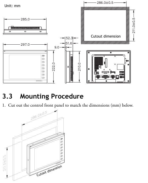
Size and Weight: Front Panel (W × H × D): 297.0 × 222.0 × 9.0mm; Installation Depth: 51.6mm; Hole Size: 286.0 × 211.0mm; Weight: 1.9kg
Storage and Memory Flash ROM 8MB, RAM 16MB, Battery Backup Memory 512KB (Data/Recipe Storage), CF Card Interface (Extended Storage)
32-bit RISC CPU with processor and clock; Real time clock (RTC, powered by lithium battery)
Environmental adaptability: working temperature of 0-50 ° C, storage temperature of -10-60 ° C; humidity of 20-90% RH (non condensing); Vibration tolerance (10~55Hz, 0.5mm displacement, 2 hours in each three-axis direction); Impact resistance (10G, 11ms, 3 times in each three-axis direction)
Certification standards CE certification (EN61000-6-4, EN61000-6-2)
2. Core component description (front/rear panel)
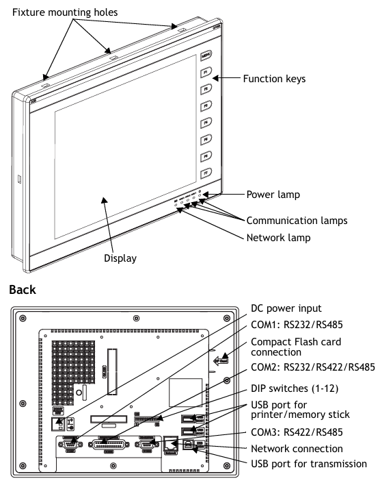
Front panel: includes fixed mounting holes, 8 function keys (1 menu key+7 F1~F7 keys), power indicator light, communication indicator light, network indicator light, 10.4-inch touch screen;
Rear panel: 24V DC power input interface, 3 communication ports (COM1~COM3), Ethernet interface, 2 USB host ports (for printer/USB flash drive), 1 USB device port (for data transmission), CF card interface, 12 bit DIP switch (for configuring working mode and communication parameters).
Installation process (including key steps)
1. Inspection of packaging list
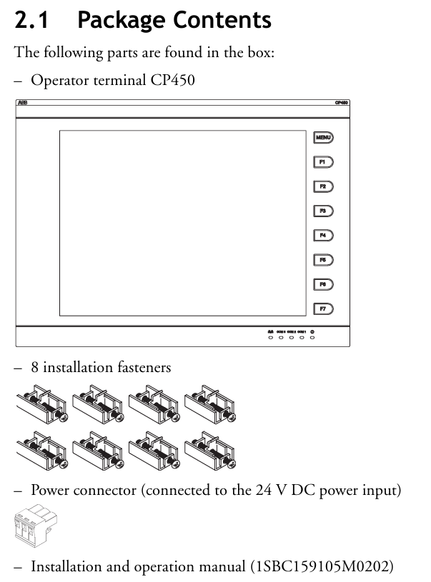
After unpacking, it is necessary to confirm that the following components are included. If they are missing, please contact the supplier:
1 CP450 operator terminal;
8 installation fasteners;
1 24V DC power connector (pre installed on the device);
One installation and operation manual (1SBC159105M0202).
2. Opening and fixing
Panel perforation: Drill holes on the control front panel according to the size (286.0 ± 0.5mm × 211.0mm), ensuring that the edges are flat and free of burrs;
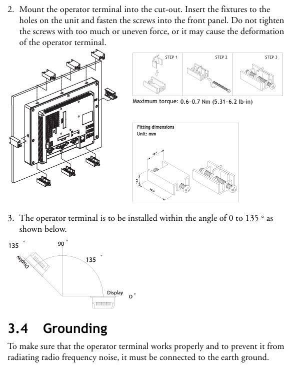
Equipment embedding: Insert CP450 into the opening and fix it to the front panel with the built-in fasteners (screws) of the equipment, with a torque controlled at 0.6~0.7 Nm (5.31~6.2 lb in), to avoid uneven force that may cause deformation of the equipment;
Installation angle: The installation angle of the equipment should be within the range of 0~135 ° (based on the display screen) to ensure the operating field of view and heat dissipation effect.
3. Grounding and power wiring
Grounding operation: Connect the grounding cable from the power connector on the rear panel of the device to an independent grounding point, ensuring that the grounding resistance is ≤ 100 Ω;
Power wiring: After disconnecting the power supply, remove the screw of the power connector, insert the stripped 24V DC wire (positive and negative poles distinguished), tighten the screw, and plug it back into the device power input interface. Copper conductors must be used and meet the wire diameter requirements (refer to safety specification 2.3).
4. Wiring requirements
Communication cables should be routed separately from power cables to avoid electromagnetic interference;
All communication cables must use shielded cables to reduce the impact of noise.
DIP switch configuration (core function switching)
The 12 bit DIP switches (SW1-SW12) on the rear panel of CP450 are used to configure working modes, communication parameters, password requirements, etc. The key switch functions are shown in the table below (switches not labeled as "reserved" must be strictly set according to requirements):
Specific setting instructions for DIP switch function classification
SW3~SW4 working mode - ON+ON: run user applications; -ON+OFF: Run the aging test program; -OFF+ON: Update BIOS; -OFF+OFF: Run the bench test program
SW5 communication parameter source - ON: communication parameters defined using the device configuration interface; -OFF: Communication parameters defined using CP400Soft software
SW6 power on password requirement - ON: After the power on self-test, the password needs to be entered; -OFF: No password required for startup
SW7 system menu display - ON: After self-test, the system menu is displayed; -OFF: Run the user application directly without displaying the system menu
SW8 default user level - ON: When starting up without a password, the default user level is 1 (highest privilege); -OFF: Default level 9 (minimum permission)
SW10 COM2 port mode - ON: COM2 is in RS485 mode; -OFF: COM2 is in RS422 mode
SW11 COM3 port mode - ON: COM3 is in RS485 mode; -OFF: COM3 is in RS422 mode
SW1,2,9,12 retain no functionality, no need to set
Communication port configuration
CP450 provides three serial communication ports (COM1~COM3), one Ethernet port, and one USB port, supporting flexible connections with controllers and third-party devices. The key parameters are as follows:
1. Serial communication ports (COM1~COM3)
Port interface type supports protocol pin function (core) adaptation scenarios
COM1 9-pin female head RS232/RS485- RS485+(1 pin), RS485- (6 pins); -RS232 RXD (2-pin), TXD (3-pin), GND (5-pin) are connected to controllers (such as PLCs) and simple peripherals
COM2 25 pin female head RS232/RS422/RS485- RS485+/RS422 TX+(14 pins), RS485-/RS422 TX - (15 pins); -RS232 TXD (2-pin), RXD (3-pin) for connecting multiple devices and long-distance communication
COM3 9-pin female head RS422/RS485- RS485+/RS422 TX+(1 pin), RS485-/RS422 TX - (6 pins); -RS422 RX+(4-pin), RX - (9-pin) long-distance, high stability communication
Attention: The port mode needs to be matched with the DIP switch (if COM2 is RS485, set SW10=ON), otherwise communication will fail.
2. Other communication interfaces
Ethernet port: only supported by CP450 T-ETH model, used for high-speed network communication, suitable for industrial Ethernet scenarios;
USB interface: 2 USB host ports (for connecting printers and USB drives for data storage or printing), 1 USB device port (for connecting to a PC to transfer applications or recipes);
CF card interface: used for extended storage, can store application backup, recipe data, etc.
Core operational functions (including debugging and maintenance)
1. Self Test
After the device is powered on, it automatically performs hardware self-test and the screen displays the test results. The following items should be focused on:
Key detection contents: RAM, battery status, BIOS checksum, firmware checksum, application checksum, communication ports (COM1~COM3), real-time clock (RTC);
Fault handling: If a certain item displays "Failed", follow the prompts to troubleshoot (such as firmware/application verification failure requiring re download; communication port failure requiring checking wiring and DIP switch);
First use: The real-time clock (RTC) needs to be manually reset to ensure time synchronization.
2. System menu operation (SW7 needs to be set to ON)
After self checking, enter the system menu and provide 5 core functions that need to be operated through the touch screen or function keys:
System menu command function description
Link establishes communication connections between devices and external devices (such as PCs, other CP450s)
F2- Configure real-time clock (date, time) and communication parameters (baud rate, data bits, stop bits, etc.) using the directional keys to select fields and the ± key to adjust values
F3- Copy copies the application program of the current device to another CP450, requires connecting the download cable and entering the password
F4- Set calibration touch screen (touch the top left/bottom right corner and center of the screen), this operation will clear RAM data
F5- Run the user application and exit the system menu
3. Application download and upload
(1) Download the application (PC → CP450)
Hardware connection: Use TK401 cable to connect the RS232 port of the PC to COM1 of CP450, or use TK402 cable to connect COM2 (power-off wiring required);
Switch settings: Set SW7 to ON (display system menu), SW5 to be set according to the parameter source (set to ON on the device end and OFF on the software end);
Software operation: Open CP400Soft, load the application and compile it (modifications must be recompiled), select "Application/Download Firmware/Application" for the first download, and select "Application/Download Application" for subsequent downloads;
Progress monitoring: The screen displays "Programming application...", and after completion, press F5 Run to run the application.
(2) Upload application (CP450 → PC)
Connection and settings: Follow steps 1-2 of the download process to ensure that the communication parameters match;
Software operation: Select "File/Upload Application" in CP400Soft and save it as * AF6 file, enter the password set in CP400Soft (see 7.10);
File conversion: After uploading, you need to open the file through "File/Recreate Source" and save it as * V6F format, used for subsequent modifications and maintenance.
Attention: The application must be run once before the first upload, otherwise the upload function will be disabled.
4. Recipe upload/download
The formula is used to store production parameters (such as process settings), and the operation process is as follows:
Upload recipe: Set SW7 to ON, select "File/Upload Recipes" in CP400Soft, and save as * RCP file;
Download Recipe: Open the application containing the recipe in CP400Soft, select "File/Download Recipes", and choose * RCP file, run F5 Run after completion;
Prerequisite: The formula length and quantity must be defined in the application, and the existing formula format must be uploaded before editing a new formula.
- YOKOGAWA
- Reliance
- ADVANCED
- SEW
- ProSoft
- WATLOW
- Kongsberg
- FANUC
- VSD
- DCS
- PLC
- man-machine
- Covid-19
- Energy and Gender
- Energy Access
- Renewable Integration
- Energy Subsidies
- Energy and Water
- Net zero emission
- Energy Security
- Critical Minerals
- A-B
- petroleum
- Mine scale
- Sewage treatment
- cement
- architecture
- Industrial information
- New energy
- Automobile market
- electricity
- Construction site
- HIMA
- ABB
- Rockwell
- Schneider Modicon
- Siemens
- xYCOM
- Yaskawa
- Woodward
- BOSCH Rexroth
- MOOG
- General Electric
- American NI
- Rolls-Royce
- CTI
- Honeywell
- EMERSON
- MAN
- GE
- TRICONEX
- Control Wave
- ALSTOM
- AMAT
- STUDER
- KONGSBERG
- MOTOROLA
- DANAHER MOTION
- Bentley
- Galil
- EATON
- MOLEX
- Triconex
- DEIF
- B&W
- ZYGO
- Aerotech
- DANFOSS
- KOLLMORGEN
- Beijer
- Endress+Hauser
- schneider
- Foxboro
- KB
- REXROTH
- YAMAHA
- Johnson
- Westinghouse
- WAGO
- TOSHIBA
- TEKTRONIX
- BENDER
- BMCM
- SMC
- HITACHI
- HIRSCHMANN
- XP POWER
- Baldor
- Meggitt
- SHINKAWA
- Other Brands
- UniOP
- KUKA
- IBA
- Beckhoff
- ADLINK
-
ADLINK HPCI-14S12U - Industrial Control Backplane 12PCI Backplane PCI-14S Passive Backplane
-
ADLINK PCIe-GIE74C - image acquisition card 4-CH GigE Vision PoE+ Frame Grabber
-
ADLINK PCI-8164 - control card 4-Axis Advanced Motion Controller Board
-
ADLINK PCIe-U304 - 4 Port USB3 PCIe Frame Grabbers USB Screw Hole Card
-
ADLINK PCI-9112 - Multi-Function Data Acquisition Card DAQ Card
-
ADLINK PCI-7432 - 51-12013-0A50 4-CH Isolated Numérique I/O PCI Cartes Digital I/O Card
-
ADLINK PCA-6106P3-0C1 REV.C1 - backplane 6-Slot Passive Backplane Board
-
ADLINK PCI-7224 - 24-CH Opto-Isolated Digital I/O PCI Board
-
ADLINK CPCI-7433R(G) - Digital Input Board Rear I/O CompactPCI Card
-
ADLINK EBP-13E4 - 51-46703-0A30 Industrial PC Backplane Passive Backplane
-
ADLINK PCIE-HDV62 - Image acquisition card High Definition Video Frame Grabber
-
ADLINK EBP-13E4 - 51-46703-0A30 Industrial Backplane Board Passive Backplane
-
ADLINK 90111-B1 / CPCI-6770 - PCB CPU MODULE CompactPCI Single Board Computer
-
ADLINK PCI-7248 - DATA ACQUISITION PCI CARD 48-CH Parallel Digital I/O Board
-
ADLINK PCI-7230 - 51-12003-0a50 board PCI7230 32-CH Isolated Digital I/O Card
-
ADLINK PCI2A000CB - 51-20000-0B30 Multi-Function DAQ Card Baseboard
-
ADLINK PCI-8134-005 - 4-Axis Motion Controller Card
-
ADLINK PCI-7224 - 24-CH Opto-Isolated Digital I/O PCI Card
-
ADLINK PCI-7434 - 64-CH Isolated Digital Output Card
-
ADLINK PCI-8132 - motion control card 2-Axis Servo & Stepper Controller
-
ADLINK PCI-8134 - Motion Controller PCI Card 4-Axis Controller Board
-
ADLINK PCI-8164 - Motion Control Card 51-12406-0A40 4-Axis Controller
-
ADLINK 51-12001-0C20 - Circuit Board Data Acquisition Interface Module Hardware
-
ADLINK NuPR0-840 - industrial control motherboard Full-Size PICMG CPU Board
-
ADLINK PCI-7444 - 51-12023-0A10 card 128-CH Isolated Digital Output Board
-
ADLINK PCI-1612B - data acquisition card 4-Port RS-232/422/485 Serial Communication Card
-
ADLINK PCI-6208V 009 - 8/16-CH 16-Bit Analog Output Cards PCB-I-E-482=6BX3
-
ADLINK NUPRO-935A/LV - industrial control motherboard Full-Size PICMG SBC Board
-
ADLINK PCI-9114DG - Multi-Function DAQ Card Data Acquisition PCI Card
-
ADLINK ACL-7130 - Data acquisition card Isolated Digital I/O Board
-
ADLINK ABX-6300D-4E1-BP - board ABX6300D4E1BP Video Interface Expansion Card
-
ADLINK CPCI-6940 - CPCI-6940/D1539/M16-0(EA)-000E 6U CompactPCI Processor Board
-
ADLINK NuPRO-760 - industrial control motherboard Half-Size PICMG SBC CPU Board
-
ADLINK IMB-M42H (G)-0020 - industrial control motherboard LGA1155 Micro-ATX Mainboard
-
ADLINK RTV-24 / PCI-MP4S - 51-12519-1C30 4-Channel Real Time Video Capture Board
-
ADLINK PCI-8134 - 4-Axis Servo & Stepper Motion Controller Card
-
ADLINK MXC-6101D - V.PC000.002.ST.00 Box PC Configurable Embedded Computer
-
ADLINK PCI-8134A - 51-12421-0A10 Motion Control Card 4-Axis Controller Card
-
ADLINK DIN-100S / DIN-100SA1 - Technology SCSI-II TB 100-PIN Terminal Block Board
-
ADLINK DIN-812M001 / DIN812M001 - 51-14034-0A1 51140340A1 Terminal Module Breakout Interface
-
ADLINK PCI-8164 - Servo motion control 4-Axis Advanced Controller Card
-
ADLINK PCIe-GIE64 - Acquisition card GigE Vision PoE+ Frame Grabber
-
ADLINK M-302 - Industrial control motherboard ATX PC Board Mainboard
-
ADLINK PCI-8134 - Motion Controller PCI Card 4-Axis Controller Board
-
ADLINK PCI-RTV24 - Image capture card Analog Video Frame Grabber
-
ADLINK PCI-8102 - Motion control card 2-Axis Servo & Stepper Controller Board
-
ADLINK PCI-9112 REV.B1 - Card Multi-Function Data Acquisition Card
-
ADLINK HSI-DI32-M-N / HSL-TB32-M-DIN - Discrete I/O MODULE Distributed Automation Module System
-
ADLINK PCI-7296 - IO card REV.A3 96-CH Parallel Digital I/O Card
-
ADLINK DIN-814P-A4 / 814Y - terminal board Motion Control Interface Block
-
ADLINK DIN-814P-A4 - 51-14056-0A10 PCB-I-E-2736=ZA01 Screw Terminal Board Breakout
-
ADLINK M-322 - motherboard Industrial Control Computer Mainboard
-
ADLINK NUPRO-406 REV:B1 - industrial control motherboard Full-Size PICMG CPU Board
-
ADLINK AMP-204C - card DSP-Based 4-Axis Advanced Pulse-Train Controller
-
ADLINK HPCI14S REV.B1 - industrial computer baseboard 14-Slot Passive Backplane
-
ADLINK PCI-7250 - 8-CH Relay Output & 8-CH Isolated DI PCI Card
-
ADLINK EBP-13E2 - baseplate Passive Backplane Industrial Computer Chassis Board
-
ADLINK LPCI-3488A - PCI-GPIB card 51-12801-0A30 acquisition card IEEE-488 Interface Board
-
ADLINK PCI-6216V-GL - 51-12201-0C30 16-CH 16-Bit Voltage Analog Output Card
-
ADLINK ACL-8454 - 16-CH Isolated Digital I/O & 4-CH Counter Card
-
ADLINK HPCI-9S7U - backplane Passive Backplane Compatible with NuPRO-A301 852 841 842
-
ADLINK DAQ-2010-007 - Simultaneous-Sampling Multi-Function Data Acquisition Card
-
ADLINK MP-C154 - 51-64205-0A10 Motion Control Card 4-Axis Controller Board
-
ADLINK MXE-202/mSSD16B/WiFi-BT - Matrix Rugged I/O Platform Embedded Fanless Computer
-
ADLINK CM-920-R-17 - PC/104-Plus Single Board Computer Module Intel Celeron M
-
ADLINK PCI-7250 NSMP - 8-CH Relay Output & 8-CH Isolated DI Card
-
ADLINK PCI-8164 - 4-Axis Motion Controller PCI Card W/ Cable and Breakout Box
-
ADLINK EMX-100 - Ethernet-based 4-axis Motion Controllers Distributed Motion Module
-
ADLINK PCI-8134A - Press control card 4-Axis Motion Controller Board
-
ADLINK M-845EG REV:3.2 - industrial motherboard Pentium 4 Socket 478 Micro-ATX
-
ADLINK PCI-9114A Rev A2 DG - card High-Resolution Multi-Function Data Acquisition Board
-
ADLINK IEC-915GV - REV 1.1 Industrial motherboard Socket 478 CPU Board
-
ADLINK PCI-9111DG(G) - Data Acquisition Card Multi-Function DAQ Card
-
ADLINK HPCI-15S10 REV:B2 - Industrial computer base plate Passive Backplane Board
-
ADLINK NuPR0-840 / NuPR0-840DV - industrial control motherboard Full-size PICMG CPU Board
-
ADLINK RTV-24 / PCI-MP4S - 51-12519-1C30 4-Channel Real Time Video Capture Board
-
ADLINK NUPRO-780 - industrial control motherboard Pentium III Single Board Computer
-
ADLINK PCI-7296 - 0050 card 96-CH Opto-Isolated Parallel DIO Card Set
-
ADLINK NUPRO-780 - industrial control motherboard PICMG Full-Size SBC
-
ADLINK PCI-7248 - 51-12006-0A3 002 Pci 7248 48-CH Parallel Digital I/O Card
-
ADLINK cPCI-6626 - 6U CompactPCI 2.0 Blades i7-2710QE PCB-I-E-2570=9N41
-
ADLINK MXC-6322D(G) - Industrial Fanless Computer
-
ADLINK cPCI-8168-004 - CompactPci NulPC Motion Control Board 51-36402-0A3
-
ADLINK CPCI-7300[G] - COMPACTPCI Digital I/O Card Data Acquisition
-
ADLINK CPCI-6626/2710/M4G - COMPACTPCI COMPUTER BOARD
-
ADLINK cPCI-8168-009 - cPCI NulPC Motion Control Board
-
ADLINK cPCI-6626/2710/M4G - VME CPU Board Computer Board
-
ADLINK CPCI-R6200(G)-0040 - COMPACTPCI CONTROL BOARD
-
ADLINK CPCI-3840/PM18/M1G(G)-3650 - COMPACTPCI CPU Module Single Board Computer
-
ADLINK cPCI-7248 - 48-CH Opto-22 Compatible Digital I/O Module
-
ADLINK DLAP-211-JNX - NVIDIA Jetson Xavier NX Edge AI Inference Platform
-
ADLINK cPCI-3544 - Series 4-Port RS-422/485 Isolated Serial Communications Card
-
ADLINK CM1-86DX3 - PC/104 SBC Stanley Vortex86DX3 CPU 2GB Ram
-
ADLINK DLAP-211-JNX - NVIDIA Jetson Xavier NX Edge AI Inference Platform
-
ADLINK cPCI-3544 - Series 4-Port RS-422/485 Isolated Serial Communications Card
-
ADLINK CM1-86DX3 - PC/104 SBC Stanley Vortex86DX3 CPU 2GB Ram
-
ADLINK PCI-7433 - switch value acquisition card Isolated Digital Input Card
-
ADLINK PCI-9112 - 51-12252-0D20 Multi-Function Data Acquisition Card
-
ADLINK NUPRO-A301 REV:1.4 - industrial control motherboard PICMG Full-Size SBC
-
ADLINK 51-18502-0A10 - Frame Grabber Image Acquisition Interface Card
-
ADLINK PCI-7296 - 51-12009-0A50 PCB-I-E-925=6DX1 96-CH Parallel Digital I/O Board
-
ADLINK PCI-8132 GP A2 - Motion Control Card 2-Axis Servo & Stepper Controller
-
ADLINK PCI-7442 - switch quantity card data acquisition card 64-CH Isolated Card
-
ADLINK HPX-13S4 - baseboard PICMG 1.3 Passive Backplane Chassis Baseplate
-
ADLINK NuPRO-590 / NTC-567-ZM-F36 - Single Board Computer PCB-I-E-1853=9L21 Half-Size SBC
-
ADLINK PCIe-8332 - 16-axis plate Motion Control Hardware Card
-
ADLINK NuPRO-775 REV.B1 - motherboard Pentium 4 Full-Size PICMG SBC
-
ADLINK PXI-3920 - Embedded Controller 3U PXI cPCI System Intelligence Board
-
ADLINK PCI-8134 - driver card motion control card 4-Axis Controller Board
-
ADLINK HSL-DI32-M-N-011 / HSL-TB32-M-DIN - Digital Input & Base Module PLC Distributed I/O System
-
ADLINK PCI-6216V-206 / PCI-208V 009 - 16 CH 16bit analog output card
-
ADLINK NuPro-E330 - 51-41805-0A20 PCB Single Board Computer Host Board
-
ADLINK PCI-1622C - Card 8-Port RS-232/422/485 PCI Serial Communication Board
-
ADLINK PCIe-7432 - 51-18402-0A10 Carte PCIe Avec Plage D'Entrée Élevée Isolated DIO Card
-
ADLINK PCI-7250 - PCI Acquisition Card 8-CH Relay Output Isolated DI Card
-
ADLINK PCI-7230 - 32-CH Isolated Digital I/O Card
-
ADLINK PCI-8164 - PCB 4-Axis Motion Controller Card
-
ADLINK PCI-7854 - Collection card High-Speed Link Distributed Motion Controller
-
ADLINK NuPRO-935A/LV - industrial control computer motherboard Full-Size PICMG SBC
-
ADLINK IMB-M40H - motherboard IH61-AA4 1155 LGA1155 Micro-ATX Mainboard
-
ADLINK PCI-7248 - Linhua 51-12006-0A40 48-CH Parallel Digital I/O Card
-
ADLINK HPCI-14S12U - Linhua industrial computer baseboard Passive Backplane
-
ADLINK PCI-8132 Rev.A2 - 2-Axis Servo & Stepper Motion Controller Card
-
ADLINK ACL-8111 - ISA card Multi-Function DAQ Card
-
ADLINK ACL-8111 - ISA card Multi-Function Data Acquisition Board
-
ADLINK PCI-7200 REV.A3 - Digital I/O card 12MB/s High-Speed Parallel Digital I/O
-
ADLINK PCI-7296 REV.A3 - 96-CH High-Density Opto-Isolated DIO Card
-
ADLINK PCI-7434 - 64-CH Isolated Digital Output Card

K-JIANG

Add: Jimei North Road, Jimei District, Xiamen, Fujian, China
Tell:+86-15305925923