
K-WANG


KBAC series adjustable frequency drive
KBAC series adjustable frequency drive
Product Overview
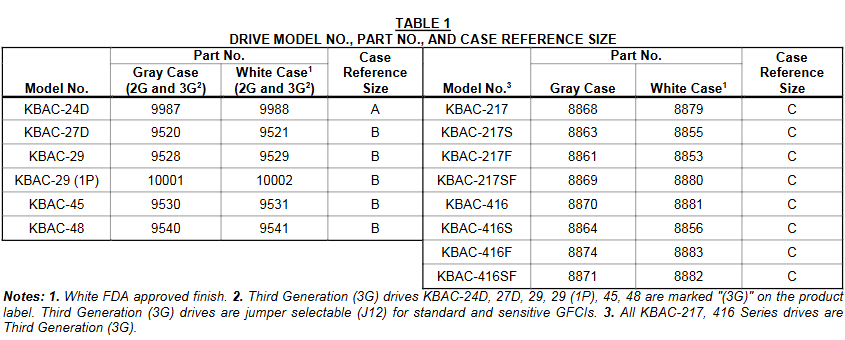
The KBAC series adjustable frequency drive is suitable for three-phase AC motors and has a NEMA 4X/IP65 protection level. It can achieve waterproof and dustproof performance and is suitable for indoor and outdoor flushing environments. Supports voltages of 208-230V and 400/460V, with a frequency of 50/60Hz, capable of driving motors ranging from sub fractional horsepower to 10 horsepower. It also has variable speed, soft start function, and electronic motor overload protection. It is compatible with AC inputs of 115V, 208/230V, and 400/460V, and is available in 2G and 3G models. Some 3G models have product labels labeled "(3G)", and both KBAC-217 and 416 series are 3G models.
Core functions and features
(1) Standard Features
Shell: Industrial grade die cast aluminum shell with hinged cover, available in two surface treatments: dark gray and FDA approved white.
Convenience of operation: No programming required, adjustable potentiometer and jumper settings can be made, and most application scenarios are pre-set at the factory.
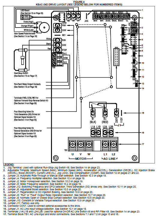
Selection function: including motor horsepower selection jumper (J2), switch frequency and GFCI selection jumper (J12, only 3G model), diagnostic LED light (power and status indication), operation/fault relay output contact, start stop switch, barrier terminal block, etc. The driver output frequency can also be selected through jumper to achieve a maximum motor speed of twice the rated speed, with power-off recovery function and zero speed holding torque, as well as multiple adjustable fine adjustment potentiometers.
Jumper selection: covering AC input voltage (only J1 for KBAC-24D and 27D), motor horsepower (J2), automatic power-off recovery/manual start (J3), frequency multiplier (J4), motor frequency (J5), fixed/adjustable boost (J6), regeneration/injection braking (J7), operation/fault output relay operation (J8), normally open/normally closed stop contact (J9), constant torque/variable torque (J10), switching frequency and GFCI (only J12 for 3G models).
(2) Performance characteristics
Power Start ™: Can provide over 200% starting torque to ensure smooth start-up under high friction loads.
Slip compensation: With static automatic tuning and boost function, it achieves excellent load regulation over a wide speed range.
Speed range: The speed ratio can reach 60:1.
(3) Protection features
Motor Overload Protection (I2t): With RMS current limitation, it can prevent motor burnout, avoid false tripping, and is certified by UL as an electronic overload protector for motors.
Electronic Surge Current Limitation (EICL) ™): Eliminate harmful AC input surge currents during startup.
Other protections: equipped with short-circuit protection (shutdown in case of motor phase to phase short circuit), regenerative protection (to avoid tripping caused by high bus voltage due to rapid deceleration of high inertia load), overvoltage and undervoltage protection (shutdown in case of input voltage exceeding the range), MOV input transient suppression (to protect driver components from damage caused by input voltage spikes), and microcontroller self-monitoring and automatic restart functions.
Installation points
(1) Installation method
It is recommended to install it vertically on a flat surface to ensure sufficient ventilation, and reserve enough space below for wiring. If installed inside the casing, it is necessary to ensure that the casing size is sufficient for heat dissipation, the ambient temperature does not exceed 40 ° C (104 ° F), and it cannot be used in explosion-proof environments. The installation must be firm.
(2) Communication input circuit breaker
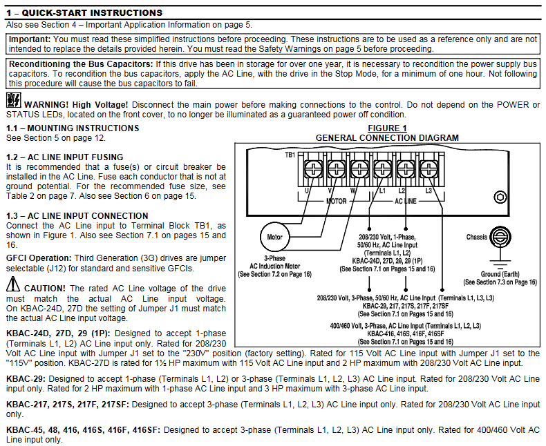
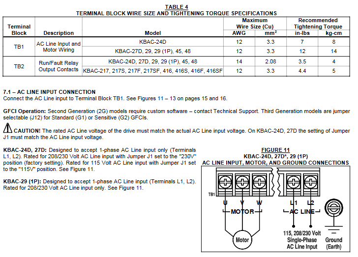
The driver does not have a built-in circuit fuse, and a fuse (such as Littelfuse 312/314, Bus ABC, or equivalent) or circuit breaker must be connected in series with each non grounded wire according to electrical specifications. The neutral wire or grounding wire should not be blown. Please refer to Table 2 (page 7) for specific fuse specifications.
(3) Electrical connection
Wiring specifications: It must comply with the National Electrical Code and applicable local regulations. Wiring should be carried out after power failure to ensure correct grounding. When remotely connecting potentiometers, switches, etc., it is recommended to install signal isolators to avoid high voltage risks.
Communication input connection: The wiring terminals of different models of drivers are different, and they need to be connected according to the model. The rated AC input voltage of the driver needs to match the actual input voltage, and some models need to set corresponding jumper wires.
Motor connection: The motor is connected to the U, V, and W terminals of TB1. The length of the motor cable should not exceed 100 feet (30 meters). If it exceeds this, a special reactor is required (technical support should be contacted), and the J2 jumper should be set to the corresponding motor horsepower level.
Grounding connection: The grounding wire (earth) should be connected to the green grounding screw, and the motor should also be properly grounded.
Other connections: including remote main speed potentiometer, remote start stop switch, automatic restart (requiring cancellation of start stop switch and hard wiring), voltage following (0-5V DC analog signal that needs to be isolated), enable circuit, operation/fault relay, etc., all have specific wiring methods and precautions.
(4) Bus capacitor repair
If the drive is stored for more than one year, it is necessary to apply AC input voltage in shutdown mode for at least 1 hour to repair the power bus capacitor, otherwise the capacitor may be damaged.
Operation and Debugging
(1) Start the program
After completing the jumper and fine adjustment potentiometer settings and wiring, connect the AC power supply, and the power (PWR) LED green light will turn on. Use the start stop switch to briefly place it in the "start" position to start the driver, and the motor will accelerate to the set speed. If the motor turns in the wrong direction, replace any two motor leads after powering off.
(2) Restart after malfunction
Drive monitoring includes five types of faults: undervoltage, overvoltage, motor short circuit, overload, and phase loss. After the faults are cleared, restart through the start stop switch; If the start stop switch is cancelled, the AC power supply needs to be disconnected and reconnected to restart. Partial faults (such as overvoltage) can be automatically restarted after the voltage returns to normal in automatic power-off recovery mode.
(3) Fine tuning potentiometer adjustment
Minimum speed (MIN): Factory set to 0% of the frequency setting, clockwise rotation can increase the minimum speed.
Maximum speed (MAX): Factory set to 100% of the frequency setting, counterclockwise/clockwise rotation can reduce/increase the maximum speed.
Acceleration (ACCEL): The factory setting is 1.5 seconds. Clockwise/counterclockwise rotation extends/shortens the acceleration time, and rapid acceleration may trigger the current limiting circuit to extend the acceleration time.
Decel: The factory setting is 1.5 seconds, and clockwise/counterclockwise rotation extends/shortens the deceleration time. In high inertia load applications, the deceleration time may be automatically extended. It is recommended to set the acceleration and deceleration time to 10 seconds or more for high inertia loads.
DECEL (Direct Current Injection Braking): Only when J7 is set to "INJ", this potentiometer is used to set the time for direct current to be applied to the motor. It is factory set to regenerative braking (J7 is set to "RG").
Slip Compensation (COMP): Factory set to 1.5 volts per hertz, clockwise/counterclockwise rotation increases/decreases slip compensation, and can be adjusted through specific steps to achieve speed stability under different loads.
Motor overload (I2t) and RMS current limit (CL): The factory setting is 160% of the rated current of the driver. Clockwise/counterclockwise rotation increases/decreases the current limit, which needs to be adjusted step by step and cannot exceed the rated current of the motor by 160% to avoid motor overheating.
Boost (BOOST): The factory setting is a fixed boost (J6 is set to "FIX"), which can be adjusted when J6 is set to "ADJ". It operates in the frequency range of 0-15Hz and needs to be adjusted step by step to avoid overheating and damage to the motor winding caused by excessive boost.
Jog: An optional run stop jog switch kit is required, which can set the jog speed. When the switch is in the "jog" position, the speed is set by the fine adjustment potentiometer, and when in the "run" position, the speed is set by the main speed potentiometer.
Diagnosis and fault handling
(1) Diagnostic LED
Power LED (PWR): When the AC power is turned on, the green light will turn on. It should not be used as a basis for power outage. Before maintenance, make sure that the main power switch or circuit breaker is disconnected.
Status LED (ST): It is a three color LED with different flashing frequencies and colors corresponding to different operating states and faults, such as normal operation (green light flashing slowly), overload (red light constantly on when 120% -160% full load; red light flashing rapidly when timeout trips), short circuit (red light flashing slowly), undervoltage (red and yellow light flashing rapidly), overvoltage (red and yellow light flashing slowly), stop (yellow light constantly on), standby (yellow light flashing slowly, only when installing forward and reverse switches), input phase loss (yellow light flashing rapidly, specific models), overheating trip (red and yellow light flashing rapidly, specific models), and the status will change accordingly after troubleshooting.
(2) Common fault handling
Overload fault: After clearing the fault, restart and check the motor current with an AC RMS ammeter. If the current limit is set too low, adjust it.
Overvoltage fault: In automatic power-off recovery mode, the driver automatically restarts after the voltage returns to normal.
Motor steering error: replace any two motor leads after powering off.
Other faults: troubleshoot according to the status LED indication, such as checking the motor wiring for short circuits, checking the input voltage for undervoltage/overvoltage, checking the input circuit for phase loss (specific model), and checking the heat dissipation for overheating (specific model).
Optional accessories
We offer a variety of optional accessories, including forward and reverse switch kits, AC line on/off switch kits, run stop jog switch kits, SIAC-PS signal isolator kits (available in 3G and 2G models), automatic/manual switch kits, SIAC-PS signal isolator and automatic/manual switch combination kits, AC line filter kits (available with "S" and "NS" suffixes, some models pre installed at the factory), liquid tight joint kits, etc. Different accessories are suitable for different models of drivers, and some accessories require specific installation methods to ensure liquid tightness or achieve corresponding functions.
- YOKOGAWA
- Reliance
- ADVANCED
- SEW
- ProSoft
- WATLOW
- Kongsberg
- FANUC
- VSD
- DCS
- PLC
- man-machine
- Covid-19
- Energy and Gender
- Energy Access
- Renewable Integration
- Energy Subsidies
- Energy and Water
- Net zero emission
- Energy Security
- Critical Minerals
- A-B
- petroleum
- Mine scale
- Sewage treatment
- cement
- architecture
- Industrial information
- New energy
- Automobile market
- electricity
- Construction site
- HIMA
- ABB
- Rockwell
- Schneider Modicon
- Siemens
- xYCOM
- Yaskawa
- Woodward
- BOSCH Rexroth
- MOOG
- General Electric
- American NI
- Rolls-Royce
- CTI
- Honeywell
- EMERSON
- MAN
- GE
- TRICONEX
- Control Wave
- ALSTOM
- AMAT
- STUDER
- KONGSBERG
- MOTOROLA
- DANAHER MOTION
- Bentley
- Galil
- EATON
- MOLEX
- Triconex
- DEIF
- B&W
- ZYGO
- Aerotech
- DANFOSS
- KOLLMORGEN
- Beijer
- Endress+Hauser
- schneider
- Foxboro
- KB
- REXROTH
- YAMAHA
- Johnson
- Westinghouse
- WAGO
- TOSHIBA
- TEKTRONIX
- BENDER
- BMCM
- SMC
- HITACHI
- HIRSCHMANN
- XP POWER
- Baldor
- Meggitt
- SHINKAWA
- Other Brands
- UniOP
- KUKA
- IBA
- Beckhoff
-
ADLINK cPCI-6626 - 6U CompactPCI 2.0 Blades i7-2710QE PCB-I-E-2570=9N41
-
ADLINK MXC-6322D(G) - Industrial Fanless Computer
-
ADLINK cPCI-8168-004 - CompactPci NulPC Motion Control Board 51-36402-0A3
-
ADLINK CPCI-7300[G] - COMPACTPCI Digital I/O Card Data Acquisition
-
ADLINK CPCI-6626/2710/M4G - COMPACTPCI COMPUTER BOARD
-
ADLINK cPCI-8168-009 - cPCI NulPC Motion Control Board
-
ADLINK cPCI-6626/2710/M4G - VME CPU Board Computer Board
-
ADLINK CPCI-R6200(G)-0040 - COMPACTPCI CONTROL BOARD
-
ADLINK CPCI-3840/PM18/M1G(G)-3650 - COMPACTPCI CPU Module Single Board Computer
-
ADLINK cPCI-7248 - 48-CH Opto-22 Compatible Digital I/O Module
-
ADLINK DLAP-211-JNX - NVIDIA Jetson Xavier NX Edge AI Inference Platform
-
ADLINK cPCI-3544 - Series 4-Port RS-422/485 Isolated Serial Communications Card
-
ADLINK CM1-86DX3 - PC/104 SBC Stanley Vortex86DX3 CPU 2GB Ram
-
ADLINK DLAP-211-JNX - NVIDIA Jetson Xavier NX Edge AI Inference Platform
-
ADLINK cPCI-3544 - Series 4-Port RS-422/485 Isolated Serial Communications Card
-
ADLINK CM1-86DX3 - PC/104 SBC Stanley Vortex86DX3 CPU 2GB Ram
-
ADLINK PCI-7433 - switch value acquisition card Isolated Digital Input Card
-
ADLINK PCI-9112 - 51-12252-0D20 Multi-Function Data Acquisition Card
-
ADLINK NUPRO-A301 REV:1.4 - industrial control motherboard PICMG Full-Size SBC
-
ADLINK 51-18502-0A10 - Frame Grabber Image Acquisition Interface Card
-
ADLINK PCI-7296 - 51-12009-0A50 PCB-I-E-925=6DX1 96-CH Parallel Digital I/O Board
-
ADLINK PCI-8132 GP A2 - Motion Control Card 2-Axis Servo & Stepper Controller
-
ADLINK PCI-7442 - switch quantity card data acquisition card 64-CH Isolated Card
-
ADLINK HPX-13S4 - baseboard PICMG 1.3 Passive Backplane Chassis Baseplate
-
ADLINK NuPRO-590 / NTC-567-ZM-F36 - Single Board Computer PCB-I-E-1853=9L21 Half-Size SBC
-
ADLINK PCIe-8332 - 16-axis plate Motion Control Hardware Card
-
ADLINK NuPRO-775 REV.B1 - motherboard Pentium 4 Full-Size PICMG SBC
-
ADLINK PXI-3920 - Embedded Controller 3U PXI cPCI System Intelligence Board
-
ADLINK PCI-8134 - driver card motion control card 4-Axis Controller Board
-
ADLINK HSL-DI32-M-N-011 / HSL-TB32-M-DIN - Digital Input & Base Module PLC Distributed I/O System
-
ADLINK PCI-6216V-206 / PCI-208V 009 - 16 CH 16bit analog output card
-
ADLINK NuPro-E330 - 51-41805-0A20 PCB Single Board Computer Host Board
-
ADLINK PCI-1622C - Card 8-Port RS-232/422/485 PCI Serial Communication Board
-
ADLINK PCIe-7432 - 51-18402-0A10 Carte PCIe Avec Plage D'Entrée Élevée Isolated DIO Card
-
ADLINK PCI-7250 - PCI Acquisition Card 8-CH Relay Output Isolated DI Card
-
ADLINK PCI-7230 - 32-CH Isolated Digital I/O Card
-
ADLINK PCI-8164 - PCB 4-Axis Motion Controller Card
-
ADLINK PCI-7854 - Collection card High-Speed Link Distributed Motion Controller
-
ADLINK NuPRO-935A/LV - industrial control computer motherboard Full-Size PICMG SBC
-
ADLINK IMB-M40H - motherboard IH61-AA4 1155 LGA1155 Micro-ATX Mainboard
-
ADLINK PCI-7248 - Linhua 51-12006-0A40 48-CH Parallel Digital I/O Card
-
ADLINK HPCI-14S12U - Linhua industrial computer baseboard Passive Backplane
-
ADLINK PCI-8132 Rev.A2 - 2-Axis Servo & Stepper Motion Controller Card
-
ADLINK ACL-8111 - ISA card Multi-Function DAQ Card
-
ADLINK ACL-8111 - ISA card Multi-Function Data Acquisition Board
-
ADLINK PCI-7200 REV.A3 - Digital I/O card 12MB/s High-Speed Parallel Digital I/O
-
ADLINK PCI-7296 REV.A3 - 96-CH High-Density Opto-Isolated DIO Card
-
ADLINK PCI-7434 - 64-CH Isolated Digital Output Card
-
ADLINK M-342 - atx motherboard Industrial PC Mainboard
-
ADLINK NuPRO-935ADV (A) 1.9 - CPU Board Intel Core 2 Quad CPU Q9500 2.83GHz PICMG Board
-
ADLINK NUPRO-935A/DV - motherboard dual network port 51-41802-0A10 CPU Board
-
ADLINK PCI-RTV24 - image capture card Analog Video Frame Grabber Board
-
ADLINK HPX-13S4 - device baseboard PICMG 1.3 Passive Backplane Chassis Baseplate
-
ADLINK PCI-8134A - control card 4-Axis Motion Controller Card
-
ADLINK ACL-7130 REV. B2 - industrial control capture card Isolated Digital I/O Board
-
ADLINK EBP-13E2 - Industrial Backplane Board Passive Backplane Baseboard
-
ADLINK NuPRO-935ADV (A) 1.9 - CPU Board Intel Core 2 Quad CPU Q9500 2.83GHz PICMG SBC
-
ADLINK PCI-8134A - motion control card 4-Axis Pulse-Train Controller Card
-
ADLINK PCI-9112 REV A.1 - Multi Function DA&C Board Data Acquisition Card
-
ADLINK 51-12001-0C20 - Circuit Board Multi-Function Data Acquisition Hardware
-
ADLINK PCI-7300A - 80-CH High-Speed Digital I/O Card
-
ADLINK PCI-7230 - 16-CH Isolated Digital Input Output Card
-
ADLINK DIN-814-GP - motion control module Interface Terminal Block
-
ADLINK NUPRO-A40H - 51-41807-1A20 Industrial Control Motherboard LGA1155
-
ADLINK PCI-7433 rev A2 - Isolated Digital Input Card
-
ADLINK NuPRO-780 - Pentium III 800 512 MB SBC NuPRO780 51-41309-0B2 Single Board Computer
-
ADLINK PCI-7853 / PCI-7854 - Acquisition card High-Speed Link Control Card
-
ADLINK NUPRO-852 / NUPRO-852LV - Industrial motherboard Full-Size PICMG CPU Board
-
ADLINK NuPRO-842LV/P - 51-41360-0B30 Industrial Motherboard Half-Size PICMG SBC
-
ADLINK PCI-FIW64 - 4/2 Channel IEEE1394B Image Capture Card Frame Grabber
-
ADLINK PCI-7851 Rev A1.1 - HSL system card High-Speed Link Master Controller
-
ADLINK PCI-7230 - 51-12003-0A50 card 32-CH Isolated Digital I/O Card
-
ADLINK NuPRO-841REV:1.0 - Industrial CPU Board Mainboard
-
ADLINK NuPRO-841 REV:1.0 - motherboard Industrial Control PC Mainboard
-
ADLINK PCI-8256 - 8-Axis Advanced Motion Control PCI Board
-
ADLINK PCI-6S / PCI6S - Backplane 6-Slot Passive Backplane Board
-
ADLINK PCI-7234 REV B3 - 32-CH Isolated Digital Output PCI Card
-
ADLINK PCI-8213 - HannStar MV-4 51-45003-0b4 Board
-
ADLINK PCI-7233 - 51-12004-0a20 board PCI7233 32-CH Isolated Digital Input Card
-
ADLINK PCI-7851 - 006 51-24003-0B20 High-Speed Link Master Motion Control Card
-
ADLINK PCI-7432 - 64-CH Isolated Digital I/O PCI Cards
-
ADLINK LPCI-3488 - Card Low Profile IEEE-488 GPIB Interface Card
-
ADLINK HPCI14S REV.B1 - industrial control computer base plate Passive Backplane
-
ADLINK NEON-1020 - Industrial camera Smart Camera Vision System
-
ADLINK PCI-7432 - Isolated Digital I/O PCI Card 64-CH
-
ADLINK Pcm-7250+ - 8-Ch Relay Outputs & 8-Ch Isolated DI Module PC/104
-
ADLINK CPCI-7841 - DUAL-PORT ISOLATED CAN INTERFACE CARD CompactPCI
-
ADLINK PCI-3488 / PCI-GPIB - PCI IEEE-488 GPIB Interface Card
-
ADLINK PCI-1711U - Card Multi-Function Data Acquisition Board
-
ADLINK NUPRO-A301 - REV:1.1 1.2 1.4 PICMG Full-Size Single Board Computer
-
Adlink DIN-50S-01 - PLOTECH 51-14024-0A40 50-pin Wiring Terminal Board
-
Chroma 52962 / 58183 - PXI Optical Spectrometer carrier adapter Card
-
ADLINK PCI-6208V - PCI DATA ACQUISITION & RECORDING CARD 8-CH Analog Output
-
ADLINK HSL-DI32-DB-N - Industrial Control Board Distributed Digital Input Module
-
ADLINK HSL-AO4-U - 4-CH HIGH SPEED LINK ANALOG OUTPUT MODULE Distributed I/O
-
ADLINK PCI-7396 - 0050 GP 51-12012-0B20 96-CH High-Speed Digital I/O Card
-
ADLINK NUPRO-935A/DV - 51-41802-0A10 motherboard Industrial CPU Single Board Computer
-
ADLINK PCI-9111 DG - Industrial Acquisition Card Multi-Function DAQ Card
-
ADLINK NuPRO-E315 - industrial computer motherboard Intel Atom SHB SBC
-
ADLINK NUPRO-406 REV:B1 - Industrial Control Motherboard Full-Size PICMG CPU Board
-
ADLINK NuPRO-E330 - motherboard Industrial Control System Host Board PICMG 1.3
-
ADLINK ACL-6128A 103 - 51-11002-1A4 2-CH Isolated Analog Output Card
-
XTRAMUS cPS-H325/AC - POWER SUPPLY NUSTREAMS 600 NETWORK TESTING EQUIPMENT Power Module
-
ADLINK DIN-814P-A4 - 51-14056-0A10 Terminal Block Motion Control Breakout Board
-
ADLINK TB-24P/24-01 - 24-Channel Card Terminal Breakout Board
-
ADLINK PCI-7251 - 51-12008-0A30 PCI7251 8-CH Relay Output Isolated Digital Input Card
-
ADLINK HSL-TB64-DIN REV A1 / HSL-DO32-DB-N - 2ea Board Breakout Terminal Board Distributed I/O Module
-
ADLINK NuPRO-865 REV 3.0 - industrial computer motherboard Full-Size PICMG SBC
-
ADLINK NUPRO-A40H - motherboard 51-41807-1A30 OSP H61 Industrial PC Mainboard
-
ADLINK LPCI-3488A - PCI Card 51-12801-0A30 GPIB Interface Card
-
ADLINK DIN-825-4P0 - 51-14085-0A30 Terminal Printed Circuit Board Breakout Block
-
ADLINK IMB-T10/D2550 V - MOTHER BOARD 80-PXG160-A1A01 IMB-T10-M2G-S32G Industrial Mainboard
-
ADLINK PCI-8144N - Motion Control card Stepper Motor Controller
-
ADLINK PCI-7433 - Digital acquisition card Isolated Digital Input Card
-
ADLINK PCI-9112 DG - Data Acquisition card 51-12252-0D20 Multi-Function DAQ
-
ADLINK IMB-M40H - motherboard IH61-AA4 1155 LGA1155 Micro-ATX Mainboard
-
ADLINK TB-24P/24-01 - Carte 24 voies Terminal Breakout Board Connector Module
-
ADLINK HSL-D16DO16-M-NN - Distributed Discrete Input Output I/O Module
-
ADLINK PCI-7248 - PCI CARD 51-12006-0A40 48-CH Parallel Digital I/O Board
-
ADLINK HSL-DI32-DB-N - Industrial Control Board Distributed I/O Digital Input Module
-
ADLINK PCI-7433 - Pci 7433 Isolated Digital Input Card
-
ADLINK PCI-6208V - 008 Data acquisition card 8-CH Analog Output Card
-
ADLINK IH61-AA4 - industrial motherboard LGA1155 Micro-ATX Mainboard
-
ADLINK PXI-3920 - PXI 3U cPCI Industrial Controller Embedded System CPU Board
-
ADLINK PCI-6308 - Analog Output DAQ Card Isolated Voltage Output Card
-
ADLINK PCI-7200 - data acquisition card REV.A3 High-Speed Parallel DIO Card
-
ADLINK NuPRO-E315 - Industrial Control Computer Motherboard PICMG 1.3 SHB SBC
-
ADLINK PCI-1610C - Card 4-Port Isolated RS-232 PCI Serial Communication Card

K-JIANG

Add: Jimei North Road, Jimei District, Xiamen, Fujian, China
Tell:+86-15305925923