
K-WANG


HIMA CPU 01 Controller Module
Storage and Execution: Stores the operating system (OS) and user programs, performs core functions such as logical operations, I/O signal processing, and security self checks.
Communication management: Implement secure/non secure communication with programming and debugging tools (PADT), remote I/O, and external systems through Ethernet and fieldbus interfaces.
Status monitoring: Real time monitoring of power supply voltage, operating temperature, hardware faults, and automatic triggering of safety response in case of abnormalities (such as entering STOP state).
HIMA CPU 01 Controller Module
Product Core Positioning and Certification
1. Core functions
CPU 01 is the central processing unit of the HIMatrix F60 modular controller, responsible for three core responsibilities:
Storage and Execution: Stores the operating system (OS) and user programs, performs core functions such as logical operations, I/O signal processing, and security self checks.
Communication management: Implement secure/non secure communication with programming and debugging tools (PADT), remote I/O, and external systems through Ethernet and fieldbus interfaces.
Status monitoring: Real time monitoring of power supply voltage, operating temperature, hardware faults, and automatic triggering of safety response in case of abnormalities (such as entering STOP state).
2. Safety and compliance certification
The module is certified by multiple international standards to ensure safety and integrity:
Certification Body/Standard Certification Level/Scope Applicable Scenarios
T Ü V (IEC 61508/61511/62061) SIL 3 industrial safety controls (such as process industry, mechanical safety)
T Ü V (EN ISO 13849-1) Cat. 4, PL e Mechanical Safety Systems
T Ü V CENELEC (EN 50126/50128/50129) SIL 4 for railway and high safety industrial scenarios
CE EMC, ATEX Zone 2 EU market compliance, use of explosion hazard zone Zone 2
FM Approval Class I, DIV 2 Explosion proof Scenarios for the North American Market
PNO PROFIBUS DP Slave fieldbus compatibility certification
3. Product variants and compatibility
The module is divided into two variants, adapted to different programming tools and cannot be used interchangeably:
CPU 01: Compatible with ELOP II Factory programming tool, requiring CPU OS ≤ V6. x and COM OS ≤ V11. x.
CPU 01 SILworX: Compatible with SILworX programming tool, requiring CPU OS ≥ V7 and COM OS ≥ V12. x.
Key limitation: Projects created by ELOP II Factory cannot be edited using SILworX, and vice versa.
Key technical parameters
1. Hardware configuration
Category detailed parameters
Processor system dual processor architecture (uP1/uP2) with synchronization (SYNC) and watchdog functionality
Communication interface Ethernet: 4 RJ-45 ports (10BASE-T/100BASE-Tx, supporting automatic negotiation and automatic crossover);
Fieldbus: 2 9-pin D-sub interfaces (FB1/FB2, RS485, optional submodule activation required)
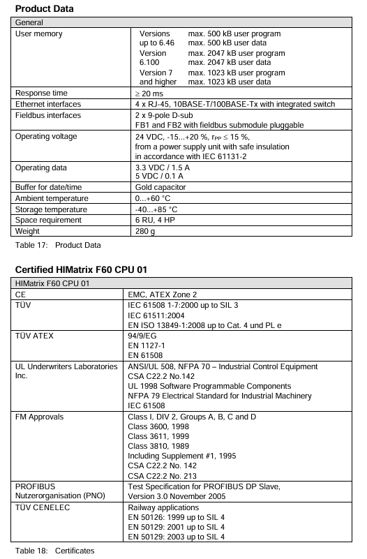
Storage configuration CPU OS ≤ V6. x: maximum 500kB user program, 500kB user data;
CPU OS ≥ V7: maximum 2047 KB user program, 2047 KB user data;
Date/Time Cache: Powered by Gold Capacitor
Indicator light system LED (RUN/ERR), program LED (STOP/PROG/FAULT/ORCE/OSL/BL), communication LED (Ethernet/fieldbus)
Mechanical characteristic dimensions: 6 RU (rack unit), 4 HP; weight: 280g; protection level: IP20
2. Power and environmental requirements
Power supply parameters: rated voltage 24VDC, allowable fluctuation range -15%~+20% (18~28.8VDC), ripple peak ≤ 15%; Working current: 3.3VDC/1.5A, 5VDC/0.1A.
Environmental restrictions: working temperature of 0-60 ℃, storage temperature of -40~85 ℃, pollution level II (IEC/EN 61131-2), altitude ≤ 2000m, no condensation.
Voltage monitoring: Built in voltage monitoring function, triggering an alarm (written to system variables) when<18VDC, and automatically shutting down when<13VDC.
3. Communication Protocol and Ports
(1) Support agreement
Safety related: Safe Ethernet.
Standard protocols: Modbus TCP, OPC, SNTP (time synchronization) TCP S/R; Ethernet/IP only supports CPU OS ≤ V6. x.
(2) Default network port
Port Type Port Number Purpose
UDP 8000 Programming Tool (PADT) Connection
UDP 8001 ELOP II Factory Remote I/O Configuration
UDP 8004 SILworX Remote I/O Configuration
UDP 6010 Secure Ethernet OPC
UDP 123 SNTP time synchronization
UDP/TCP 502 Modbus (user modifiable)
TCP 44818 EtherNet/IP Explicit Messaging Service
TCP 2222 EtherNet/IP data exchange
Safety operation standards
1. Electrostatic protection (ESD)
Operators must master ESD protection knowledge, wear anti-static wristbands during work, and ensure that the work area is free of static electricity interference.
When the module is idle or transported, it should be stored in the original factory anti-static packaging and direct contact with the circuit board is prohibited.
2. Installation and operation safety
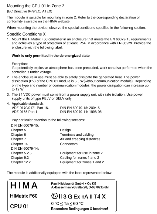
Installation restrictions: Zone 2 scenarios must be placed in an enclosure with a protection level of IP54 or higher, and the enclosure must be labeled with "Only power-off operation allowed (except when explosion risk is excluded)".
Cable requirements: Signal lines and power lines should be wired separately to avoid interference; Zone 2 installation must comply with DIN EN 60079-15/14 standards (terminals, wiring, creepage distance, etc.).
Prohibited behavior: live plugging and unplugging modules or cables; Operate the reset button during module operation; Replace core components with non original parts.
3. Emergency and residual risks
Emergency response: When the module fails, it automatically enters a safe state (input processing stops, output power is cut off), and any operation that prevents the safe operation of the system is prohibited.
Residual risks: may arise from engineering design defects, user program errors, wiring faults, and need to be avoided through compliant design and regular testing.
Installation and configuration process
1. Installation steps
(1) Basic installation (inside the rack)
In the power-off state, insert the module along the upper and lower rails of the rack, align it with the backplane slot, and press the front end board until the buckle "clicks" to lock.
Secure the module with screws on both sides of the front panel to ensure a secure installation.
Connection cables: Ethernet cable (RJ-45), fieldbus cable (D-sub, requiring sub module connection), power cord (powered by power module, no direct wiring required).
(2) Zone 2 Special Installation
Additional requirements: The enclosure protection level should be ≥ IP54 to ensure heat dissipation (the basic power consumption of the module is 6.5W, and it can reach 12W when equipped with a communication submodule).
Power requirements: PELV/SILV grade safety isolation power supply must be used, in compliance with IEC 61131-2 standard.
Label pasting: The shell needs to be pasted with ATEX compliant labels, and the module comes with an "Ex113GExnA II T4X" label.
2. Configuration process
(1) Tool selection and preliminary preparation
Confirm module OS version: Select the corresponding programming tool (ELOP II Factory/SILworX) based on the model label or front-end LED.
Reference documents: HIMatrix system manual (HI 800 191 E), safety manual (HI 800 023 E), and programming tool help documentation are required.
(2) Core configuration steps
Hardware Mapping: Create a project in the programming tool and configure the CPU module (Slot 2) and I/O module (Slot 3~8) according to the rack slot. There is a slight difference in slot numbers between SILworX and ELOP II Factory (refer to the table below). |Rack slot | SILworX slot number | ELOP II Factory slot number | Module type | | --- | --- | --- | --- | | | | | | 1 | - | PS 01 power module (no configuration required) | | 2 | 0 (CPU)/1 (COM) | - | CPU/communication module (integrated) | | | 3 | 2 | 1 | I/O module | | 4 | 3 | 2 | I/O module | | | 5~8 | 4~7 | 3~6 | I/O module|
Network configuration: Set the IP address (default 192.168.0.99) and subnet mask to ensure consistency with the PADT (programming computer) network segment; If modifications are required, they can be restored to default values through programming tools or reset functions.
Programming and downloading: Write user programs using IEC 61131-3 standard languages such as Function Block Diagram (FBD), compile them, and download them to the module Flash EPROM.
Security configuration: Set the watchdog time (WDT) and security cycle time according to the security manual, and configure security communication parameters (if applicable).
3. Reset operation (restore default settings)
Applicable scenario: Forgetting administrator account password or IP address conflicts with PADT.
Operation steps:
Disconnect the module power supply and unplug all fieldbus connectors (to avoid interfering with other devices).
Insert a needle shaped insulating material into the reset hole of the front end board, press and hold for ≥ 20 seconds, and at the same time, turn on the power to restart the module.
Reset effect: The IP address is restored to 192.168.0.99, the system ID (SRS) is restored to 6000.0.0, and only the default administrator account (empty password) is activated.
Note: In COM OS versions ≥ 10.42, after resetting, it is necessary to reconfigure the connection parameters and account before downloading the program/OS.
Operation and Diagnosis
1. Running status indication (LED interpretation)
The LED status of the module varies slightly with the CPU OS version, and its core meaning is as follows:
(1) System LED
Meaning of LED color status (CPU OS ≥ V8)
RUN green constantly on and running normally (STOP/RUN status)
RUN green Blinking1 (600ms on/off) is loading a new operating system
RUN green off, non RUN state
ERR red constant light lacks additional function authorization and testing mode
ERR red Blinking1 fault shutdown (hardware/voltage/configuration failure), requiring PADT restart
ERR red goes out without any malfunction
(2) Program LED
STOP (red): Always on=STOP/valid configuration; Blinking=STOP/Invalid configuration.
PROG (yellow): Always on=loading configuration/OS, modifying WDT/safe time/SRS.
Fault (yellow): Blinking=OS damage, invalid configuration, I/O failure.
FORCE (yellow): constantly on=forced function preparation; Flashing=forced function activation.
(3) Communication LED
Ethernet (next to RJ-45): Green=Full Duplex; Yellow=connection is valid; Flashing=data transmission/conflict.
Fieldbus (FB1/FB2): yellow=interface activated; Synchronized flashing=emergency loader activated.
2. Basic operating procedures
(1) Start the process
Confirm that the module is securely installed, the cable connections are correct, and there is no risk of static electricity.
Connect the power module to supply power, and the module will automatically perform LED self-test (all LEDs will briefly light up).
Start the programming tool and establish a communication connection with the module (via IP address).
Download user programs and configuration files to verify the validity of the configuration.
Switch the module to RUN state and confirm normal operation through LED and programming tools.
(2) Shutdown process
Normal shutdown: Use programming tools to switch the module to STOP state, and disconnect the power after the program stops.
Emergency stop: When the module fails, it automatically enters the ERROR STOP state, and after troubleshooting, it restarts through PADT.
3. Diagnostic methods
First level diagnosis: Determine the fault type based on the status of the front-end LED (such as ERR flashing=system fault, FAULT flashing=I/O fault).
Secondary diagnosis: By using programming tools to read diagnostic logs and system variables (such as power status and temperature status), locate specific fault points.
Common diagnostic items: communication failure (port/protocol configuration), invalid configuration (slot mapping error), hardware failure (voltage/module damage).
Maintenance and troubleshooting
1. Daily maintenance
Regular maintenance: Conduct a Proof Test every 10 years, refer to the HIMatrix Safety Manual (HI 800 023 E).
System update: Use downtime to upgrade the operating system through programming tools (first place the module in STOP state), and confirm the compatibility of the new version before upgrading.
Cleaning requirements: Wipe the outer shell with a dry soft cloth, and do not clean with water or chemical solvents; Regularly check that the cooling vents are unobstructed.
2. Fault handling
(1) Common faults and solutions
Possible causes and solutions for the fault phenomenon
The module cannot be started, ERR is constantly on and the voltage is too low. Check the power supply voltage (≥ 18VDC) for hardware faults and replace the module
Communication failure, Ethernet LED off, IP address conflict, cable damage investigation, IP conflict (communication LED synchronously flashing=conflict), replace network cable
Program cannot be downloaded, invalid PROG flashing configuration, incompatible OS version, verification slot mapping and configuration parameters, upgrading/downgrading OS
I/O unresponsive, FAULT flashing. I/O module fault, wiring error. Check the I/O module connection, rewire and test
There is no communication on the fieldbus, and the FB LED is off. The fieldbus submodule has not been installed, and a compatible fieldbus submodule has been installed
(2) Module replacement process
Disconnect the power supply module and unplug all connecting cables (Ethernet, fieldbus).
Loosen the module fixing screws and remove the module from the rack rail through the bottom handle.
Fix the new module according to the installation steps, connect the cables, and ensure that the wiring is consistent with the original module.
Connect the power, download the original configuration and program, and verify that it runs normally.
Attention: Only modules of the same model or HIMA authorized substitute models can be replaced, and mixing different variants (CPU 01/CPU 01 SILworX) is prohibited.
- YOKOGAWA
- Reliance
- ADVANCED
- SEW
- ProSoft
- WATLOW
- Kongsberg
- FANUC
- VSD
- DCS
- PLC
- man-machine
- Covid-19
- Energy and Gender
- Energy Access
- Renewable Integration
- Energy Subsidies
- Energy and Water
- Net zero emission
- Energy Security
- Critical Minerals
- A-B
- petroleum
- Mine scale
- Sewage treatment
- cement
- architecture
- Industrial information
- New energy
- Automobile market
- electricity
- Construction site
- HIMA
- ABB
- Rockwell
- Schneider Modicon
- Siemens
- xYCOM
- Yaskawa
- Woodward
- BOSCH Rexroth
- MOOG
- General Electric
- American NI
- Rolls-Royce
- CTI
- Honeywell
- EMERSON
- MAN
- GE
- TRICONEX
- Control Wave
- ALSTOM
- AMAT
- STUDER
- KONGSBERG
- MOTOROLA
- DANAHER MOTION
- Bentley
- Galil
- EATON
- MOLEX
- Triconex
- DEIF
- B&W
- ZYGO
- Aerotech
- DANFOSS
- KOLLMORGEN
- Beijer
- Endress+Hauser
- schneider
- Foxboro
- KB
- REXROTH
- YAMAHA
- Johnson
- Westinghouse
- WAGO
- TOSHIBA
- TEKTRONIX
- BENDER
- BMCM
- SMC
- HITACHI
- HIRSCHMANN
- XP POWER
- Baldor
- Meggitt
- SHINKAWA
- Other Brands
- UniOP
- KUKA
- IBA
- Beckhoff
-
ADLINK PCI-8134 - 51-12403-0B20 PCB Board Motion Controller Card
-
ADLINK LPCI-3488A - PCI Card 51-12801-0A30 Low Profile IEEE-488 GPIB Card
-
ADLINK NUPRO-900A - industrial computer motherboard Single Board Computer
-
ADLINK cPCI-6840V - industrial control motherboard CompactPCI SBC
-
ADLINK M-342 - industrial motherboard ATX Mainboard
-
ADLINK NUPRO-935A/LV - industrial control motherboard
-
ADLINK cPCI-3538 - CompactPCI Async Serial Communications Module
-
ADLINK PCI-1610 - Card 4-Port RS-232 PCI Serial Communication Card
-
ADLINK HSL-DI32-DB-N - Distributed I/O Module 32-CH Digital Input
-
ADLINK CPCI-6860A - motherboard E7501 CompactPCI Single Board Computer
-
ADLINK PCI-8134A - 4-Axis Motion Control Card PCB Board
-
ADLINK EURESYS LINK - grabbers Video Capture Card Frame Grabber
-
ADLINK NuPRO-965DV - motherboard Industrial Control Board
-
Thermo Fisher Scientific 80100-60500 - 80000-61010R 80000-21000R 80000-60457 Spectrum System Controller ADLINK Components
-
ADLINK PCI-7296 - IO card High Density 96-CH Opto-Isolated DIO Card
-
ADLINK MXC-6322D - Matrix Industrial Computer Fanless Embedded PC
-
ADLINK DIN-825-GP4 - connector board Terminal Block Interface
-
ADLINK AMP-208C - Motion Control Card DSP-based 8-axis
-
ADLINK PCIe-GIE72 - 51-18531-0A10 2-CH GigE Vision Frame Grabber PoE+ Card
-
ADLINK PXIS-3320 - PXI/PXIe Chassis 15-slot 6U PXI/CompactPCI SEM-I-1518=9N41
-
ADLINK MI-965 - Industrial CPU Motherboard
-
ADLINK M-302 - Industrial control motherboard
-
ADLINK PCI-6308V - 51-12202-0A50 Isolated Analog Output Card PCB-I-E-1813=ZA03
-
ADLINK NUPRO-935A - Industrial Mother Board CPU Board
-
ADLINK PCI-7434 - PLOTECH Digital Output Card PCB-I-E-1182=6EX2
-
ADLINK PCI-7432 - 64 Channel Isolated Digital I/O PCI CARD
-
ADLINK NUPRO-935A/DV - 51-41802-0A10 motherboard Industrial Control Board
-
ADLINK PCIe-GIE72 - 51-18531-0A10 2-CH GigE Vision Frame Grabber PoE+ Card
-
ADLINK HSL-DI16DO16-M-NN - HSL-DI16DO16-M-NN(G)-0280 Discrete I/O Module Distributed I/O
-
ADLINK cPCI-6760D / cPCI-6840V - cPCI Single Board Computer Industrial Motherboard
-
ADLINK NuPRO-A301 - Motherboard IPC Motherboard
-
ADLINK NuPRO-935A/LV - motherboard Industrial Control Board
-
ADLINK NUPRO-E320LV - motherboard Industrial Control Board
-
ADLINK NuPRO-E42 - Industrial Control Board Motherboard
-
ADLINK M-342 - ATX Motherboard Industrial PC Mainboard
-
ADLINK CPCI-6860 / 6860A - Industrial Control Motherboard CompactPCI SBC
-
ADLINK AmITX-SL-G-Q170/GEHC(EA)-021E - 51-7A104-0A20 Industrial Motherboard w/ DDR4
-
ADLINK NUPRO-852 / NUPRO-852LV - industrial control motherboard
-
ADLINK DAQ-2006-004 - Multi-Function DAQ Cards Data Acquisition
-
ADLINK PCIe-RTV24 - Frame Grabbers Video Capture Cards PCI-e x1 4-CH 120fps
-
ADLINK PCI-8134 - 51-12403-0B20 4-Axis Motion Controller Card
-
ADLINK PCI-8132 - 2-Axis Motion Controller Card
-
ADLINK cBP-6402 - Backplane Passive Backplane
-
ADLINK cPCI-6760D - cPCI Single Board Computer Industrial Control Motherboard
-
ADLINK DIN-825-4PO(G)-0030 - Terminal Board Motion Control Breakout Board
-
ADLINK M-322 - Industrial Motherboard
-
ADLINK ABX-1301 - 51-63808-0A20 Industrial Motherboard
-
ADLINK PCI-7433 - 64-CH Isolated Digital Input Card
-
ADLINK AMP-208C - Motion Control card
-
ADLINK DIN-50S-01 - TECHNOLOGY TERMINAL BLOCK INTERFACE MODULES W/ DIN RAIL
-
ADLINK PCI-8134 - 51-12403-0B20 4-Axis Motion Controller Card
-
ADLINK MXE-201/MSSD64G - Technology Automation Computer Fanless Embedded System
-
ADLINK USB-3488A (G) - USB to GPIB CARD Controller Interface
-
ADLINK cPCI-3720L2 - SBC Single Board Computer PCB AMAT 0190-14599
-
ADLINK PCI-7251 - Relay Output Board Expansion Module
-
ADLINK PCI-8124-C - PCB Board 4-CH Encoder Trigger Card
-
ADLINK HD636 - Industrial Computer Board PCB-I-E-2200=9L32-2 Main Board
-
ADLINK USB-3488A - THERMOTRON INDUSTRIES IEEE 488 CPU INTERFACE WITH USB/GPIB
-
ADLINK MI-965 - motherboard Industrial CPU Board
-
ADLINK LPCIe-7250 - Technology Digital IO card Low Profile PCIe Relay Output
-
ADLINK NuPro-720/SCOPUS - Technology With 256MB Industrial MotherBoard
-
ADLINK NuPR0-840 - industrial control motherboard
-
ADLINK M-342 - Motherboard ATX PC Mainboard
-
ADLINK MI-965 - motherboard Industrial CPU Board
-
ADLINK CPCI-6530V/4402E/M4G - AMAT CPCI-6503VED/4402E/M4-0/SD64G-2550 Universal SBC
-
ADLINK IMB-M43-IRV - Industrial Motherboard ATX PC Board
-
ADLINK 52983 / 58183 - Chroma PXI I/O Input/Output Card + Carrier Adapter
-
ADLINK PXI-3920 - PXI 3U cPCI Industrial Controller w/ RAM SSD Embedded CPU
-
ADLINK NuPRO-842LV/P - motherboard Industrial Control PC Board
-
ADLINK PCI-7442 - 64-Channel Datalogging Acquisition Switch Card
-
ADLINK PCIe-RTV24 - Cadre Agrippeurs Vidéo de Capture Cartes Pci-E x1 4-CH
-
ADLINK ACL-7122A - TECHNOLOGY 51-11004-1A1 CIRCUIT BOARD 96-CH DIO Card
-
ADLINK PCIe-RTV24 - 51-18016-0A20 Image Acquisition Video Capture Card
-
ADLINK AMP-204C - DSP-Based 4-Axis Advanced Pulse-Train Motion Controller
-
ADLINK 52981 / 58183 - Chroma PXI Digital I/O DIO Input/Output Card + Carrier Adapter
-
ADLINK PCI-8102 - motion control card 2-Axis
-
ADLINK NuPRO-E320LV - industrial computer motherboard
-
ADLINK PCI-RTV24 - card Analog Video Capture Frame Grabber
-
ADLINK M-302 - Motherboard P/N: 08GSAQ96501102
-
ADLINK NEON-1020 - Smart camera Industrial Machine Vision
-
ADLINK AMP- 208C - card DSP-based 8-axis Motion Controller
-
ADLINK PCI-9114DG - Multi-Function Daq Card Data Acquisition
-
ADLINK MXC-6322D/BE_FanG) - Matrix PM2-MXC Fanless Embedded Computer
-
ADLINK DIN-825-4P0 - Terminal Board Motion Control Breakout Board
-
ADLINK HPCI-8S4 REV.B2 - Industrial Control Base Plate Passive Backplane
-
ADLINK HSL-DI32-DB-N - Distributed I/O Module 32-CH Digital Input
-
ADLINK NuPRO-935A/DV - industrial control motherboard
-
ADLINK PCI-7442 - Switch card 64-CH Datalogging Acquisition Card
-
ADLINK NuPRO-E42 - motherboard 51-41808-0A30 Industrial Motherboard
-
ADLINK CPCI-3610D/N45/M1G(G)-10B0 - CompactPCI Intel Atom Single Board Computer CPU Board
-
ADLINK LPCI-7250 - GP Output Isolated Digital Input Card PCB 51-12803-0A10
-
ADLINK PCI-7250 - 51-12007-0A40 PCI7250 8-CH Relay Output & 8-CH Isolated DI Card
-
ADLINK STC-1005 - 10.4inch touch panel PC E3845 CPU
-
ADLINK PCI-FIW64 - image card FireWire Frame Grabber
-
ADLINK NuPRO-935A/LV - industrial computer motherboard
-
ADLINK PCI-8164 00B0 - Centralized Motion Controller 4-axis PCB-I-E-1179=6EX2
-
ADLINK ACLD-9137F REV A1 - 51-14006-101 Screw Termination Board
-
ADLINK PCI-7248 - 51-12006-0A40 Control Card Digital I/O
-
ADLINK HPCI-8S4 - Technology Backplane PCB GaSonics 3500 Asher Passive Backplane
-
ADLINK NuPRO-E320LV - Cpu Board 51-41804-0A20 Industrial Motherboard
-
ADLINK HPX-13S4 - device baseboard Passive Backplane
-
ADLINK M-322 - industrial motherboard
-
ADLINK NuPRO-865 REV :3.0 - industrial motherboard
-
ADLINK DIN-68S-01 - Terminal Block Interface Module Cable Connection
-
ADLINK ETX-IM266-C100Z - motherboard ETX CPU Module
-
ADLINK NuPRO-E320LV - motherboard Industrial Control Board
-
ADLINK NuPRO-841 REV:2.0 - motherboard Industrial PC Board
-
ADLINK ETX-AT-N270-18 - N270 Board ASH-EAT-18/S512 ET Mainboard
-
ADLINK PCI-RTV24 - Image capture card Analog Frame Grabber
-
ADLINK PCI-8102 - card 2-Axis Motion Controller
-
ADLINK M-322 - industrial motherboard
-
ADLINK PCI-9114 REV.C2 - acquisition card Multi-Function DAQ
-
ADLINK NuPRO-865 REV :3.0 - industrial motherboard
-
ADLINK DIN-68S-01 - Terminal Block Interface Module Cable Connection
-
ADLINK M-322 - Industrial Motherboard Mainboard
-
ADLINK CPCI-6860A - E7501 dual Xeon CPCI Single Board Computer
-
ADLINK MXC-6301D(G) - Technology Expandable Fanless Embedded Computer i7-3610E
-
ADLINK NuPRO-842LV - 51-41360-0B1 Industrial Motherboard
-
ADLINK PBP-08A7 R1MO - PCB Industrial Computer Backplane Passive Backplane
-
ADLINK PCI-3488 - PCI BOARD IEEE-488 GPIB Controller Card
-
ADLINK NuPRO-935A/LV - Industrial Control Motherboard
-
ADLINK PCI-8134 - TECH 4-AXIS MOTION CONTROLLER 4209NB2039 AT23A
-
ADLINK Karbon 700-X2 - Expanded High-Performance Rugged Edge Computer Windows 10
-
ADLINK PCIe-9852 - ADcard 2-CH 8-Bit 200MS/s Digitizer Card
-
ADLINK ETX-BT-E3815 - Industrial Control Module NO AUDIO 91-71116-E020 CT66
-
ADLINK cPCI-8168-006 - cPCI NulPC Motion Control Board
-
ADLINK NuPRO-E43 - 51-41809-0A30 industrial motherboard
-
ADLINK PCI-8134A - PCB Board Motion Controller Card

K-JIANG

Add: Jimei North Road, Jimei District, Xiamen, Fujian, China
Tell:+86-15305925923