
K-WANG


Westinghouse WPX3000e/WPX3400e electric high-pressure cleaning machine
Westinghouse WPX3000e/WPX3400e electric high-pressure cleaning machine
Overview
The comprehensive guidance document for the Westinghouse WPX3000e (3000 PSI maximum pressure/1.76 GPM maximum flow) and WPX3400e (3400 PSI maximum pressure/2.0 GPM maximum flow) electric high-pressure cleaning machines covers product safety specifications (such as prohibiting direct spraying of human/electrical objects, anti electric shock/anti freezing measures), detailed parameters, assembly steps (including installation of wheels, handles and other components), operating procedures (preparation before start-up, power on/off, nozzle selection and use), maintenance (cleaning, storage, replacement of vulnerable parts) and troubleshooting, while emphasizing the need for product registration to protect warranty rights.
Core parameters and configuration of the product
1. Comparison Table of Model Parameters
Parameter category WPX3000e WPX3400e
Water temperature requirement: Cold Water Only
Maximum pressure (PSI) 3000 3400
Rated pressure (PSI) 2600 3000
Maximum Flow Rate (GPM) 1.76 (6.7 LPM) 2.0 (7.57 LPM)
Rated flow rate (GPM) 1.1 (4.16 LPM) 1.1 (4.16 LPM)
Power parameters 120V AC/60Hz/13A 120V AC/60Hz/14A
Core protection double insulation structure, GFCI leakage protection double insulation structure, GFCI leakage protection
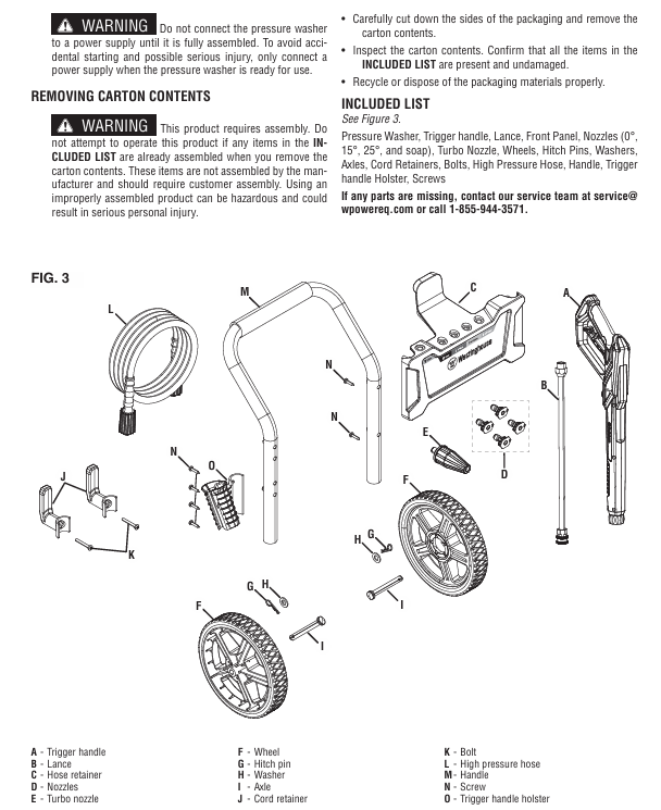
2. Standard accessory list
Main components: high-pressure cleaning machine body, spray gun handle, spray long gun, front panel
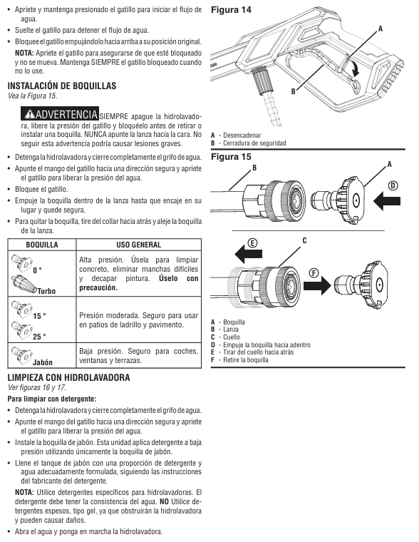
Nozzle group: 0 ° turbine nozzle (high pressure), 15 ° nozzle (medium pressure), 25 ° nozzle (medium pressure), soap nozzle (low pressure)
Auxiliary accessories: 2 wheels, axle pins, washers, wire clamps, high-pressure hoses, handles, nozzle storage racks, screws/bolts
Safety Operation Standards (Key)
1. Environment and usage restrictions
Prohibited scenarios: indoor/enclosed spaces (carbon monoxide free, this is electric, mainly to prevent electric shock), rainy/snowy/damp floors, near electrical appliances/combustibles (≥ 6 feet distance), using hot water (only cold water, hot water will damage pump seals).
Water source requirements: Only tap water is allowed, and the use of lake water, pool water, and swimming pool water (which can clog the filter) is prohibited. The inlet pressure should be ≤ 150 PSI.
2. Electrical safety
GFCI protection: The plug has built-in GFCI and needs to be tested monthly (press the TEST button to hear a "click" sound, then press RESET to reset). To replace the plug/wire, accessories with GFCI of the same specifications are required.
Extension cable restrictions (not recommended, use only when absolutely necessary):
WPX3000e: wire diameter ≥ 16 AWG, length ≤ 50 feet;
WPX3400e: wire diameter ≥ 14 AWG, length ≤ 25 feet;
Do not use damaged extension cords to avoid voltage drop causing motor overheating.
3. Operation taboos
It is prohibited to directly spray human bodies, animals, glass, and electrical appliances (which are prone to injury/damage/electric shock);
The pump body should not idle for more than 1 minute (after cutting off water), otherwise the motor/pump will overheat and be damaged;
Before disassembling the nozzle, it is necessary to stop the machine, release pressure (press the spray gun to release pressure), and lock the trigger;
Children are not allowed to operate it, and adults should avoid using it under the influence of alcohol/drugs.
Assembly steps
1. Key assembly process (tools required: screwdriver, wrench)
Wheel installation: Place the body on the side, pass the shaft through the wheel and washer → insert into the body bracket → fix with the shaft pin;
Install the handle: slide the handle into the slot of the body, press the buckle until it makes a "click" sound to ensure stability;
Wire clamp and nozzle holder: Align the holes of the wire clamp/nozzle holder and fix them on the side of the machine with screws;
Connect the spray gun and hose: One end of the high-pressure hose is connected to the threaded interface of the machine body (tighten the locking nut), and the other end is connected to the spray gun (insert after pulling the collar and tighten the locking nut).
Complete operational process
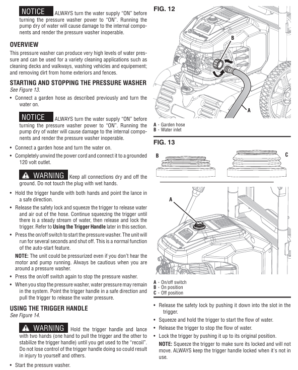
1. Preparation before startup
Water source connection: Connect the garden hose to the machine's water inlet. First, rinse the hose for a few seconds to remove impurities and check the inlet filter screen (no damage/blockage);
Oil/Consumables: For the new machine, add 10W30 4-stroke engine oil (to the H-L range of the dipstick), and add a special high-pressure cleaning machine to the soap tank using a remover (dilute according to the instructions, do not use detergent/laundry detergent, as it may clog the nozzle);
Load check: Disconnect all nozzles, ensure trigger lock, and reset circuit breaker.
2. Startup and operation
Step operation details
1. Open the water source, press the trigger of the spray gun to release air until the water flow is stable (without bubbles), and then lock the trigger
Plug in the GFCI plug and press the power switch to "ON". The device will run for 1-2 seconds before shutting down (automatic start stop function, normal)
3 nozzle options: Install nozzle after shutdown and pressure relief (0 ° turbine for paint removal/concrete washing, 15 °/25 ° brick and stone washing, soap spray detergent)
Unlock the trigger, hold the gun with both hands (anti recoil), aim at the cleaning face, press the trigger to start spraying, and move from bottom to top to clean
3. Shutdown and Storage
Normal shutdown: Disconnect the nozzle → Run without load for 3-5 minutes to cool down → Press the power switch to "OFF" → Unplug the plug → Drain the water from the hose/pump;
Long term storage (over 30 days): Empty soap tank and rinse with clean water → Change engine oil → Remove spark plug and add 1 tablespoon of engine oil (lubricate cylinder) → Store in a dry and constant temperature place (anti icing/overheating, optional pump protector).
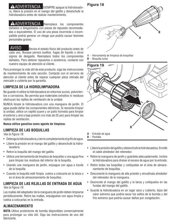
Maintenance and upkeep
1. Maintenance cycle and content table
Maintenance project maintenance frequency operation details
Before each use, remove the inlet filter and rinse it with clean water. If there is no damage, reinstall it
Spray nozzle cleaning every 50 hours/when clogged, use a nozzle cleaning tool/fine needle to pass through the nozzle hole and rinse with clean water in reverse
Clean the body with a soft cloth after each use, blow the vents with low-pressure air (≤ 25 PSI), and prohibit water flushing of electrical components
Lubricate the O-ring of the hose and clean it every 100 hours before applying Vaseline (non water soluble grease)
Replacement of vulnerable parts every 300 hours/replacement of nozzle, inlet filter screen, hose O-ring when damaged, recommended original accessories (such as turbine nozzle PWTN, filter screen 04000267-0)
2. Precautions
Waste engine oil/detergent cannot be dumped and must be disposed of according to EPA regulations;
Do not use flammable solvents such as gasoline to clean components and avoid corrosion;
Before maintenance, the power must be cut off, the pressure must be relieved, and the standby body must be cooled to room temperature.
Troubleshooting
Common troubleshooting solutions table
Possible causes and solutions for the fault phenomenon
The body is not powered on. 1. It is not grounded to a power source; 2. GFCI trips; 3. Damaged power cord. 1. Connect to a 120V grounded socket; 2. Press the GFCI reset button; 3. Contact after-sales service to replace the power cord
Running without water flow: 1. Wrong water source (not tap water); 2. nozzle blockage; 3. Spray gun malfunction 1. Replace with tap water; 2. Clean the nozzle; 3. Replace the spray gun
The connection between the hose and the spray gun is leaking, and the O-ring is missing/damaged. After stopping the machine and releasing pressure, replace the O-ring with the same specification
Stop the machine after 2 seconds of startup, unable to restart the automatic start stop function (pump pre pressure). Press the spray gun trigger to release pressure, and the machine will automatically start (normal phenomenon, not a fault)
Key questions and answers
Question 1: What are the differences in the use of extension cords between WPX3000e and WPX3400e? Why is there such a restriction?
Answer: The difference lies in the different specifications of the extension cord - WPX3000e requires the use of extension cords with a wire diameter of ≥ 16 AWG (American Wire Gauge) and a length of ≤ 50 feet; WPX3400e requires the use of extension cords with a wire diameter of ≥ 14 AWG and a length of ≤ 25 feet. The reason is that the rated current of the two models is different (WPX3000e is 13A, WPX3400e is 14A). The thinner and longer the wire diameter, the greater the resistance, which can easily lead to voltage drop, resulting in a decrease in motor power and overheating damage; WPX3400e has a higher current, so a thicker wire diameter and shorter length are required to reduce losses.
Question 2: What are the applicable scenarios for different nozzles when using a high-pressure cleaning machine? What are the consequences of making a wrong choice?
Answer: Different nozzles are suitable for the following scenarios:
0 ° Turbine Nozzle: High pressure mode, suitable for cleaning concrete, removing stubborn stains, and peeling paint (requires close range use, strong force);
15 °/25 ° nozzle: medium pressure mode, suitable for cleaning masonry tiles, exterior walls, and vehicles (moderate force to avoid scratches);
Soap nozzle: Low pressure mode, only used for spraying detergent (unable to suck soap under high pressure and easily causing detergent splashing and waste).
The consequences of choosing the wrong option: Cleaning the vehicle/wood with a 0 ° nozzle can cause surface scratches; The efficiency of using a medium pressure nozzle to treat stubborn stains is extremely low; Spraying Detergent in high-pressure mode can cause blockage of the soap circuit and even damage to the soap tank.
Question 3: What are the key steps to complete before storing a high-pressure cleaning machine for a long time? What is the purpose?
Answer: Long term storage (over 30 days) requires completing 5 key steps, with the following objectives and details:
Empty and rinse soap tank: Start the machine with clean water and spray it out with soap nozzle to prevent residual detergent from solidifying and blocking the soap path;
Change engine oil: Drain the old oil and add new 10W30 oil to prevent impurities in the old oil from corroding the crankcase components;
Lubricate the cylinder: Remove the spark plug, inject 1 tablespoon of engine oil, and pull the recoil handle several times to form an oil film on the cylinder wall and prevent long-term storage rust;
Drain water: Disconnect the water source and use the spray gun to drain the water from the hose/pump. The purpose is to prevent water from freezing and expanding in low-temperature environments, which may cause the pump body/hose to crack;
Constant temperature and dry storage: stored at ≥ 0 ℃ in a dry and ventilated place, with the purpose of preventing electrical components from being affected by moisture and short circuiting, as well as avoiding aging of pump seals caused by high temperatures.
- YOKOGAWA
- Reliance
- ADVANCED
- SEW
- ProSoft
- WATLOW
- Kongsberg
- FANUC
- VSD
- DCS
- PLC
- man-machine
- Covid-19
- Energy and Gender
- Energy Access
- Renewable Integration
- Energy Subsidies
- Energy and Water
- Net zero emission
- Energy Security
- Critical Minerals
- A-B
- petroleum
- Mine scale
- Sewage treatment
- cement
- architecture
- Industrial information
- New energy
- Automobile market
- electricity
- Construction site
- HIMA
- ABB
- Rockwell
- Schneider Modicon
- Siemens
- xYCOM
- Yaskawa
- Woodward
- BOSCH Rexroth
- MOOG
- General Electric
- American NI
- Rolls-Royce
- CTI
- Honeywell
- EMERSON
- MAN
- GE
- TRICONEX
- Control Wave
- ALSTOM
- AMAT
- STUDER
- KONGSBERG
- MOTOROLA
- DANAHER MOTION
- Bentley
- Galil
- EATON
- MOLEX
- Triconex
- DEIF
- B&W
- ZYGO
- Aerotech
- DANFOSS
- KOLLMORGEN
- Beijer
- Endress+Hauser
- schneider
- Foxboro
- KB
- REXROTH
- YAMAHA
- Johnson
- Westinghouse
- WAGO
- TOSHIBA
- TEKTRONIX
- BENDER
- BMCM
- SMC
- HITACHI
- HIRSCHMANN
- XP POWER
- Baldor
- Meggitt
- SHINKAWA
- Other Brands
- UniOP
- KUKA
- IBA
- Beckhoff
-
ADLINK PCI-8134 - 51-12403-0B20 PCB Board Motion Controller Card
-
ADLINK LPCI-3488A - PCI Card 51-12801-0A30 Low Profile IEEE-488 GPIB Card
-
ADLINK NUPRO-900A - industrial computer motherboard Single Board Computer
-
ADLINK cPCI-6840V - industrial control motherboard CompactPCI SBC
-
ADLINK M-342 - industrial motherboard ATX Mainboard
-
ADLINK NUPRO-935A/LV - industrial control motherboard
-
ADLINK cPCI-3538 - CompactPCI Async Serial Communications Module
-
ADLINK PCI-1610 - Card 4-Port RS-232 PCI Serial Communication Card
-
ADLINK HSL-DI32-DB-N - Distributed I/O Module 32-CH Digital Input
-
ADLINK CPCI-6860A - motherboard E7501 CompactPCI Single Board Computer
-
ADLINK PCI-8134A - 4-Axis Motion Control Card PCB Board
-
ADLINK EURESYS LINK - grabbers Video Capture Card Frame Grabber
-
ADLINK NuPRO-965DV - motherboard Industrial Control Board
-
Thermo Fisher Scientific 80100-60500 - 80000-61010R 80000-21000R 80000-60457 Spectrum System Controller ADLINK Components
-
ADLINK PCI-7296 - IO card High Density 96-CH Opto-Isolated DIO Card
-
ADLINK MXC-6322D - Matrix Industrial Computer Fanless Embedded PC
-
ADLINK DIN-825-GP4 - connector board Terminal Block Interface
-
ADLINK AMP-208C - Motion Control Card DSP-based 8-axis
-
ADLINK PCIe-GIE72 - 51-18531-0A10 2-CH GigE Vision Frame Grabber PoE+ Card
-
ADLINK PXIS-3320 - PXI/PXIe Chassis 15-slot 6U PXI/CompactPCI SEM-I-1518=9N41
-
ADLINK MI-965 - Industrial CPU Motherboard
-
ADLINK M-302 - Industrial control motherboard
-
ADLINK PCI-6308V - 51-12202-0A50 Isolated Analog Output Card PCB-I-E-1813=ZA03
-
ADLINK NUPRO-935A - Industrial Mother Board CPU Board
-
ADLINK PCI-7434 - PLOTECH Digital Output Card PCB-I-E-1182=6EX2
-
ADLINK PCI-7432 - 64 Channel Isolated Digital I/O PCI CARD
-
ADLINK NUPRO-935A/DV - 51-41802-0A10 motherboard Industrial Control Board
-
ADLINK PCIe-GIE72 - 51-18531-0A10 2-CH GigE Vision Frame Grabber PoE+ Card
-
ADLINK HSL-DI16DO16-M-NN - HSL-DI16DO16-M-NN(G)-0280 Discrete I/O Module Distributed I/O
-
ADLINK cPCI-6760D / cPCI-6840V - cPCI Single Board Computer Industrial Motherboard
-
ADLINK NuPRO-A301 - Motherboard IPC Motherboard
-
ADLINK NuPRO-935A/LV - motherboard Industrial Control Board
-
ADLINK NUPRO-E320LV - motherboard Industrial Control Board
-
ADLINK NuPRO-E42 - Industrial Control Board Motherboard
-
ADLINK M-342 - ATX Motherboard Industrial PC Mainboard
-
ADLINK CPCI-6860 / 6860A - Industrial Control Motherboard CompactPCI SBC
-
ADLINK AmITX-SL-G-Q170/GEHC(EA)-021E - 51-7A104-0A20 Industrial Motherboard w/ DDR4
-
ADLINK NUPRO-852 / NUPRO-852LV - industrial control motherboard
-
ADLINK DAQ-2006-004 - Multi-Function DAQ Cards Data Acquisition
-
ADLINK PCIe-RTV24 - Frame Grabbers Video Capture Cards PCI-e x1 4-CH 120fps
-
ADLINK PCI-8134 - 51-12403-0B20 4-Axis Motion Controller Card
-
ADLINK PCI-8132 - 2-Axis Motion Controller Card
-
ADLINK cBP-6402 - Backplane Passive Backplane
-
ADLINK cPCI-6760D - cPCI Single Board Computer Industrial Control Motherboard
-
ADLINK DIN-825-4PO(G)-0030 - Terminal Board Motion Control Breakout Board
-
ADLINK M-322 - Industrial Motherboard
-
ADLINK ABX-1301 - 51-63808-0A20 Industrial Motherboard
-
ADLINK PCI-7433 - 64-CH Isolated Digital Input Card
-
ADLINK AMP-208C - Motion Control card
-
ADLINK DIN-50S-01 - TECHNOLOGY TERMINAL BLOCK INTERFACE MODULES W/ DIN RAIL
-
ADLINK PCI-8134 - 51-12403-0B20 4-Axis Motion Controller Card
-
ADLINK MXE-201/MSSD64G - Technology Automation Computer Fanless Embedded System
-
ADLINK USB-3488A (G) - USB to GPIB CARD Controller Interface
-
ADLINK cPCI-3720L2 - SBC Single Board Computer PCB AMAT 0190-14599
-
ADLINK PCI-7251 - Relay Output Board Expansion Module
-
ADLINK PCI-8124-C - PCB Board 4-CH Encoder Trigger Card
-
ADLINK HD636 - Industrial Computer Board PCB-I-E-2200=9L32-2 Main Board
-
ADLINK USB-3488A - THERMOTRON INDUSTRIES IEEE 488 CPU INTERFACE WITH USB/GPIB
-
ADLINK MI-965 - motherboard Industrial CPU Board
-
ADLINK LPCIe-7250 - Technology Digital IO card Low Profile PCIe Relay Output
-
ADLINK NuPro-720/SCOPUS - Technology With 256MB Industrial MotherBoard
-
ADLINK NuPR0-840 - industrial control motherboard
-
ADLINK M-342 - Motherboard ATX PC Mainboard
-
ADLINK MI-965 - motherboard Industrial CPU Board
-
ADLINK CPCI-6530V/4402E/M4G - AMAT CPCI-6503VED/4402E/M4-0/SD64G-2550 Universal SBC
-
ADLINK IMB-M43-IRV - Industrial Motherboard ATX PC Board
-
ADLINK 52983 / 58183 - Chroma PXI I/O Input/Output Card + Carrier Adapter
-
ADLINK PXI-3920 - PXI 3U cPCI Industrial Controller w/ RAM SSD Embedded CPU
-
ADLINK NuPRO-842LV/P - motherboard Industrial Control PC Board
-
ADLINK PCI-7442 - 64-Channel Datalogging Acquisition Switch Card
-
ADLINK PCIe-RTV24 - Cadre Agrippeurs Vidéo de Capture Cartes Pci-E x1 4-CH
-
ADLINK ACL-7122A - TECHNOLOGY 51-11004-1A1 CIRCUIT BOARD 96-CH DIO Card
-
ADLINK PCIe-RTV24 - 51-18016-0A20 Image Acquisition Video Capture Card
-
ADLINK AMP-204C - DSP-Based 4-Axis Advanced Pulse-Train Motion Controller
-
ADLINK 52981 / 58183 - Chroma PXI Digital I/O DIO Input/Output Card + Carrier Adapter
-
ADLINK PCI-8102 - motion control card 2-Axis
-
ADLINK NuPRO-E320LV - industrial computer motherboard
-
ADLINK PCI-RTV24 - card Analog Video Capture Frame Grabber
-
ADLINK M-302 - Motherboard P/N: 08GSAQ96501102
-
ADLINK NEON-1020 - Smart camera Industrial Machine Vision
-
ADLINK AMP- 208C - card DSP-based 8-axis Motion Controller
-
ADLINK PCI-9114DG - Multi-Function Daq Card Data Acquisition
-
ADLINK MXC-6322D/BE_FanG) - Matrix PM2-MXC Fanless Embedded Computer
-
ADLINK DIN-825-4P0 - Terminal Board Motion Control Breakout Board
-
ADLINK HPCI-8S4 REV.B2 - Industrial Control Base Plate Passive Backplane
-
ADLINK HSL-DI32-DB-N - Distributed I/O Module 32-CH Digital Input
-
ADLINK NuPRO-935A/DV - industrial control motherboard
-
ADLINK PCI-7442 - Switch card 64-CH Datalogging Acquisition Card
-
ADLINK NuPRO-E42 - motherboard 51-41808-0A30 Industrial Motherboard
-
ADLINK CPCI-3610D/N45/M1G(G)-10B0 - CompactPCI Intel Atom Single Board Computer CPU Board
-
ADLINK LPCI-7250 - GP Output Isolated Digital Input Card PCB 51-12803-0A10
-
ADLINK PCI-7250 - 51-12007-0A40 PCI7250 8-CH Relay Output & 8-CH Isolated DI Card
-
ADLINK STC-1005 - 10.4inch touch panel PC E3845 CPU
-
ADLINK PCI-FIW64 - image card FireWire Frame Grabber
-
ADLINK NuPRO-935A/LV - industrial computer motherboard
-
ADLINK PCI-8164 00B0 - Centralized Motion Controller 4-axis PCB-I-E-1179=6EX2
-
ADLINK ACLD-9137F REV A1 - 51-14006-101 Screw Termination Board
-
ADLINK PCI-7248 - 51-12006-0A40 Control Card Digital I/O
-
ADLINK HPCI-8S4 - Technology Backplane PCB GaSonics 3500 Asher Passive Backplane
-
ADLINK NuPRO-E320LV - Cpu Board 51-41804-0A20 Industrial Motherboard
-
ADLINK HPX-13S4 - device baseboard Passive Backplane
-
ADLINK M-322 - industrial motherboard
-
ADLINK NuPRO-865 REV :3.0 - industrial motherboard
-
ADLINK DIN-68S-01 - Terminal Block Interface Module Cable Connection
-
ADLINK ETX-IM266-C100Z - motherboard ETX CPU Module
-
ADLINK NuPRO-E320LV - motherboard Industrial Control Board
-
ADLINK NuPRO-841 REV:2.0 - motherboard Industrial PC Board
-
ADLINK ETX-AT-N270-18 - N270 Board ASH-EAT-18/S512 ET Mainboard
-
ADLINK PCI-RTV24 - Image capture card Analog Frame Grabber
-
ADLINK PCI-8102 - card 2-Axis Motion Controller
-
ADLINK M-322 - industrial motherboard
-
ADLINK PCI-9114 REV.C2 - acquisition card Multi-Function DAQ
-
ADLINK NuPRO-865 REV :3.0 - industrial motherboard
-
ADLINK DIN-68S-01 - Terminal Block Interface Module Cable Connection
-
ADLINK M-322 - Industrial Motherboard Mainboard
-
ADLINK CPCI-6860A - E7501 dual Xeon CPCI Single Board Computer
-
ADLINK MXC-6301D(G) - Technology Expandable Fanless Embedded Computer i7-3610E
-
ADLINK NuPRO-842LV - 51-41360-0B1 Industrial Motherboard
-
ADLINK PBP-08A7 R1MO - PCB Industrial Computer Backplane Passive Backplane
-
ADLINK PCI-3488 - PCI BOARD IEEE-488 GPIB Controller Card
-
ADLINK NuPRO-935A/LV - Industrial Control Motherboard
-
ADLINK PCI-8134 - TECH 4-AXIS MOTION CONTROLLER 4209NB2039 AT23A
-
ADLINK Karbon 700-X2 - Expanded High-Performance Rugged Edge Computer Windows 10
-
ADLINK PCIe-9852 - ADcard 2-CH 8-Bit 200MS/s Digitizer Card
-
ADLINK ETX-BT-E3815 - Industrial Control Module NO AUDIO 91-71116-E020 CT66
-
ADLINK cPCI-8168-006 - cPCI NulPC Motion Control Board
-
ADLINK NuPRO-E43 - 51-41809-0A30 industrial motherboard
-
ADLINK PCI-8134A - PCB Board Motion Controller Card

K-JIANG

Add: Jimei North Road, Jimei District, Xiamen, Fujian, China
Tell:+86-15305925923