
K-WANG


ABB DCS series thyristor power converter
ABB DCS series thyristor power converter
Product core positioning and application scenarios
The ABB DCS series thyristor power converter is an industrial grade power conversion equipment designed specifically for DC drive systems. Its core function is to accurately convert three-phase AC power into adjustable DC power, providing stable armature and excitation power for DC motors. At the same time, it integrates complete control, protection, and communication functions to achieve precise control of motor speed and torque. Its typical applications cover medium and high voltage industrial scenarios, including:
General industrial drive: medium and high-power DC motor control in metallurgy (rolling mill), mining (hoist), papermaking (coiler), chemical (pump/fan) and other fields;
Special scenario adaptation: Supports MultiDrive, CraneDrive, 12 pulse series/parallel topology, which can meet high power (up to 5200A output current, power above 10MW) and high reliability requirements;
Upgrade and Renovation: Compatible with old DC drive systems, providing modular design for easy upgrading of existing equipment and reducing renovation costs.
Product series and core categories
The DCS series is divided into multiple sub models based on power level and functional complexity, covering different application requirements. The core classifications are as follows:
Product Model Power/Current Range Core Features Applicable Scenarios
DCS 400 10-500 kW (corresponding to motor power), integrated excitation output (up to 20A), compact design, built-in IGBT excitation module, supports quick debugging (guided configuration+application macro), compact structure for standard industrial scenarios (such as small pumps and fans), equipment with high installation space requirements
DCS 500B 10-5000 kW, Output current 25-5200A based on SDCS-CON-2 control board, supports 300+programmable function blocks, compatible with HART signals, optional 12 pulse configuration for high-power universal drives (such as compressors and rolling mill auxiliary drives), suitable for scenarios requiring flexible programming
DCS 600 10-5000 kW, Upgrade SDCS-AMC-DC control communication board with an output current of 25-5200A, supporting DDCS bus (4Mbps) and PROFIBUS-DPV1, suitable for high demand industrial scenarios with multiple drives and PLC integration (such as cranes and large fans), requiring multi device collaborative control systems
DCF 500B/600 excitation dedicated, maximum output current 520A based on DCS 500B/600 hardware, supports three-phase excitation mode, requires DCF505/506 overvoltage protection unit for DC motor excitation power supply, suitable for large synchronous motors and DC motor excitation control
DCA/DCE series 10-18000 kW (DCA 600) integrated complete control cabinet (including circuit breakers, contactors, auxiliary transformers), pre programmed industry applications (metallurgy, mining) complex system solutions (such as whole production line transmission, large mining equipment)
Core hardware and technical specifications
(1) Power module and electrical parameters
The DCS series power modules are divided into C1/C2/A5/A6/A7 sizes according to current levels, covering different output current requirements. The core parameters are as follows:
Module size, output current range, voltage level, cooling method, key configuration
C1 25-140A 400-1000V DC forced air cooling (with built-in fan) single/double bridge thyristor topology, supporting 2-quadrant (2-Q)/4-quadrant (4-Q) operation
C2 200-1000A 400-1000V DC forced air cooling with multiple parallel thyristors, supporting 12 pulse series connection, suitable for medium power motors
A5 900-2000A 400-1000V DC forced air/water cooling (optional) modular thyristor group, supporting galvanic isolation, suitable for high-voltage motors
A6/A7 2050-5200A 400-1000V DC water-cooled (standard) multi bridge parallel connection, supports redundant design, suitable for high-power scenarios (such as motors above 10MW)
Key electrical performance
Current accuracy: ± 0.5% full range (at rated current), current imbalance compensation range of 4% -30%;
Voltage range: Input AC 400-690V (50/60Hz), output DC 0-1000V (depending on the model);
Power loss: including current dependent loss (thyristor, fuse), voltage dependent loss (buffer circuit), fixed loss (electronic components, fan), typical value 10-17250W (depending on current level);
Overvoltage/over-current protection: Built in MOV (metal oxide varistor), RC buffer circuit, over-current trip time can be set (10ms-2000ms), ground fault detection supports 50:0.025A/1A/5A CT.
(2) Control and Interface Module
The DCS series core control relies on dedicated circuit boards to achieve signal acquisition, logic control, and communication interaction. The key modules are as follows:
Module Name Core Function Technical Features
SDCS-CON-2 (control board) core logic control, including 80186EM processor, ASIC circuit supporting RS485 (2 channels, used for excitation control and panel communication), DDCS bus (4Mbps), built-in watchdog, monitoring 6 voltage channels (+5V/+15V/-15V/+24V/+48V1/+48V2)
SDCS-POW-1 (power board) provides multi-level DC voltage (+5V/+15V/-15V/+24V/+48V) switch power supply design, input AC 115/230V (± 10%), power consumption 120VA, supports encoder power selection (5V/12V/24V)
SDCS-PIN series (power interface board) thyristor triggering, current/voltage measurement, hardware coding PIN-1x (C1 module), PIN-20x (C2 module), PIN-41/51 (A5/A6/A7 module), supports current transformer signal acquisition, zero current detection
SDCS-IOB series (I/O board) expands digital/analog I/O IOB-2 (8-channel isolated digital I/O), IOB-3 (5-channel analog input+3-channel analog output, supports encoder isolated input), compatible with PT100/PTC temperature sensors
SDCS-COM-5/AMC-DC (communication board) external communication extension COM-5 supports HDLC (1.5Mbps) and DDCS (4Mbps); AMC-DC supports PROFIBUS-DPV1, fiber optic communication (10Mbps), and is compatible with multi drive collaboration
Core functions and technological advantages
(1) Precise control and adjustment
Excitation control:
Built in excitation module (SDCS-FEX-1/2, output 6-16A) or external excitation unit (DCF503A/504A, output 50A), supports separate/parallel excitation motors, and is compatible with weak magnetic speed regulation;
Excitation current closed-loop control, with an accuracy of ± 1%, supports excitation fault detection (such as demagnetization protection), and is equipped with DCF505/506 overvoltage protection to prevent excitation winding overvoltage damage.
Speed and torque control:
Support PID speed regulation (proportional gain, programmable integration time), speed accuracy ± 0.1% (with encoder feedback);
Torque and current limiting functions to prevent motor overload and adapt to load fluctuation scenarios (such as crane lifting).
Multi quadrant operation:
The 4-quadrant module (such as DCS 500B-4Q) supports motor forward and reverse rotation, power generation braking, and is suitable for scenarios that require energy feedback (such as elevators, lowering loads).
(2) Comprehensive protection mechanism
Protection type, specific functions, technical details
Thermal overload protection is based on dynamic calculation of motor thermal capacity (TCU), considering negative sequence current bias (additional rotor heating) and RTD temperature bias (stator/bearing temperature correction), supporting 15 standard overload curves and custom FlexCurve ™
Electrical fault protection short circuit, grounding, undervoltage/overvoltage, phase sequence reversal short circuit tripping time 10ms-2000ms, grounding fault detection sensitivity 0.25-25A, phase sequence reversal protection response time ≤ 100ms
Mechanical fault protection for locked rotor, bearing high temperature, and anti rotation detection. The locked rotor protection is based on current threshold (2-10 × FLC), RTD monitors bearing temperature (-40-200 ℃), and anti rotation detection (option B) is suitable for underground pumps to prevent damage caused by reverse restart
Disable thyristor triggering when the system protection watchdog, power monitoring, and EMC protection watchdog are triggered; Power undervoltage (such as+5V below 4.55V) triggers hardware reset; Supports EN 61000-6-2/4 EMC standard, optional NF3/NF1 series EMC filters
(3) Data Collection and Communication
Status monitoring:
Real time collection of parameters such as current, voltage, power, temperature (RTD), speed, etc., with an accuracy of ± 1% - ± 2%;
Event records (512 records, including reasons for tripping, current/voltage waveforms), startup data recorder (recording 30 second startup process), supporting fault tracing.
Communication ability:
Supports Modbus RTU/TCP, PROFIBUS-DPV1, DeviceNet, DDCS fiber optic bus, and can be connected to PLC (such as ABB AC800M) and SCADA systems;
Multi drive communication (DDCS bus, 4Mbps) supports master-slave control (such as multi motor synchronization), and fiber optic communication distance can reach 200 meters (HCS fiber optic cable).
Installation and Accessories
(1) Installation configuration
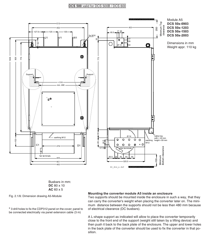
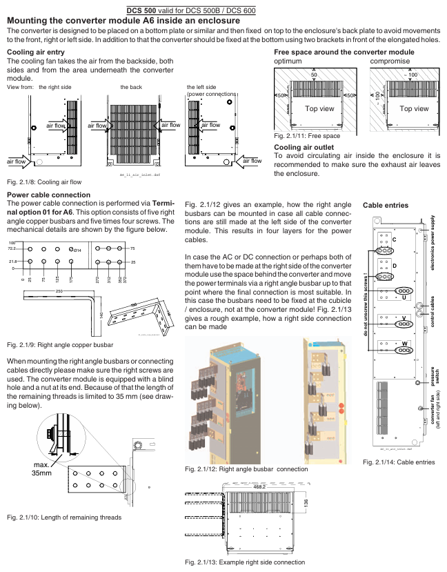
Module installation: C1/C2 modules are installed using DIN rails or 19 inch racks, while A5/A6/A7 modules require independent cabinet installation (supporting water-cooled pipe connections);
Wiring requirements: Power cables (copper bars/cables) with a cross-sectional area of 2.5-100mm ² (depending on current level), control cables need to be shielded (EMI resistant), encoder cables support differential signals (up to 150 meters long);
Environmental adaptation: Working temperature 0-50 ℃ (air-cooled), 0-40 ℃ (water-cooled), relative humidity 95% (non condensing), protection level IP20 (module)/IP54 (control cabinet).
(2) Key accessories
Accessory type, model/specification, and purpose
EMC filters NF3 series (three-phase, 25-2500A) and NF1 series (single-phase, 8-55A) suppress conducted interference, meet the EN 50081 standard, and are suitable for public grid access
The ND series of incoming reactors (ND01-ND16, inductance 50-512 μ H) reduces grid harmonics, improves power factor (cos π≥ 0.9), and protects thyristors
Residual current detection for current transformers PWS 10004 (1500A) and PWS 33001 (3300A), compatible with ground fault protection
Cooling accessories fan (CN52B2, W2E143), water-cooled radiator to ensure module heat dissipation, A7 module water-cooled flow rate ≥ 5L/min (Δ T ≤ 30 ℃)
Programming tool DriveWindow software, CDP312 panel parameter configuration, fault diagnosis, real-time monitoring, supports offline programming and online debugging
Model selection and ordering information
(1) Model coding rules
Taking "DCS 500B-0250-51-4Q" as an example, the key parameter meanings are:
500B ": Basic model;
0250 ": Output current 250A;
51 ": Voltage level 500V DC;
4Q ": Running in 4 quadrants.
(2) Core selection criteria
Motor parameters: Select the module based on the rated power of the DC motor, armature voltage/current, and excitation voltage/current (e.g. 100kW/440V motor compatible with DCS 500B-0250-51);
Application requirements: Select 4-quadrant module for energy feedback, DCS 600+AMC-DC communication board for multi motor synchronization, and water-cooled module for high temperature environment;
Power grid conditions: The public power grid needs to be equipped with EMC filters, and if the power grid harmonics are severe, line reactors need to be added.
- YOKOGAWA
- Reliance
- ADVANCED
- SEW
- ProSoft
- WATLOW
- Kongsberg
- FANUC
- VSD
- DCS
- PLC
- man-machine
- Covid-19
- Energy and Gender
- Energy Access
- Renewable Integration
- Energy Subsidies
- Energy and Water
- Net zero emission
- Energy Security
- Critical Minerals
- A-B
- petroleum
- Mine scale
- Sewage treatment
- cement
- architecture
- Industrial information
- New energy
- Automobile market
- electricity
- Construction site
- HIMA
- ABB
- Rockwell
- Schneider Modicon
- Siemens
- xYCOM
- Yaskawa
- Woodward
- BOSCH Rexroth
- MOOG
- General Electric
- American NI
- Rolls-Royce
- CTI
- Honeywell
- EMERSON
- MAN
- GE
- TRICONEX
- Control Wave
- ALSTOM
- AMAT
- STUDER
- KONGSBERG
- MOTOROLA
- DANAHER MOTION
- Bentley
- Galil
- EATON
- MOLEX
- Triconex
- DEIF
- B&W
- ZYGO
- Aerotech
- DANFOSS
- KOLLMORGEN
- Beijer
- Endress+Hauser
- schneider
- Foxboro
- KB
- REXROTH
- YAMAHA
- Johnson
- Westinghouse
- WAGO
- TOSHIBA
- TEKTRONIX
- BENDER
- BMCM
- SMC
- HITACHI
- HIRSCHMANN
- XP POWER
- Baldor
- Meggitt
- SHINKAWA
- Other Brands
- UniOP
- KUKA
- IBA
- Beckhoff
- ADLINK
-
ADLINK HPCI-14S12U - Industrial Control Backplane 12PCI Backplane PCI-14S Passive Backplane
-
ADLINK PCIe-GIE74C - image acquisition card 4-CH GigE Vision PoE+ Frame Grabber
-
ADLINK PCI-8164 - control card 4-Axis Advanced Motion Controller Board
-
ADLINK PCIe-U304 - 4 Port USB3 PCIe Frame Grabbers USB Screw Hole Card
-
ADLINK PCI-9112 - Multi-Function Data Acquisition Card DAQ Card
-
ADLINK PCI-7432 - 51-12013-0A50 4-CH Isolated Numérique I/O PCI Cartes Digital I/O Card
-
ADLINK PCA-6106P3-0C1 REV.C1 - backplane 6-Slot Passive Backplane Board
-
ADLINK PCI-7224 - 24-CH Opto-Isolated Digital I/O PCI Board
-
ADLINK CPCI-7433R(G) - Digital Input Board Rear I/O CompactPCI Card
-
ADLINK EBP-13E4 - 51-46703-0A30 Industrial PC Backplane Passive Backplane
-
ADLINK PCIE-HDV62 - Image acquisition card High Definition Video Frame Grabber
-
ADLINK EBP-13E4 - 51-46703-0A30 Industrial Backplane Board Passive Backplane
-
ADLINK 90111-B1 / CPCI-6770 - PCB CPU MODULE CompactPCI Single Board Computer
-
ADLINK PCI-7248 - DATA ACQUISITION PCI CARD 48-CH Parallel Digital I/O Board
-
ADLINK PCI-7230 - 51-12003-0a50 board PCI7230 32-CH Isolated Digital I/O Card
-
ADLINK PCI2A000CB - 51-20000-0B30 Multi-Function DAQ Card Baseboard
-
ADLINK PCI-8134-005 - 4-Axis Motion Controller Card
-
ADLINK PCI-7224 - 24-CH Opto-Isolated Digital I/O PCI Card
-
ADLINK PCI-7434 - 64-CH Isolated Digital Output Card
-
ADLINK PCI-8132 - motion control card 2-Axis Servo & Stepper Controller
-
ADLINK PCI-8134 - Motion Controller PCI Card 4-Axis Controller Board
-
ADLINK PCI-8164 - Motion Control Card 51-12406-0A40 4-Axis Controller
-
ADLINK 51-12001-0C20 - Circuit Board Data Acquisition Interface Module Hardware
-
ADLINK NuPR0-840 - industrial control motherboard Full-Size PICMG CPU Board
-
ADLINK PCI-7444 - 51-12023-0A10 card 128-CH Isolated Digital Output Board
-
ADLINK PCI-1612B - data acquisition card 4-Port RS-232/422/485 Serial Communication Card
-
ADLINK PCI-6208V 009 - 8/16-CH 16-Bit Analog Output Cards PCB-I-E-482=6BX3
-
ADLINK NUPRO-935A/LV - industrial control motherboard Full-Size PICMG SBC Board
-
ADLINK PCI-9114DG - Multi-Function DAQ Card Data Acquisition PCI Card
-
ADLINK ACL-7130 - Data acquisition card Isolated Digital I/O Board
-
ADLINK ABX-6300D-4E1-BP - board ABX6300D4E1BP Video Interface Expansion Card
-
ADLINK CPCI-6940 - CPCI-6940/D1539/M16-0(EA)-000E 6U CompactPCI Processor Board
-
ADLINK NuPRO-760 - industrial control motherboard Half-Size PICMG SBC CPU Board
-
ADLINK IMB-M42H (G)-0020 - industrial control motherboard LGA1155 Micro-ATX Mainboard
-
ADLINK RTV-24 / PCI-MP4S - 51-12519-1C30 4-Channel Real Time Video Capture Board
-
ADLINK PCI-8134 - 4-Axis Servo & Stepper Motion Controller Card
-
ADLINK MXC-6101D - V.PC000.002.ST.00 Box PC Configurable Embedded Computer
-
ADLINK PCI-8134A - 51-12421-0A10 Motion Control Card 4-Axis Controller Card
-
ADLINK DIN-100S / DIN-100SA1 - Technology SCSI-II TB 100-PIN Terminal Block Board
-
ADLINK DIN-812M001 / DIN812M001 - 51-14034-0A1 51140340A1 Terminal Module Breakout Interface
-
ADLINK PCI-8164 - Servo motion control 4-Axis Advanced Controller Card
-
ADLINK PCIe-GIE64 - Acquisition card GigE Vision PoE+ Frame Grabber
-
ADLINK M-302 - Industrial control motherboard ATX PC Board Mainboard
-
ADLINK PCI-8134 - Motion Controller PCI Card 4-Axis Controller Board
-
ADLINK PCI-RTV24 - Image capture card Analog Video Frame Grabber
-
ADLINK PCI-8102 - Motion control card 2-Axis Servo & Stepper Controller Board
-
ADLINK PCI-9112 REV.B1 - Card Multi-Function Data Acquisition Card
-
ADLINK HSI-DI32-M-N / HSL-TB32-M-DIN - Discrete I/O MODULE Distributed Automation Module System
-
ADLINK PCI-7296 - IO card REV.A3 96-CH Parallel Digital I/O Card
-
ADLINK DIN-814P-A4 / 814Y - terminal board Motion Control Interface Block
-
ADLINK DIN-814P-A4 - 51-14056-0A10 PCB-I-E-2736=ZA01 Screw Terminal Board Breakout
-
ADLINK M-322 - motherboard Industrial Control Computer Mainboard
-
ADLINK NUPRO-406 REV:B1 - industrial control motherboard Full-Size PICMG CPU Board
-
ADLINK AMP-204C - card DSP-Based 4-Axis Advanced Pulse-Train Controller
-
ADLINK HPCI14S REV.B1 - industrial computer baseboard 14-Slot Passive Backplane
-
ADLINK PCI-7250 - 8-CH Relay Output & 8-CH Isolated DI PCI Card
-
ADLINK EBP-13E2 - baseplate Passive Backplane Industrial Computer Chassis Board
-
ADLINK LPCI-3488A - PCI-GPIB card 51-12801-0A30 acquisition card IEEE-488 Interface Board
-
ADLINK PCI-6216V-GL - 51-12201-0C30 16-CH 16-Bit Voltage Analog Output Card
-
ADLINK ACL-8454 - 16-CH Isolated Digital I/O & 4-CH Counter Card
-
ADLINK HPCI-9S7U - backplane Passive Backplane Compatible with NuPRO-A301 852 841 842
-
ADLINK DAQ-2010-007 - Simultaneous-Sampling Multi-Function Data Acquisition Card
-
ADLINK MP-C154 - 51-64205-0A10 Motion Control Card 4-Axis Controller Board
-
ADLINK MXE-202/mSSD16B/WiFi-BT - Matrix Rugged I/O Platform Embedded Fanless Computer
-
ADLINK CM-920-R-17 - PC/104-Plus Single Board Computer Module Intel Celeron M
-
ADLINK PCI-7250 NSMP - 8-CH Relay Output & 8-CH Isolated DI Card
-
ADLINK PCI-8164 - 4-Axis Motion Controller PCI Card W/ Cable and Breakout Box
-
ADLINK EMX-100 - Ethernet-based 4-axis Motion Controllers Distributed Motion Module
-
ADLINK PCI-8134A - Press control card 4-Axis Motion Controller Board
-
ADLINK M-845EG REV:3.2 - industrial motherboard Pentium 4 Socket 478 Micro-ATX
-
ADLINK PCI-9114A Rev A2 DG - card High-Resolution Multi-Function Data Acquisition Board
-
ADLINK IEC-915GV - REV 1.1 Industrial motherboard Socket 478 CPU Board
-
ADLINK PCI-9111DG(G) - Data Acquisition Card Multi-Function DAQ Card
-
ADLINK HPCI-15S10 REV:B2 - Industrial computer base plate Passive Backplane Board
-
ADLINK NuPR0-840 / NuPR0-840DV - industrial control motherboard Full-size PICMG CPU Board
-
ADLINK RTV-24 / PCI-MP4S - 51-12519-1C30 4-Channel Real Time Video Capture Board
-
ADLINK NUPRO-780 - industrial control motherboard Pentium III Single Board Computer
-
ADLINK PCI-7296 - 0050 card 96-CH Opto-Isolated Parallel DIO Card Set
-
ADLINK NUPRO-780 - industrial control motherboard PICMG Full-Size SBC
-
ADLINK PCI-7248 - 51-12006-0A3 002 Pci 7248 48-CH Parallel Digital I/O Card
-
ADLINK PCI-7230 - 32-CH Isolated Digital I/O Card
-
ADLINK AMP-204C - motion control card 4-Axis Advanced Controller Board
-
ADLINK PCI-1714UL - Card Ultra High-Speed 4-CH Simultaneous Sampling DAQ
-
ADLINK NuPRO-E330 - industrial computer equipment motherboard PICMG 1.3 SHB SBC
-
ADLINK AMP-204C - DSP-Based 4-Axis Advanced Pulse-Train Motion Controller Module
-
ADLINK PCI-7256 - 001 51-12206-0A2 REV.A2 LPCI-7256 16-CH Latching Relay Output Card
-
ADLINK ND6050 - NUDAM DIGITAL I/0 MODULE Distributed I/O Unit
-
ASEM BM100 - Box PC Embedded Fanless Industrial Computer
-
ADLINK PCI-7250 - PCI Acquisition Card 8-CH Relay Output & Isolated DI Board
-
ADLINK PCI-8164 - Servo motion control 4-Axis Controller Card
-
ADLINK NuPRO-A40H - Industrial Motherboard 51-41807-1A30 OSP LGA1155 H61
-
ADLINK ADMAX X300 SERVER - 51066010-0A30 motherboard Multi-Processor Mainboard
-
ADLINK CMe-GIE62+ - 51-32903-0A30 control card PC/104-Plus GigE Vision Frame Grabber
-
ADLINK NUPRO-780 - industrial control motherboard Full-Size PICMG SBC CPU Board
-
ADLINK ETX-AT-N270-18/GKTEL - 51-71111-OB10 motherboard ETX CPU Module Board
-
ADLINK DIN-812M - interface module Terminal Block Connection Board
-
ADLINK IMB-M42H - industrial control motherboard LGA1155 Micro-ATX Mainboard
-
ADLINK PXIS-2508 - 8-slot 3U PXI Instrument Chassis Power Hardware Assembly
-
ADLINK AMP-208C - Motion Control card DSP-Based 8-Axis Pulse-Train Controller
-
ADLINK PCI-9111 / PCI-9111DG - Multi-Function Data Acquisition Card DAQ Board
-
ADLINK IEEE-488 GPIB card - Bus Interface Controller Communication Board
-
ADLINK RTV-24 - 51-12519-1C30 image acquisition card Video Frame Grabber Card
-
ADLINK TB-24P/24-01 - Board 24 Way Screw Terminal Breakout Board
-
ADLINK HSL-DI16DO16-DB-NN - 51-23015-0A40 Distributed Discrete I/O Module Set
-
ADLINK PCI-7442 - switch quantity card data acquisition card 64-CH Isolated Card
-
ADLINK ACL-7130 REV. B2 - industrial control capture card Isolated Digital I/O PCI Card
-
ADLINK PCI-6S / PCI6S - Backplane 6-Slot Passive Backplane Chassis Board
-
ADLINK ACL-8113A - card Isolated Digital Input Card
-
ADLINK CPCI-6208V-003 - board cPCI CompactPCI 8-CH Analog Output Card
-
ADLINK DIN-100S-01(G) - SCSI 100-Pin Terminal Block Interface Board
-
ADLINK PCI-7433 - Isolated Digital Input Card 64-CH
-
ADLINK PCI-9812 - Synchronous sampling analog input card High-Speed DAQ Board
-
ADLINK PCI-7434 REV.B1 - PLOTECH PCB-I-E-1182=6EX2 64-CH Isolated Digital Output Card
-
ADLINK PCIe-RTV24 - 51-18016-0A20 4-CH Real-Time Video Capture Card PCIe Frame Grabber
-
ADLINK PCI-8144 / PCI-8144N - Motion control card 4-Axis Stepper Motor Controller
-
ADLINK DIN-68S-01 - terminal board 68-Pin Connector Terminal Block
-
ADLINK MP-C154 - Motion control card 4-Axis Advanced Controller Card
-
ADLINK PCI-7248 (G) - Motherboard 48-CH Parallel Digital I/O Card
-
ADLINK MXE-1301(G) - Intel Atom D2550+NM10 MXE 1300 Series 93-4130-0030 Embedded Computer
-
ADLINK PRO-841 Rev 2.0 / PRO-060907000670 - CPU 2.26GHz & RAM Industrial PC Board
-
ADLINK NuPRO-E330 - Industrial Motherboard System Host Board PICMG 1.3 SHB
-
ADLINK EBP-13E2 - Passive Backplane Industrial Chassis Baseboard
-
ADLINK PCI-8154 - 4-axis Motion Control Card Servo & Stepper Controller Board
-
ADLINK NuPrO-596 REV.B1 - industrial control motherboard Half-size PICMG CPU Board
-
ADLINK PCI-7852 / PCI-7851 - PLOTECH High-Speed Link Control Card Interface Board
-
ADLINK PCI-9112 - 51-12252-0D20 data acquisition card Multi-Function DAQ
-
ADLINK PCI-9112 - Circuit Board 51-12252-0C20 Multi-Function Data Acquisition Card
-
ADLINK NUPRO-761 REV:1.1 - industrial control motherboard PICMG Full-Size CPU Board

K-JIANG

Add: Jimei North Road, Jimei District, Xiamen, Fujian, China
Tell:+86-15305925923