
K-WANG


GE Qualitrol IC670ALG230 Analog Input Module
Product core positioning and application scenarios
IC670ALG230 is a current source analog input module launched by Qualitrol (now under GE). Its core function is to accurately convert the current signals (0-20 mA or 4-20 mA) output by 2-wire, 3-wire, or 4-wire sensors/transmitters in industrial fields into digital signals, which are transmitted to the GE field control system (with a bus interface unit BIU) to achieve real-time acquisition and monitoring of process parameters such as pressure, temperature, and flow rate. Its typical application scenarios cover industrial fields such as power, petrochemicals, and manufacturing, and are suitable for automation systems that require high accuracy of analog signals and centralized collection of multi-channel current signals.
Core technical specifications
(1) Basic parameters of module
Category specific specification description
Channel configuration with 8 single ended grouped inputs (shared signal ground) and 8 inputs sharing the same 24 VDC power supply and signal common terminal, suitable for centralized collection of signals from similar sensors
Software configurable input signal range: 0-20 mA (default), 4-20 mA supports industrial standard current signals, 4-20 mA mode can detect wire breakage faults (input
GE Qualitrol IC670ALG230 Analog Input Module
Product core positioning and application scenarios
IC670ALG230 is a current source analog input module launched by Qualitrol (now under GE). Its core function is to accurately convert the current signals (0-20 mA or 4-20 mA) output by 2-wire, 3-wire, or 4-wire sensors/transmitters in industrial fields into digital signals, which are transmitted to the GE field control system (with a bus interface unit BIU) to achieve real-time acquisition and monitoring of process parameters such as pressure, temperature, and flow rate. Its typical application scenarios cover industrial fields such as power, petrochemicals, and manufacturing, and are suitable for automation systems that require high accuracy of analog signals and centralized collection of multi-channel current signals.
Core technical specifications
(1) Basic parameters of module
Category specific specification description
Channel configuration with 8 single ended grouped inputs (shared signal ground) and 8 inputs sharing the same 24 VDC power supply and signal common terminal, suitable for centralized collection of signals from similar sensors
Software configurable input signal range: 0-20 mA (default), 4-20 mA supports industrial standard current signals, 4-20 mA mode can detect wire breakage faults (input<2.0 mA triggers diagnosis)
Power supply requirement: Power supply voltage: 18-30 VDC (typical 24 VDC); Module power consumption: 50 mA (module only), 210 mA (including loop current) can share 24 VDC power supply with bus interface unit (BIU), please note that the total current load does not exceed the limit value
Isolation performance for ground and logic isolation: 1500 VAC (1-minute withstand), 250 VAC (continuous withstand), high isolation level to suppress industrial field grounding loops and electromagnetic interference (EMI), protect modules and backend systems
(2) Signal Conversion and Accuracy
Category specific specifications Technical advantages
Resolution: Digital resolution of 12 bits, analog resolution of 5.0 μ A, high-precision conversion ensures that small current changes can be recognized (such as a minimum resolution of 4 μ A changes under 4-20 mA signals)
Conversion speed of approximately 60 μ s per channel (1 MHz clock). Fast conversion supports high-frequency data acquisition and is suitable for dynamic process monitoring (such as rapidly changing pressure signals)
Measurement accuracy at 25 ℃ ± 0.05% full range (0.1-20 mA input), non-linear error ± 0.025% full range high precision meets industrial level process control requirements, reducing the impact of signal acquisition errors on control logic
Typical temperature coefficient is ± 0.002%/℃, with a maximum of ± 0.005%/℃. Within a wide temperature range (commonly seen in industrial sites -10-60 ℃), the accuracy attenuation is small, making it suitable for complex environments
(3) Input protection and anti-interference
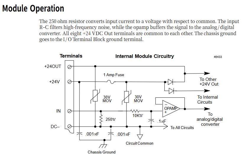
Overcurrent protection: maximum input current of 30 mA, built-in 1 A fuse (24V output circuit) to prevent overcurrent damage caused by sensor failure;
Overvoltage protection: 30 V MOV (metal oxide varistor) to suppress voltage spikes on the power supply side;
Filter design: A first-order RC filter with 250 Ω resistor and 0.1 μ F capacitor connected in series for each channel, with a transition frequency of approximately 160 Hz, to filter out high-frequency noise;
Wire breakage detection: Only 4-20 mA mode is supported. When the input current is less than 2.0 mA, the BIU triggers wire breakage diagnosis for timely troubleshooting of sensor faults.
Hardware Design and Working Principle
(1) Internal circuit structure
The core circuit of the module revolves around "current voltage conversion+signal conditioning+A/D conversion", and the key path is as follows:
Signal input: After the current signal of the on-site sensor is connected to the channel, it first passes through a 250 Ω precision resistor to convert the current signal into a voltage signal (such as 20 mA corresponding to 5 V voltage);
Filtering and buffering: After the RC filter filters out high-frequency noise, the signal is buffered by an operational amplifier (OPAMP) to avoid load effects affecting measurement accuracy;
A/D conversion: A 12 bit A/D converter converts analog voltage into digital signal, and the conversion result is temporarily stored in an 8-word (16 byte) data buffer inside the module;
Data transmission: Unscaled digital data is transmitted to the host or local processor through a bus interface unit (BIU), and the BIU performs engineering unit scaling (such as mapping 4-20 mA to 0-100 ℃).
(2) Status indication and wiring
LED indicator light: The transparent area at the top of the module is equipped with an LED, which lights up under the conditions of "backplane power supply+normal on-site power supply+fuse not blown" to visually determine the power supply status of the module;
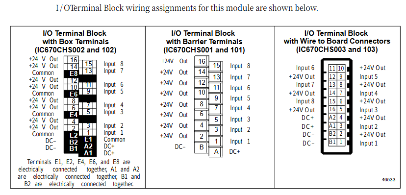
Terminal layout: Using standardized I/O terminal blocks (supporting box type terminals IC670CHS002/102, fence type terminals IC670CHS001/101, and wire to board connectors IC670CHS003/103), the key terminals include:
+24 V Out ": 8 channels of shared 24 V output (with fuses), providing loop power for 2-wire transmitters;
Input 1-8 ": 8-channel current signal input terminal;
DC - "/" Common ": The signal common terminal needs to be connected to the sensor signal ground to avoid grounding loops;
Chassis Ground ": The module casing ground needs to be short circuited to the control cabinet casing to enhance anti-interference capability.
On site wiring and sensor adaptation
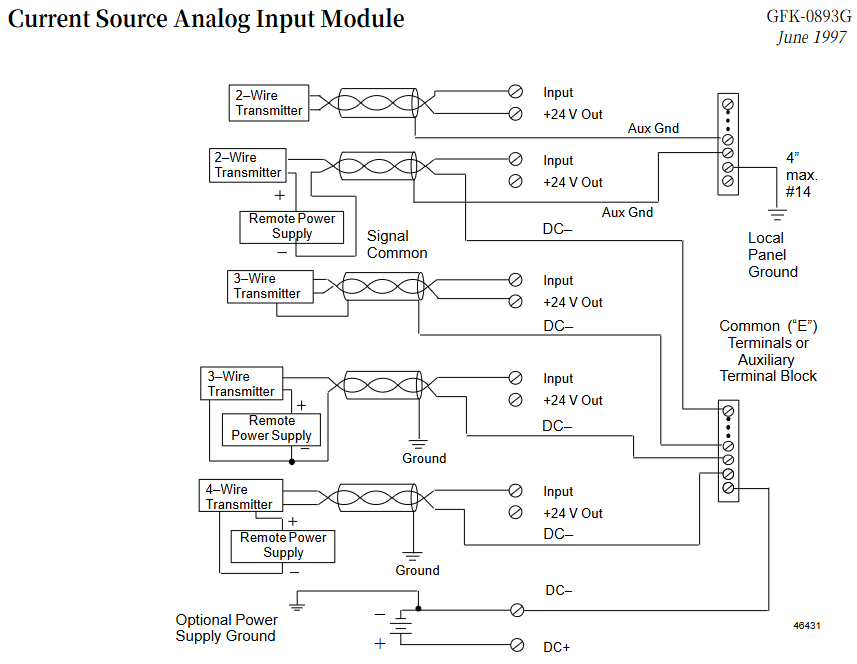
The module supports 2-wire, 3-wire, and 4-wire sensors/transmitters, and the wiring method needs to be selected according to the sensor type. The key configurations are as follows:
(1) 2-wire transmitter (loop power supply)
Wiring characteristics: The sensor power supply and signal share two wires. The module "+24 V Out" provides circuit power, "Input" receives current signals, and "DC -" is the common terminal;
Attention: AWG # 14- # 22 (cross-sectional area 0.36-2.1 mm ²) should be used as the wire, and the recommended maximum wiring distance should not exceed 100 meters (to avoid voltage drop causing insufficient sensor power supply); The shielding layer needs to be grounded separately and not shared with the power supply ground.
(2) 3-wire transmitter (independent power supply+signal)
Wiring characteristics: The sensor requires separate power supply (module "+24 V Out" or external power supply can be used), the signal terminal "+" is connected to module "Input", "-" is connected to "DC -", and the power supply "-" and signal "-" are grounded together;
Adaptation scenario: For sensors that require higher power supply voltage or current (such as some high-precision temperature transmitters), it is recommended to use an auxiliary terminal block to consolidate the common terminal and simplify wiring.
(3) 4-wire transmitter (completely isolated)
Wiring characteristics: The sensor power supply is completely isolated from the signal (independent external power supply), the signal "+" is connected to "Input", "-" is connected to "DC -", and the power ground and signal ground are separated to avoid ground loop interference;
Advantages: Suitable for long-distance (such as over 200 meters) or strong interference scenarios (such as near frequency converters), isolation design improves signal stability.
(4) Wiring specifications
Wire selection: It is recommended to use shielded twisted pair for analog signals, with the shielding layer grounded at one end (preferably on the module side);
Grounding requirements: Only ground the signal common terminal on the module side to avoid multiple grounding points forming a ground loop; The module 'Chassis Ground' needs to be connected to the control cabinet casing with a short wire (recommended<4 inches, # 14 wire);
Auxiliary terminal block: When using fence type terminals or wire to board connectors, auxiliary terminal blocks (such as IC670CHS series) should be used to expand the wiring terminals. All terminals inside the auxiliary terminal block are connected and can be used to summarize the common terminal or power terminal.
Software Configuration and Data Processing
(1) Parameter configuration
The module needs to be parameterized through a Bus Interface Unit (BIU) or host software, with the following key configuration items:
Input range: Each channel is independently configured with 0-20 mA or 4-20 mA, with a default range of 0-20 mA;
Engineering unit scaling: defined by BIU as "Engineering Lower Limit (Eng Lo) - Engineering Upper Limit (Eng Hi)" and "Integer Lower Limit (Int Lo) - Integer Upper Limit (Int Hi)", default scaling is Eng Lo=0, Eng Hi=20000 (corresponding to 0-20 mA), Int Lo=0, Int Hi=20000;
Diagnostic enablement: Enable disconnection diagnosis (triggered by input<2.0 mA) and over range diagnosis (triggered by input>20.5 mA) in 4-20 mA mode.
(2) Data transmission
Data format: 8 inputs correspond to 8 16 bit digital quantities (unsigned integers), stored in the module data buffer, and periodically read by BIU (read cycle depends on system configuration, typically 10-100 ms);
Scaling logic: Taking the mapping of 4-20 mA to 0-100 ℃ as an example, BIU calculates the engineering value according to the following formula:
Engineering value=Eng Lo+Int Hi − Int Lo
Digital quantity - Int Lo × (Eng Hi - Eng Lo) (Example: When the digital quantity is 8000, the corresponding current is 8 mA, and the engineering value is 25 ℃).
- YOKOGAWA
- Reliance
- ADVANCED
- SEW
- ProSoft
- WATLOW
- Kongsberg
- FANUC
- VSD
- DCS
- PLC
- man-machine
- Covid-19
- Energy and Gender
- Energy Access
- Renewable Integration
- Energy Subsidies
- Energy and Water
- Net zero emission
- Energy Security
- Critical Minerals
- A-B
- petroleum
- Mine scale
- Sewage treatment
- cement
- architecture
- Industrial information
- New energy
- Automobile market
- electricity
- Construction site
- HIMA
- ABB
- Rockwell
- Schneider Modicon
- Siemens
- xYCOM
- Yaskawa
- Woodward
- BOSCH Rexroth
- MOOG
- General Electric
- American NI
- Rolls-Royce
- CTI
- Honeywell
- EMERSON
- MAN
- GE
- TRICONEX
- Control Wave
- ALSTOM
- AMAT
- STUDER
- KONGSBERG
- MOTOROLA
- DANAHER MOTION
- Bentley
- Galil
- EATON
- MOLEX
- Triconex
- DEIF
- B&W
- ZYGO
- Aerotech
- DANFOSS
- KOLLMORGEN
- Beijer
- Endress+Hauser
- schneider
- Foxboro
- KB
- REXROTH
- YAMAHA
- Johnson
- Westinghouse
- WAGO
- TOSHIBA
- TEKTRONIX
- BENDER
- BMCM
- SMC
- HITACHI
- HIRSCHMANN
- XP POWER
- Baldor
- Meggitt
- SHINKAWA
- Other Brands
- UniOP
- KUKA
- IBA
- Beckhoff
- ADLINK
-
ADLINK HPCI-14S12U - Industrial Control Backplane 12PCI Backplane PCI-14S Passive Backplane
-
ADLINK PCIe-GIE74C - image acquisition card 4-CH GigE Vision PoE+ Frame Grabber
-
ADLINK PCI-8164 - control card 4-Axis Advanced Motion Controller Board
-
ADLINK PCIe-U304 - 4 Port USB3 PCIe Frame Grabbers USB Screw Hole Card
-
ADLINK PCI-9112 - Multi-Function Data Acquisition Card DAQ Card
-
ADLINK PCI-7432 - 51-12013-0A50 4-CH Isolated Numérique I/O PCI Cartes Digital I/O Card
-
ADLINK PCA-6106P3-0C1 REV.C1 - backplane 6-Slot Passive Backplane Board
-
ADLINK PCI-7224 - 24-CH Opto-Isolated Digital I/O PCI Board
-
ADLINK CPCI-7433R(G) - Digital Input Board Rear I/O CompactPCI Card
-
ADLINK EBP-13E4 - 51-46703-0A30 Industrial PC Backplane Passive Backplane
-
ADLINK PCIE-HDV62 - Image acquisition card High Definition Video Frame Grabber
-
ADLINK EBP-13E4 - 51-46703-0A30 Industrial Backplane Board Passive Backplane
-
ADLINK 90111-B1 / CPCI-6770 - PCB CPU MODULE CompactPCI Single Board Computer
-
ADLINK PCI-7248 - DATA ACQUISITION PCI CARD 48-CH Parallel Digital I/O Board
-
ADLINK PCI-7230 - 51-12003-0a50 board PCI7230 32-CH Isolated Digital I/O Card
-
ADLINK PCI2A000CB - 51-20000-0B30 Multi-Function DAQ Card Baseboard
-
ADLINK PCI-8134-005 - 4-Axis Motion Controller Card
-
ADLINK PCI-7224 - 24-CH Opto-Isolated Digital I/O PCI Card
-
ADLINK PCI-7434 - 64-CH Isolated Digital Output Card
-
ADLINK PCI-8132 - motion control card 2-Axis Servo & Stepper Controller
-
ADLINK PCI-8134 - Motion Controller PCI Card 4-Axis Controller Board
-
ADLINK PCI-8164 - Motion Control Card 51-12406-0A40 4-Axis Controller
-
ADLINK 51-12001-0C20 - Circuit Board Data Acquisition Interface Module Hardware
-
ADLINK NuPR0-840 - industrial control motherboard Full-Size PICMG CPU Board
-
ADLINK PCI-7444 - 51-12023-0A10 card 128-CH Isolated Digital Output Board
-
ADLINK PCI-1612B - data acquisition card 4-Port RS-232/422/485 Serial Communication Card
-
ADLINK PCI-6208V 009 - 8/16-CH 16-Bit Analog Output Cards PCB-I-E-482=6BX3
-
ADLINK NUPRO-935A/LV - industrial control motherboard Full-Size PICMG SBC Board
-
ADLINK PCI-9114DG - Multi-Function DAQ Card Data Acquisition PCI Card
-
ADLINK ACL-7130 - Data acquisition card Isolated Digital I/O Board
-
ADLINK ABX-6300D-4E1-BP - board ABX6300D4E1BP Video Interface Expansion Card
-
ADLINK CPCI-6940 - CPCI-6940/D1539/M16-0(EA)-000E 6U CompactPCI Processor Board
-
ADLINK NuPRO-760 - industrial control motherboard Half-Size PICMG SBC CPU Board
-
ADLINK IMB-M42H (G)-0020 - industrial control motherboard LGA1155 Micro-ATX Mainboard
-
ADLINK RTV-24 / PCI-MP4S - 51-12519-1C30 4-Channel Real Time Video Capture Board
-
ADLINK PCI-8134 - 4-Axis Servo & Stepper Motion Controller Card
-
ADLINK MXC-6101D - V.PC000.002.ST.00 Box PC Configurable Embedded Computer
-
ADLINK PCI-8134A - 51-12421-0A10 Motion Control Card 4-Axis Controller Card
-
ADLINK DIN-100S / DIN-100SA1 - Technology SCSI-II TB 100-PIN Terminal Block Board
-
ADLINK DIN-812M001 / DIN812M001 - 51-14034-0A1 51140340A1 Terminal Module Breakout Interface
-
ADLINK PCI-8164 - Servo motion control 4-Axis Advanced Controller Card
-
ADLINK PCIe-GIE64 - Acquisition card GigE Vision PoE+ Frame Grabber
-
ADLINK M-302 - Industrial control motherboard ATX PC Board Mainboard
-
ADLINK PCI-8134 - Motion Controller PCI Card 4-Axis Controller Board
-
ADLINK PCI-RTV24 - Image capture card Analog Video Frame Grabber
-
ADLINK PCI-8102 - Motion control card 2-Axis Servo & Stepper Controller Board
-
ADLINK PCI-9112 REV.B1 - Card Multi-Function Data Acquisition Card
-
ADLINK HSI-DI32-M-N / HSL-TB32-M-DIN - Discrete I/O MODULE Distributed Automation Module System
-
ADLINK PCI-7296 - IO card REV.A3 96-CH Parallel Digital I/O Card
-
ADLINK DIN-814P-A4 / 814Y - terminal board Motion Control Interface Block
-
ADLINK DIN-814P-A4 - 51-14056-0A10 PCB-I-E-2736=ZA01 Screw Terminal Board Breakout
-
ADLINK M-322 - motherboard Industrial Control Computer Mainboard
-
ADLINK NUPRO-406 REV:B1 - industrial control motherboard Full-Size PICMG CPU Board
-
ADLINK AMP-204C - card DSP-Based 4-Axis Advanced Pulse-Train Controller
-
ADLINK HPCI14S REV.B1 - industrial computer baseboard 14-Slot Passive Backplane
-
ADLINK PCI-7250 - 8-CH Relay Output & 8-CH Isolated DI PCI Card
-
ADLINK EBP-13E2 - baseplate Passive Backplane Industrial Computer Chassis Board
-
ADLINK LPCI-3488A - PCI-GPIB card 51-12801-0A30 acquisition card IEEE-488 Interface Board
-
ADLINK PCI-6216V-GL - 51-12201-0C30 16-CH 16-Bit Voltage Analog Output Card
-
ADLINK ACL-8454 - 16-CH Isolated Digital I/O & 4-CH Counter Card
-
ADLINK HPCI-9S7U - backplane Passive Backplane Compatible with NuPRO-A301 852 841 842
-
ADLINK DAQ-2010-007 - Simultaneous-Sampling Multi-Function Data Acquisition Card
-
ADLINK MP-C154 - 51-64205-0A10 Motion Control Card 4-Axis Controller Board
-
ADLINK MXE-202/mSSD16B/WiFi-BT - Matrix Rugged I/O Platform Embedded Fanless Computer
-
ADLINK CM-920-R-17 - PC/104-Plus Single Board Computer Module Intel Celeron M
-
ADLINK PCI-7250 NSMP - 8-CH Relay Output & 8-CH Isolated DI Card
-
ADLINK PCI-8164 - 4-Axis Motion Controller PCI Card W/ Cable and Breakout Box
-
ADLINK EMX-100 - Ethernet-based 4-axis Motion Controllers Distributed Motion Module
-
ADLINK PCI-8134A - Press control card 4-Axis Motion Controller Board
-
ADLINK M-845EG REV:3.2 - industrial motherboard Pentium 4 Socket 478 Micro-ATX
-
ADLINK PCI-9114A Rev A2 DG - card High-Resolution Multi-Function Data Acquisition Board
-
ADLINK IEC-915GV - REV 1.1 Industrial motherboard Socket 478 CPU Board
-
ADLINK PCI-9111DG(G) - Data Acquisition Card Multi-Function DAQ Card
-
ADLINK HPCI-15S10 REV:B2 - Industrial computer base plate Passive Backplane Board
-
ADLINK NuPR0-840 / NuPR0-840DV - industrial control motherboard Full-size PICMG CPU Board
-
ADLINK RTV-24 / PCI-MP4S - 51-12519-1C30 4-Channel Real Time Video Capture Board
-
ADLINK NUPRO-780 - industrial control motherboard Pentium III Single Board Computer
-
ADLINK PCI-7296 - 0050 card 96-CH Opto-Isolated Parallel DIO Card Set
-
ADLINK NUPRO-780 - industrial control motherboard PICMG Full-Size SBC
-
ADLINK PCI-7248 - 51-12006-0A3 002 Pci 7248 48-CH Parallel Digital I/O Card
-
ADLINK PCI-7230 - 32-CH Isolated Digital I/O Card
-
ADLINK AMP-204C - motion control card 4-Axis Advanced Controller Board
-
ADLINK PCI-1714UL - Card Ultra High-Speed 4-CH Simultaneous Sampling DAQ
-
ADLINK NuPRO-E330 - industrial computer equipment motherboard PICMG 1.3 SHB SBC
-
ADLINK AMP-204C - DSP-Based 4-Axis Advanced Pulse-Train Motion Controller Module
-
ADLINK PCI-7256 - 001 51-12206-0A2 REV.A2 LPCI-7256 16-CH Latching Relay Output Card
-
ADLINK ND6050 - NUDAM DIGITAL I/0 MODULE Distributed I/O Unit
-
ASEM BM100 - Box PC Embedded Fanless Industrial Computer
-
ADLINK PCI-7250 - PCI Acquisition Card 8-CH Relay Output & Isolated DI Board
-
ADLINK PCI-8164 - Servo motion control 4-Axis Controller Card
-
ADLINK NuPRO-A40H - Industrial Motherboard 51-41807-1A30 OSP LGA1155 H61
-
ADLINK ADMAX X300 SERVER - 51066010-0A30 motherboard Multi-Processor Mainboard
-
ADLINK CMe-GIE62+ - 51-32903-0A30 control card PC/104-Plus GigE Vision Frame Grabber
-
ADLINK NUPRO-780 - industrial control motherboard Full-Size PICMG SBC CPU Board
-
ADLINK ETX-AT-N270-18/GKTEL - 51-71111-OB10 motherboard ETX CPU Module Board
-
ADLINK DIN-812M - interface module Terminal Block Connection Board
-
ADLINK IMB-M42H - industrial control motherboard LGA1155 Micro-ATX Mainboard
-
ADLINK PXIS-2508 - 8-slot 3U PXI Instrument Chassis Power Hardware Assembly
-
ADLINK AMP-208C - Motion Control card DSP-Based 8-Axis Pulse-Train Controller
-
ADLINK PCI-9111 / PCI-9111DG - Multi-Function Data Acquisition Card DAQ Board
-
ADLINK IEEE-488 GPIB card - Bus Interface Controller Communication Board
-
ADLINK RTV-24 - 51-12519-1C30 image acquisition card Video Frame Grabber Card
-
ADLINK TB-24P/24-01 - Board 24 Way Screw Terminal Breakout Board
-
ADLINK HSL-DI16DO16-DB-NN - 51-23015-0A40 Distributed Discrete I/O Module Set
-
ADLINK PCI-7442 - switch quantity card data acquisition card 64-CH Isolated Card
-
ADLINK ACL-7130 REV. B2 - industrial control capture card Isolated Digital I/O PCI Card
-
ADLINK PCI-6S / PCI6S - Backplane 6-Slot Passive Backplane Chassis Board
-
ADLINK ACL-8113A - card Isolated Digital Input Card
-
ADLINK CPCI-6208V-003 - board cPCI CompactPCI 8-CH Analog Output Card
-
ADLINK DIN-100S-01(G) - SCSI 100-Pin Terminal Block Interface Board
-
ADLINK PCI-7433 - Isolated Digital Input Card 64-CH
-
ADLINK PCI-9812 - Synchronous sampling analog input card High-Speed DAQ Board
-
ADLINK PCI-7434 REV.B1 - PLOTECH PCB-I-E-1182=6EX2 64-CH Isolated Digital Output Card
-
ADLINK PCIe-RTV24 - 51-18016-0A20 4-CH Real-Time Video Capture Card PCIe Frame Grabber
-
ADLINK PCI-8144 / PCI-8144N - Motion control card 4-Axis Stepper Motor Controller
-
ADLINK DIN-68S-01 - terminal board 68-Pin Connector Terminal Block
-
ADLINK MP-C154 - Motion control card 4-Axis Advanced Controller Card
-
ADLINK PCI-7248 (G) - Motherboard 48-CH Parallel Digital I/O Card
-
ADLINK MXE-1301(G) - Intel Atom D2550+NM10 MXE 1300 Series 93-4130-0030 Embedded Computer
-
ADLINK PRO-841 Rev 2.0 / PRO-060907000670 - CPU 2.26GHz & RAM Industrial PC Board
-
ADLINK NuPRO-E330 - Industrial Motherboard System Host Board PICMG 1.3 SHB
-
ADLINK EBP-13E2 - Passive Backplane Industrial Chassis Baseboard
-
ADLINK PCI-8154 - 4-axis Motion Control Card Servo & Stepper Controller Board
-
ADLINK NuPrO-596 REV.B1 - industrial control motherboard Half-size PICMG CPU Board
-
ADLINK PCI-7852 / PCI-7851 - PLOTECH High-Speed Link Control Card Interface Board
-
ADLINK PCI-9112 - 51-12252-0D20 data acquisition card Multi-Function DAQ
-
ADLINK PCI-9112 - Circuit Board 51-12252-0C20 Multi-Function Data Acquisition Card
-
ADLINK NUPRO-761 REV:1.1 - industrial control motherboard PICMG Full-Size CPU Board

K-JIANG

Add: Jimei North Road, Jimei District, Xiamen, Fujian, China
Tell:+86-15305925923