
K-WANG
+086-15305925923
Service expert in industrial control field!


Product
Article
NameDescriptionContent
Adequate Inventory, Timely Service
pursuit of excellence


Ship control system
Equipment control system
Power monitoring system
Current position:
新闻动态
newS
Brand
ABB DCS800 Drives
ABB DCS800 Drives
ABB DCS800 Drives
What this chapter contains
This chapter contains the safety instructions which you must follow when installing,
operating and servicing the drive. If ignored, physical injury or death may follow, or
damage may occur to the drive, the motor or driven equipment. Read the safety
instructions before you work on the unit.
To which products this chapter applies
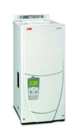
The information is valid for the whole range of the product DCS800, the converter
modules DCS800-S0x size D1 to D7, field exciter units DCF80x, etc. like the Rebuild
Kit DCS800-R00-9xxx.
Use of warnings and notes
There are two types of safety instructions throughout this manual: warnings and
notes. Warnings caution you about conditions which can result in serious injury or
death and/or damage to the equipment. They also tell you how to avoid the danger.
Notes draw attention to a particular condition or fact, or give information on a
subject. The warning symbols are used as follows:
Dangerous voltage warning warns of high voltage which can cause
physical injury and/or damage to the equipment.
General danger warning warns about conditions, other than those
caused by electricity, which can result in physical injury or death and/or
damage to the equipment.
Electrostatic sensitive discharge warning warns of electrostatic
discharge which can damage the equipment.
These warnings are intended for all who work on the drive, motor cable or motor.
Ignoring the instructions can cause physical injury or death and/or damage to the
equipment..
WARNING!
• Only qualified electricians are allowed to install and maintain the drive!
• Never work on the drive, motor cable or motor when main power is applied.
Always ensure by measuring with a multimeter (impedance at least 1 Mohm)
that:
1. Voltage between drive input phases U1, V1 and W1 and the frame is
close to 0 V.
2. Voltage between terminals C+ and D- and the frame is close to 0 V.
• Do not work on the control cables when power is applied to the drive or to the
external control circuits. Externally supplied control circuits may cause
dangerous voltages inside the drive even when the main power on the drive is
switched off.
• Do not make any insulation resistance or voltage withstand tests on the drive or
drive modules.
• Isolate the motor cables from the drive when testing the insulation resistance or
voltage withstand of the cables or the motor.
• When reconnecting the motor cable, always check that the C+ and D- cables
are connected with the proper terminal.
Note:
• The motor cable terminals on the drive are at a dangerously high voltage when
the main power is on, regardless of whether the motor is running or not.
• Depending on the external wiring, dangerous voltages (115 V, 220 V or 230 V)
may be present on the relay outputs of the drive system (e.g. SDCS-IOB-2 and
RDIO).
• DCS800 with enclosure extension: Before working on the drive, isolate the
whole drive from the supply
These instructions are intended for all who are responsible for the grounding of the
drive. Incorrect grounding can cause physical injury, death and/or equipment
malfunction and increase electromagnetic interference.
WARNING!
• Ground the drive, motor and adjoining equipment to ensure personnel safety in
all circumstances, and to reduce electromagnetic emission and pick-up.
• Make sure that grounding conductors are adequately sized and marked as
required by safety regulations.
• In a multiple-drive installation, connect each drive separately to protective
earth (PE ).
• Minimize EMC emission and make a 360° high frequency grounding (e.g.
conductive sleeves) of screened cable entries at the cabinet lead-through
plate.
• Do not install a drive equipped with an EMC filter to an ungrounded power
system or a high resistance-grounded (over 30 ohms) power system.
Note:
• Power cable shields are suitable as equipment grounding conductors only
when adequately sized to meet safety regulations.
• As the normal leakage current of the drive is higher than 3.5 mA AC or 10 mA
DC (stated by EN 50178, 5.2.11.1), a fixed protective earth connection is
required.
These instructions are intended for all who handle the circuit boards and fiber optic
cables. Ignoring the following instructions can cause damage to the equipment.
WARNING! The printed circuit boards contain components sensitive to electrostatic
discharge. Wear a grounding wrist band when handling the boards. Do not touch the
boards unnecessarily.
Use grounding strip:
ABB order no.: 3ADV050035P0001
WARNING! Handle the fiber optic cables with care. When unplugging optic cables,
always grab the connector, not the cable itself. Do not touch the ends of the fibers
with bare hands as the fiber is extremely sensitive to dirt. The minimum allowed
bend radius is 35 mm (1.4 in.).
Mechanical installation
These notes are intended for all who install the drive. Handle the unit carefully to
avoid damage and injury.
WARNING!
• DCS800 sizes D4 ... D7: The drive is heavy. Do not lift it alone. Do not lift the
unit by the front cover. Place units D4, D4+ and D5 only on their back.
DCS800 sizes D5 ... D7: The drive is heavy. Lift the drive by the lifting lugs
only. Do not tilt the unit. The unit will overturn from a tilt of about 6 degrees.
• Make sure that dust from drilling does not enter the drive when installing.
Electrically conductive dust inside the unit may cause damage or lead to
malfunction.
• Ensure sufficient cooling.
• Do not fasten the drive by riveting or welding
These warnings are intended for all who plan the operation of the drive or operate
the drive. Ignoring the instructions can cause physical injury or death and/or damage
to the equipment.
WARNING!
• Before adjusting the drive and putting it into service, make sure that the motor
and all driven equipment are suitable for operation throughout the speed range
provided by the drive. The drive can be adjusted to operate the motor at
speeds above and below the base speed.
• Do not control the motor with the disconnecting device (disconnecting mains);
instead, use the control panel keys and , or commands via the I/O
board of the drive.
• Mains connection
You can use a disconnect switch (with fuses) to disconnect the electrical
components of the drive from the mains for installation and maintenance work.
The type of disconnect switch used must be as per EN 60947-3, Class B, so as
to comply with EU regulations, or a circuit-breaker type which switches off the
load circuit by means of an auxiliary contact causing the breaker's main
contacts to open. The mains disconnect must be locked in its "OPEN" position
during any installation and maintenance work.
• EMERGENCY STOP buttons must be installed at each control desk and at all
other control panels requiring an emergency stop function. Pressing the STOP
button on the control panel of the drive will neither cause an emergency stop of
the motor, nor will the drive be disconnected from any dangerous potential.
To avoid unintentional operating states, or to shut the unit down in case of any
imminent danger according to the standards in the safety instructions it is not
sufficient to merely shut down the drive via signals "RUN", "drive OFF" or
"Emergency Stop" respectively "control panel" or "PC tool".
• Intended use
The operating instructions cannot take into consideration every possible case
of configuration, operation or maintenance. Thus, they mainly give such advice
only, which is required by qualified personnel for normal operation of the
machines and devices in industrial installations.
If in special cases the electrical machines and devices are in-tended for use in
non-industrial installations - which may require stricter safety regulations (e.g.
protection against contact by children or similar) - these additional safety
measures for the installation must be provided by the customer during
assembly.
Note:
• When the control location is not set to Local (L not shown in the status row of
the display), the stop key on the control panel will not stop the drive. To stop
the drive using the control panel, press the LOC/REM key and then the stopkey
The type code contains information on the specification and configuration of the drive. The first digits
from left show the basic configuration (e.g. DCS800-S01-2000). The optional selections are given
thereafter on the name plate by plus code. The main selections are described below. Not all
selections are available for all types.
The technical data and specifications are valid as of going to press. ABB reserves the right to make
subsequent alterations.
The drive's basic type code: DCS800-AAX-YYYY-ZZ-B + plus code
Product family DCS800
Type: AA = S0
= R0
= E0
= A0
Standard converter module
Rebuild kit
Panel solution
Enclosed converter
Bridge type: X = 1
= 2
Single bridge (2-Q)
2 anti-parallel bridges (4-Q)
Module type: YYYY = Rated DC current
Rated AC voltage: ZZ = 04
= 05
= 06
= 07
= 08
= 10
= 12
230 VAC - 400 VAC
230 VAC - 525 VAC
270 VAC - 600 VAC
315 VAC - 690 VAC
360 VAC - 800 VAC
450 VAC - 990 VAC
540 VAC - 1200 VAC
Power connection: - =
= L
= R
Standard D1 - D6
Left side D7
Right side D7
Revision code: B =
= a
= b
Standard
Second thyristor type D5, D6
ErP compliant cooling fan D5, D6, D7 and second thyristor type
Field exciter
configuration:
+0S163
+S164
D1 - D4 without OnBoard field exciter
D4+ and D5 with internal field exciter, supply external
(D4+ and D5: 25 A, Rebuild kit: 16 A / 25 A)
Fan voltage:
Standard
+S171
Size D4
Fan voltage: 230 V / 1-ph
Fan voltage: 115 V / 1-ph
Current measurement: +S175 SDCS-CMA-2 (D5 - D7)
Voltage measurement: +S186
+S185
+S180
+S181
+S182
+S183
+S189
+P905
+P906
120 V SDCS-SUB-4 (D1 - D4+)
SDCS-PIN-51 configured to 120 V (D5 - D7)
SDCS-PIN-51 configured to 600 V (D5 - D7), 12-pulse serial / serial sequential
SDCS-PIN-51 configured to 690 V (D5 - D7), 12-pulse serial / serial sequential
SDCS-PIN-51 configured to 800 V (D6, D7), 12-pulse serial / serial sequential
SDCS-PIN-51 configured to 990 V (D6, D7), 12-pulse serial / serial sequential
SDCS-PIN-51 configured to galvanic isolation (D6, D7)
Electronic boards are located in the D7 module
Electronic boards are in an external control unit (outside the D7 module)
SDCS-DSL-4: +S199
+0S199
With SDCS-DSL-4
Without SDCS-DSL-4
DCS Control Panel: +0J404
+J409
Without DCS Control Panel
Door mounting kit, including 3 m cable
Fieldbus: +K454
+K451
+K457
+K466
+K458
Profibus RPBA-01
DeviceNet RDNA-01
CANopen RCAN-01
Ethernet/IP, Modbus/TCP RETA-01
Modbus (RTU) RMBA-01
I/O and DDCS: +L500
+L501
+L508
+L509
Analog Extension RAIO-01
Digital Extension RDIO-01
DDCS communication board (10 Mbaud CH0) SDCS-COM-81
DDCS communication board (5 Mbaud CH0) SDCS-COM-82
Chapter overview
This chapter describes the mechanical installation of the DCS800.
Unpacking the unit
• Open the box,
• take out shock dampers,
• separate manual and accessories.
Attention:
Do not lift the drive by the cover!
Delivery check
Check that there are no signs of damage. Before attempting installation and
operation, check the information on the nameplate of the converter module to verify
that the unit is of the correct type. The label includes an IEC rating, cULus, C-tick
(N713) and CE markings, a type code and a serial number, which allow individual
identification of each unit. The remaining digits complete the serial number so that
there are no two units with the same serial number.
- YOKOGAWA
- Reliance
- ADVANCED
- SEW
- ProSoft
- WATLOW
- Kongsberg
- FANUC
- VSD
- DCS
- PLC
- man-machine
- Covid-19
- Energy and Gender
- Energy Access
- Renewable Integration
- Energy Subsidies
- Energy and Water
- Net zero emission
- Energy Security
- Critical Minerals
- A-B
- petroleum
- Mine scale
- Sewage treatment
- cement
- architecture
- Industrial information
- New energy
- Automobile market
- electricity
- Construction site
- HIMA
- ABB
- Rockwell
- Schneider Modicon
- Siemens
- xYCOM
- Yaskawa
- Woodward
- BOSCH Rexroth
- MOOG
- General Electric
- American NI
- Rolls-Royce
- CTI
- Honeywell
- EMERSON
- MAN
- GE
- TRICONEX
- Control Wave
- ALSTOM
- AMAT
- STUDER
- KONGSBERG
- MOTOROLA
- DANAHER MOTION
- Bentley
- Galil
- EATON
- MOLEX
- Triconex
- DEIF
- B&W
- ZYGO
- Aerotech
- DANFOSS
- KOLLMORGEN
- Beijer
- Endress+Hauser
- schneider
- Foxboro
- KB
- REXROTH
- YAMAHA
- Johnson
- Westinghouse
- WAGO
- TOSHIBA
- TEKTRONIX
- BENDER
- BMCM
- SMC
- HITACHI
- HIRSCHMANN
- XP POWER
- Baldor
- Meggitt
- SHINKAWA
- Other Brands
- UniOP
- KUKA
- IBA
- Beckhoff
- ADLINK
51
-
Beckhoff EP9224-0037 - 4-Channel Power Distribution Box EtherCAT
-
Beckhoff CX2900-0026 - Solid State Flash Memory Card 20GB CFast
-
Beckhoff BK7500 - SERCOS Interface Fieldbus Bus Coupler Terminal
-
Beckhoff Ep2328-0002 - 4-Channel Input 4-Channel Output EtherCAT Box IP67
-
Beckhoff CX1020-0111 - Controller Kit Combo Interface Modules
-
B&R X20AI2237 - X20 System Analog Input Interface Module
-
Beckhoff CP2221-0010 - Multi-Touch Built-In Panel PC Touchscreen
-
Beckhoff CX1500-M310 - Fieldbus Master Interface Module 24V
-
Beckhoff CX2100-0904 - Power Charging Module Smart UPS Extension
-
Beckhoff CP3918-0000 - Multi-Touch Control Panel 18.5-Inch Monitor
-
Beckhoff CP2915-0000 - 15-Inch Multi-Touch Built-In Control Panel
-
Beckhoff CP7037-1027 - HMI Industrial Control Panel Built-In PC
-
Beckhoff EL3152 - 2-Channel Analog Input Terminal 4-20mA EtherCAT
-
Beckhoff CP6607-0000-0020 - 5.7-Inch Built-In Panel PC HMI Touch
-
Beckhoff EJ1809-0000 - 16-Channel Digital Input Pluggable Signal Level Terminal
-
Beckhoff AM8563-0N10-0000 - Synchronous Servo Motor
-
Beckhoff AX2006-S60600-520 - Compact Servo Drive Inverter
-
Beckhoff AM8053-0K20-0000 - Servo Motor with Planetary Gearbox AG3210
-
Beckhoff AM8042-0FH1-0000 - Synchronous Servo Motor
-
Rexroth R911338600 - IndraControl V HMI Terminal Beckhoff PCI Card FC9002
-
Beckhoff AX5125-0000 - 3 Phase Industrial Servo Drive 1000Hz
-
Beckhoff EP2328-0002 - 4-Channel Digital Input 4-Channel Output EtherCAT Box
-
B&R 7CP476-02 - System 2005 RTD CPU Module 3IF681.86 Interface
-
Beckhoff AX8620-0000-0000 - Power Supply Module Axis Drive System
-
Beckhoff CX1010-0111 - PLC Module CPU Controller 24V
-
Beckhoff AM8043-0H10-0000 - Synchronous Servo Motor
-
Beckhoff C6240-1009 - Control Cabinet Industrial PC Mainframe
-
Beckhoff BX8000-0000 - Bus Terminal Controller HW 4.4 Standalone
-
Beckhoff CP7721-1089-0020 - 12.1-Inch Touch Screen HMI Panel PC
-
Beckhoff CP7132-0001 - Industrial Built-In Panel PC Screen
-
Beckhoff CP2912-0010 - Multi-Touch Built-In Control Panel Display
-
Beckhoff CP2915-0000 - 15-Inch Multi-Touch Built-In Control Panel
-
Beckhoff AM8532-1EN0-0000 - Synchronous Servo Motor
-
Beckhoff AX5203-0000 - 2-Channel Digital Compact Servo Drive
-
Beckhoff CX2020-0141 - Embedded PC Core CPU Module
-
Beckhoff CP6832-0002-0010 - Built-In Industrial Control Panel Display
-
Beckhoff CX5020-0112 - Embedded PC CPU Control Module
-
Beckhoff CX5140-0175 - 4GB Embedded PC CPU Unit 24V
-
Beckhoff EL3681-0030 - Digital Multimeter Calibration Terminal EtherCAT
-
Beckhoff CP7201-1000-0000 - Industrial PC Touch Screen HMI Monitor
-
Beckhoff CP7232-1001-0000 - Industrial Panel PC Touch Screen
-
Beckhoff C6930-1032-0040 - Control Cabinet Industrial PC System
-
Beckhoff AX5125-0000 - 3 Phase Industrial Servo Drive 1000Hz
-
Beckhoff CP3916-1424-0000 - Multi-Touch Built-In Control Panel
-
B&R 1900071142 - Lemoine Fieldbus Communication Interface Module
-
Beckhoff EL2872 - 16-Channel Ribbon Cable Digital Output Terminal
-
Beckhoff CX2030-0120 - Embedded PC CPU Base Module Controller
-
Beckhoff CP3919-0000 - 19-Inch Multi-Touch Control Panel Touchscreen
-
Beckhoff AX5101-0000-0202 - Servo Driver Compact Intelligent Drive 180V
-
Beckhoff CX5130-0135 - Embedded PC Controller Module
-
Beckhoff CP3719-1061-0010 - Multi-Touch Panel PC Outer Housing Enclosure
-
Beckhoff CP3919-1033-0000 - 19-Inch Touch Industrial Panel Keyboard
-
Beckhoff CX5020-0111 - Embedded PC PLC CPU Module
-
Beckhoff FC5102-0000 - 2-Channel CANopen PCI Control Board Card
-
Beckhoff CX9001-1101 - Embedded PC CPU Network I/O System Module
-
Beckhoff CX1100-0920 - Smart Position Sensor Interface Module
-
B&R 4P3040.01-490 - Operator Panel PLC Interface Communication Module
-
Beckhoff CP2612-0000 - Dual-Touch Built-In Panel PC HMI
-
Beckhoff CP7002-1043-0010 - Touchscreen Display HMI Panel Terminal
-
Beckhoff CX9020-0115 - Embedded PC Controller Module
-
Beckhoff CX5140-0155 - 4GB Embedded PC CPU Module Die Industry
-
B&R 7DI435.7 - System 2005 Universal Digital Input Output Module
-
Bihl+Wiedemann BWU1568 - AS-i Master to Profibus Gateway Module
-
Beckhoff C6920-0070 - Control Cabinet Industrial PC 8GB Win 10
-
B&R X20AI2322 - 2-Channel Temperature Analog Input Module
-
Beckhoff CP2912-0000 - 12-Inch Touchscreen Display Monitor Screen
-
Beckhoff CP6022-1001-0010 - 15-Inch Built-In Control Panel
-
Beckhoff AM8031-0D10-0000 - Synchronous Servo Motor
-
Beckhoff CX5010-0111 - Embedded PC Controller CPU Module
-
Beckhoff CP7232-1000-0000 - Industrial Panel PC Touch Display Screen
-
Beckhoff CP7802-0011-0000 - 15-Inch Industrial Touchscreen Control Panel
-
Beckhoff C6320 - Control Cabinet Industrial PC
-
Beckhoff CX1030-0012 - Basic CPU Module Windows CE 6.0
-
Beckhoff CP2919-0000 - Installation Multi-Touch Control Panel
-
Beckhoff CX1020-0000 - Controller Set Stack System Pack
-
B&R 3DO480.6 - System 2005 Digital Output Module
-
Beckhoff EL3101 - 1-Channel Analog Input Terminal Differential +/-10V
-
Beckhoff AX8108-0200-0000 - Axis Feed Module Servo Drive
-
Beckhoff CP7802-1241-0010 - 15-Inch Industrial Touchscreen Control Panel
-
Beckhoff FC2002-0000 - 2-Channel Lightbus Data Acquisition PCI Card
-
Beckhoff CX5120-0155 - 2GB Embedded PC Intel Atom Controller
-
Beckhoff Cx9020-0111 - 1GB Basic CPU Module Embedded PC
-
Beckhoff CP6901-0001-0000 - 12-Inch Economy Built-In Control Panel
-
Beckhoff CX9020-0111 - Embedded PC CPU Basic Module
-
Beckhoff CX5130-0100 - 4GB Embedded PC CPU Module
-
Beckhoff CP2715-0010 - Multi-Touch Built-In Panel PC
-
Beckhoff CX2033-0175 - Embedded PC CPU Module Core i7
-
Beckhoff CP7201-1000-0000 - 12-Inch Touchscreen Panel PC AMAT Green Box
-
Beckhoff EL4038 - 8-Channel Analog Output Terminal 0-10V EtherCAT
-
Beckhoff CP6802-0000-0000 - Built-In Control Panel HMI Screen
-
Beckhoff AM8042-0F21-0000 - Synchronous Servo Motor
-
Beckhoff CX5120-0141 - Embedded PC Basic Controller Module
-
Beckhoff C6930-0050 - Control Cabinet Industrial PC System
-
Beckhoff CP6831-0002-0000 - Built-In Industrial Control Panel
-
Beckhoff CP6919-0001-0000 - Built-In Control Panel Display Unit
-
Beckhoff CP7201-1019-0030 - Built-In Panel PC HMI Monitor Screen
-
Beckhoff CP6809-0001-0000 - 6.5-Inch Touch Panel ELO Accutouch HMI
-
Beckhoff CX1020-0000 - Control Kit Combo Stack Units
-
Beckhoff cp3918-1012-0000 - 18.5-Inch Multi-Touch Control Panel
-
Beckhoff CX5140-0123 - 4GB Embedded PC CPU Module
-
Beckhoff C3230TP - Industrial PC Rackmount Workstation
-
Beckhoff CP6801-1006-0010 - Touch Panel HMI Display Unit
-
Beckhoff CX8010 - Embedded PC Controller Module
-
Beckhoff CP7011-0001 - Control Panel CRT Operator Pendant Monitor HMI
-
Beckhoff CX1010-0111 - Embedded PC CPU PLC Module 24V
-
Beckhoff CP2915-0000 - 15-Inch Multi-Touch Built-In Control Panel
-
Beckhoff CP7802 - Industrial Touch Screen Control Panel Monitor
-
Siemens 6AV7452-1AB00-0FB0 - Industrial PC Panel 877 Beckhoff PCI Cards
-
Beckhoff CP2612-0000 - Dual-Touch Integrated Panel Monitor Screen
-
Beckhoff CX5140-0175 - Embedded PC Core Controller
-
Beckhoff Cp6202-0001-0010 - Economy Built-In Panel PC System
-
Beckhoff C6320-0010 - Control Cabinet Industrial PC Unit
-
Beckhoff CP2919-0000 - Multi-Touch Built-In Control Panel Screen
-
Beckhoff CX9020-0111 - Embedded PC CPU Controller Module
-
B&R 3BP151.41 - System 2005 Backplane Base Module
-
Siemens 6AV7452-1AB00-0FB0 - Panel PC 877 with Beckhoff Communication Cards FC3101 FC7501
-
Beckhoff CX9001-1101 - Embedded PC System Fieldbus Module Bundle
-
Beckhoff CX1001-0122 - CPU Module PLC Controller 128MB RAM
-
Beckhoff CX5130-0175 - Embedded PC CPU Module Intel Atom Storage Card
-
Beckhoff C6140 - Industrial PC Tower Casing Pent 4 System
-
Beckhoff CX5020-0120 - Embedded PC Controller Core Module
-
Beckhoff C6017-0010 - Ultra-Compact Industrial PC
-
Beckhoff CP6809-0000-0000 - 6.5-Inch Industrial Panel Control Display
-
Beckhoff AX5021-0000-0000 - Brake Chopper Module Axis System
-
Beckhoff AM8031-0D10-0000 - Synchronous Servo Motor
-
Beckhoff CX8010 - Embedded PC Microcontroller Module
-
Beckhoff CP6202-1070-0070 - Built-In Panel PC HMI Touchscreen
-
Beckhoff C6920-0000 - Control Cabinet Industrial PC Module

K-JIANG

Add: Jimei North Road, Jimei District, Xiamen, Fujian, China
Tell:+86-15305925923