
K-WANG


ABB DI581-S Safety digital input module
Power reverse protection: equipped.
Rated protection fuse (fast): 10A.
Current consumed from UP during normal operation: 0.18 A; surge current of 0.1 A when starting a 30 V power supply (lasting for 2 seconds); Surge current of 0.06 A (lasting for 2 seconds) when starting the 24V power supply.
ABB DI581-S Safety digital input module
Size and weight
Dimensions: 67.5 x 76 x 62 mm.
Weight: Approximately 130 grams.
Technical Parameter
Power supply
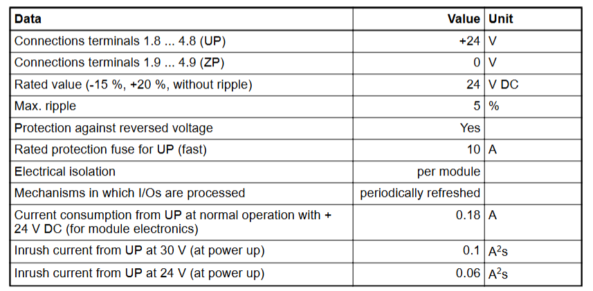
The rated value of the process power supply voltage (UP) is 24 V DC, with an allowable fluctuation range of -15% to+20% and a maximum ripple of 5%.
Power reverse protection: equipped.
Rated protection fuse (fast): 10A.
Current consumed from UP during normal operation: 0.18 A; surge current of 0.1 A when starting a 30 V power supply (lasting for 2 seconds); Surge current of 0.06 A (lasting for 2 seconds) when starting the 24V power supply.
Installation and cooling
Installation position: Horizontal or vertical installation (the maximum working temperature drops to+40 ° C when installed vertically).
Cooling method: Natural convection, cable trays or other components inside the switchgear cabinet must not obstruct cooling.
Allowable values for power interruption (in accordance with EN 61131-2)
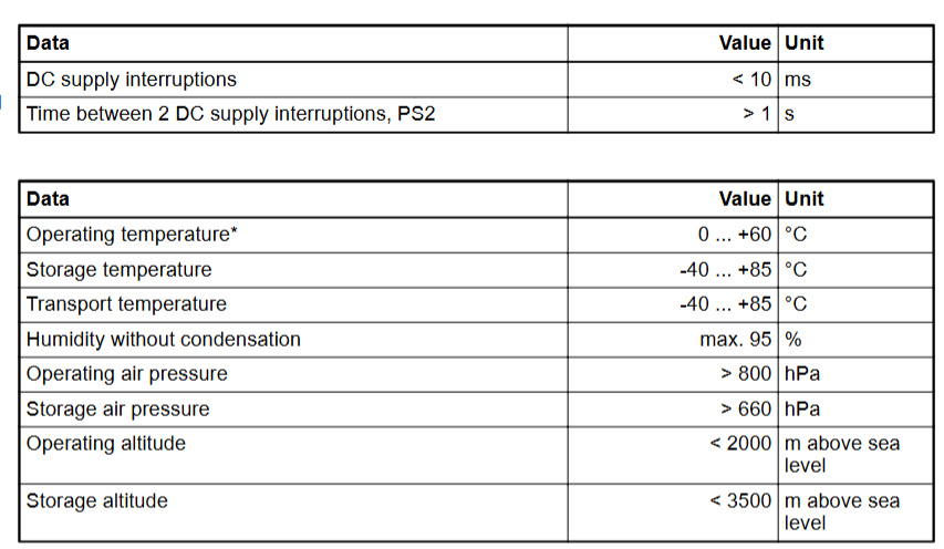
DC power interruption:<10 ms.
The time interval between two DC power interruptions (PS2):>1 second.
Environmental condition
Working temperature: 0 ..+60 ° C (DI581-S-XC supports a wider range in special versions).
Storage and transportation temperature: -40 degrees Celsius ...+85 ° C.
Humidity without condensation: maximum 95%.
Working pressure:>800 hPa; Storage pressure:>660 hPa.
Working altitude:<2000 m; Storage altitude:<3500 m.
Mechanical properties
Protection level: IP 20.
The shell complies with UL 94 standard.
Vibration resistance (compliant with EN 61131-2, three-axis): 2 3.5 mm at 15 Hz; 1 g at 15... 150 Hz.
Impact test (three-axis): 11 ms half sine wave 15 g.
Mean Time Between Failures (MTBF): 102 years.
Technical parameters for secure digital input
Number of input channels per module: 16.
Installation and environmental precautions
Environmental adaptation
Ensure that the working environment of the module meets the parameter requirements: temperature (e.g. DI581-S conventional type is 0~+60 ° C, extreme type DI581-S-XC is -40~+70 ° C), humidity (maximum 95% non condensing), altitude (most modules<2000m), avoid corrosive gases, severe vibrations (in accordance with EN 61131-2 standard), and strong electromagnetic interference.
When installing some modules vertically (such as DI581-S), they need to be downgraded (with a maximum temperature of+40 ° C) to ensure that natural convection cooling is not hindered by cable trays or other components.
Mechanical Installation
Installed with 35mm DIN rails (7.5mm or 15mm depth), the tightening torque meets the requirements (such as DI581-S with 1.2 Nm) to avoid loosening and poor contact.
The module protection level is mostly IP20 and needs to be installed in a closed control cabinet to prevent direct contact with dust and liquids.
Precautions for Electrical Connections
Power Supply and Voltage
The power supply must comply with PELV/SELV specifications (such as DI581-S 24V DC power supply fluctuation range -15%~+20%, ripple ≤ 5%), avoid overvoltage (such as DI581-S can withstand up to 30V DC) or reverse connection (most modules have reverse connection protection, but caution is still needed).
When configuring redundant power supplies, ensure that the switching time between the two power supplies is less than 10ms (in accordance with EN 61131-2) to avoid module restarts or data loss.
Wiring specifications
Signal cables and power cables should be wired separately with a spacing of ≥ 10cm. The shielding layer should be grounded at one end to reduce electromagnetic interference (such as the RS-232/485 communication line of CI853, which needs to be shielded).
The terminal wiring of digital input/output modules (such as DI581-S) needs to distinguish between positive and negative signals (UP/ZP) to avoid short circuits (although the module has short circuit protection, it may affect other channels).
Configuration and operation precautions
Software configuration
Use official tools such as Control Builder and Automation Builder to configure and ensure firmware version is compatible with the module (e.g. AC500 CPU firmware updates need to be done through an SD card or tool to avoid firmware damage caused by power outages).
Redundancy configuration (such as module redundancy in CI853) requires enabling corresponding parameters, verifying the normal switching function before putting it into operation.
Protocol and Communication
The communication module (such as CI853 supporting MODBUS RTU, COMLI) needs to match the protocol parameters of the slave device (baud rate, parity check, etc.), and the DriveBus of CI858 needs to pay attention to the bus topology (multiple drives require NDBU branch units).
Hot plugging operations are only performed when the module is supported (such as CI853, CI858). Before plugging, ensure that there are no data transmission peaks to avoid communication interruptions.
Safety and maintenance precautions
Special requirements for security modules
The safety input module (such as DI581-S) needs to perform regular self checks (such as program flow control, RAM/CPU diagnostics) to ensure compliance with SIL certification requirements and prohibit bypassing safety function configurations.
Extreme environment modules (such as DI581-S-XC) need to be derated when the temperature is greater than 60 ° C (such as when the number of activated input channels is ≤ 50%) to avoid overheating damage.
Battery and data backup
CPU modules with batteries (such as AC500) need to be regularly checked for battery level (through function blocks or tools). When the battery level is ≤ 20%, they should be replaced in a timely manner. During replacement, the module should be powered to prevent loss of retention data.
Important data (such as the retain variable) is recommended to be backed up regularly through an SD card (using the pms_ram_deport function block for AC500 v3) to avoid data loss caused by battery failure.
Fault handling
When the module reports an error, priority should be given to checking the LED indicator lights (such as the channel LED of DI581-S and the fault LED of CI853), and troubleshooting wiring, power, or configuration issues should be carried out in conjunction with the manual. Blindly replacing the module is prohibited.
When modules involving safety circuits (such as DI581-S) fail, they need to be shut down according to safety procedures, and after troubleshooting, they can be reset using tools. Forced operation is prohibited.
Terminals for channels I0 to I7: 2.0 .. 2.7; Terminals for channels I8 to I15: 4.0 4.7.
All input reference potential terminals (negative pole of process power supply voltage, signal name ZP): 1.9... 4.9.
Electrical isolation from other parts of the module (I/O bus): available.
Input type (compliant with EN 61131-2): Type 1.
Input delay (0 ➔ 1 or 1 ➔ 0): configurable, 1 .. 500 ms。
Input signal indication: Each channel has a yellow LED, and when the input signal is high (signal 1), the LED lights up.
Signal voltage
Input signal voltage: 24 V DC.
Signal 0: -3 .. +5 V。
Undefined signal:>+5 .. < +15 V。
Signal 1:+15 .. +30 V。
Input current per channel
When the input voltage is+24 V: typical 7 mA.
When the input voltage is+5 V:>1 mA.
When the input voltage is+15 V:>4 mA.
When the input voltage is+30 V:<8 mA.
Installation and environmental precautions
Environmental adaptation
Ensure that the working environment of the module meets the parameter requirements: temperature (e.g. DI581-S conventional type is 0~+60 ° C, extreme type DI581-S-XC is -40~+70 ° C), humidity (maximum 95% non condensing), altitude (most modules<2000m), avoid corrosive gases, severe vibrations (in accordance with EN 61131-2 standard), and strong electromagnetic interference.
When installing some modules vertically (such as DI581-S), they need to be downgraded (with a maximum temperature of+40 ° C) to ensure that natural convection cooling is not hindered by cable trays or other components.
Mechanical Installation
Installed with 35mm DIN rails (7.5mm or 15mm depth), the tightening torque meets the requirements (such as DI581-S with 1.2 Nm) to avoid loosening and poor contact.
The module protection level is mostly IP20 and needs to be installed in a closed control cabinet to prevent direct contact with dust and liquids.
Precautions for Electrical Connections
Power Supply and Voltage
The power supply must comply with PELV/SELV specifications (such as DI581-S 24V DC power supply fluctuation range -15%~+20%, ripple ≤ 5%), avoid overvoltage (such as DI581-S can withstand up to 30V DC) or reverse connection (most modules have reverse connection protection, but caution is still needed).
When configuring redundant power supplies, ensure that the switching time between the two power supplies is less than 10ms (in accordance with EN 61131-2) to avoid module restarts or data loss.
Wiring specifications
Signal cables and power cables should be wired separately with a spacing of ≥ 10cm. The shielding layer should be grounded at one end to reduce electromagnetic interference (such as the RS-232/485 communication line of CI853, which needs to be shielded).
The terminal wiring of digital input/output modules (such as DI581-S) needs to distinguish between positive and negative signals (UP/ZP) to avoid short circuits (although the module has short circuit protection, it may affect other channels).
Configuration and operation precautions
Software configuration
Use official tools such as Control Builder and Automation Builder to configure and ensure firmware version is compatible with the module (e.g. AC500 CPU firmware updates need to be done through an SD card or tool to avoid firmware damage caused by power outages).
Redundancy configuration (such as module redundancy in CI853) requires enabling corresponding parameters, verifying the normal switching function before putting it into operation.
Protocol and Communication
The communication module (such as CI853 supporting MODBUS RTU, COMLI) needs to match the protocol parameters of the slave device (baud rate, parity check, etc.), and the DriveBus of CI858 needs to pay attention to the bus topology (multiple drives require NDBU branch units).
Hot plugging operations are only performed when the module is supported (such as CI853, CI858). Before plugging, ensure that there are no data transmission peaks to avoid communication interruptions.
Safety and maintenance precautions
Special requirements for security modules
The safety input module (such as DI581-S) needs to perform regular self checks (such as program flow control, RAM/CPU diagnostics) to ensure compliance with SIL certification requirements and prohibit bypassing safety function configurations.
Extreme environment modules (such as DI581-S-XC) need to be derated when the temperature is greater than 60 ° C (such as when the number of activated input channels is ≤ 50%) to avoid overheating damage.
Battery and data backup
CPU modules with batteries (such as AC500) need to be regularly checked for battery level (through function blocks or tools). When the battery level is ≤ 20%, they should be replaced in a timely manner. During replacement, the module should be powered to prevent loss of retention data.
Important data (such as the retain variable) is recommended to be backed up regularly through an SD card (using the pms_ram_deport function block for AC500 v3) to avoid data loss caused by battery failure.
Fault handling
When the module reports an error, priority should be given to checking the LED indicator lights (such as the channel LED of DI581-S and the fault LED of CI853), and troubleshooting wiring, power, or configuration issues should be carried out in conjunction with the manual. Blindly replacing the module is prohibited.
When modules involving safety circuits (such as DI581-S) fail, they need to be shut down according to safety procedures, and after troubleshooting, they can be reset using tools. Forced operation is prohibited.
- YOKOGAWA
- Reliance
- ADVANCED
- SEW
- ProSoft
- WATLOW
- Kongsberg
- FANUC
- VSD
- DCS
- PLC
- man-machine
- Covid-19
- Energy and Gender
- Energy Access
- Renewable Integration
- Energy Subsidies
- Energy and Water
- Net zero emission
- Energy Security
- Critical Minerals
- A-B
- petroleum
- Mine scale
- Sewage treatment
- cement
- architecture
- Industrial information
- New energy
- Automobile market
- electricity
- Construction site
- HIMA
- ABB
- Rockwell
- Schneider Modicon
- Siemens
- xYCOM
- Yaskawa
- Woodward
- BOSCH Rexroth
- MOOG
- General Electric
- American NI
- Rolls-Royce
- CTI
- Honeywell
- EMERSON
- MAN
- GE
- TRICONEX
- Control Wave
- ALSTOM
- AMAT
- STUDER
- KONGSBERG
- MOTOROLA
- DANAHER MOTION
- Bentley
- Galil
- EATON
- MOLEX
- Triconex
- DEIF
- B&W
- ZYGO
- Aerotech
- DANFOSS
- KOLLMORGEN
- Beijer
- Endress+Hauser
- schneider
- Foxboro
- KB
- REXROTH
- YAMAHA
- Johnson
- Westinghouse
- WAGO
- TOSHIBA
- TEKTRONIX
- BENDER
- BMCM
- SMC
- HITACHI
- HIRSCHMANN
- XP POWER
- Baldor
- Meggitt
- SHINKAWA
- Other Brands
- UniOP
- KUKA
- IBA
- Beckhoff
-
ADLINK PCI-8134 - 51-12403-0B20 PCB Board Motion Controller Card
-
ADLINK LPCI-3488A - PCI Card 51-12801-0A30 Low Profile IEEE-488 GPIB Card
-
ADLINK NUPRO-900A - industrial computer motherboard Single Board Computer
-
ADLINK cPCI-6840V - industrial control motherboard CompactPCI SBC
-
ADLINK M-342 - industrial motherboard ATX Mainboard
-
ADLINK NUPRO-935A/LV - industrial control motherboard
-
ADLINK cPCI-3538 - CompactPCI Async Serial Communications Module
-
ADLINK PCI-1610 - Card 4-Port RS-232 PCI Serial Communication Card
-
ADLINK HSL-DI32-DB-N - Distributed I/O Module 32-CH Digital Input
-
ADLINK CPCI-6860A - motherboard E7501 CompactPCI Single Board Computer
-
ADLINK PCI-8134A - 4-Axis Motion Control Card PCB Board
-
ADLINK EURESYS LINK - grabbers Video Capture Card Frame Grabber
-
ADLINK NuPRO-965DV - motherboard Industrial Control Board
-
Thermo Fisher Scientific 80100-60500 - 80000-61010R 80000-21000R 80000-60457 Spectrum System Controller ADLINK Components
-
ADLINK PCI-7296 - IO card High Density 96-CH Opto-Isolated DIO Card
-
ADLINK MXC-6322D - Matrix Industrial Computer Fanless Embedded PC
-
ADLINK DIN-825-GP4 - connector board Terminal Block Interface
-
ADLINK AMP-208C - Motion Control Card DSP-based 8-axis
-
ADLINK PCIe-GIE72 - 51-18531-0A10 2-CH GigE Vision Frame Grabber PoE+ Card
-
ADLINK PXIS-3320 - PXI/PXIe Chassis 15-slot 6U PXI/CompactPCI SEM-I-1518=9N41
-
ADLINK MI-965 - Industrial CPU Motherboard
-
ADLINK M-302 - Industrial control motherboard
-
ADLINK PCI-6308V - 51-12202-0A50 Isolated Analog Output Card PCB-I-E-1813=ZA03
-
ADLINK NUPRO-935A - Industrial Mother Board CPU Board
-
ADLINK PCI-7434 - PLOTECH Digital Output Card PCB-I-E-1182=6EX2
-
ADLINK PCI-7432 - 64 Channel Isolated Digital I/O PCI CARD
-
ADLINK NUPRO-935A/DV - 51-41802-0A10 motherboard Industrial Control Board
-
ADLINK PCIe-GIE72 - 51-18531-0A10 2-CH GigE Vision Frame Grabber PoE+ Card
-
ADLINK HSL-DI16DO16-M-NN - HSL-DI16DO16-M-NN(G)-0280 Discrete I/O Module Distributed I/O
-
ADLINK cPCI-6760D / cPCI-6840V - cPCI Single Board Computer Industrial Motherboard
-
ADLINK NuPRO-A301 - Motherboard IPC Motherboard
-
ADLINK NuPRO-935A/LV - motherboard Industrial Control Board
-
ADLINK NUPRO-E320LV - motherboard Industrial Control Board
-
ADLINK NuPRO-E42 - Industrial Control Board Motherboard
-
ADLINK M-342 - ATX Motherboard Industrial PC Mainboard
-
ADLINK CPCI-6860 / 6860A - Industrial Control Motherboard CompactPCI SBC
-
ADLINK AmITX-SL-G-Q170/GEHC(EA)-021E - 51-7A104-0A20 Industrial Motherboard w/ DDR4
-
ADLINK NUPRO-852 / NUPRO-852LV - industrial control motherboard
-
ADLINK DAQ-2006-004 - Multi-Function DAQ Cards Data Acquisition
-
ADLINK PCIe-RTV24 - Frame Grabbers Video Capture Cards PCI-e x1 4-CH 120fps
-
ADLINK PCI-8134 - 51-12403-0B20 4-Axis Motion Controller Card
-
ADLINK PCI-8132 - 2-Axis Motion Controller Card
-
ADLINK cBP-6402 - Backplane Passive Backplane
-
ADLINK cPCI-6760D - cPCI Single Board Computer Industrial Control Motherboard
-
ADLINK DIN-825-4PO(G)-0030 - Terminal Board Motion Control Breakout Board
-
ADLINK M-322 - Industrial Motherboard
-
ADLINK ABX-1301 - 51-63808-0A20 Industrial Motherboard
-
ADLINK PCI-7433 - 64-CH Isolated Digital Input Card
-
ADLINK AMP-208C - Motion Control card
-
ADLINK DIN-50S-01 - TECHNOLOGY TERMINAL BLOCK INTERFACE MODULES W/ DIN RAIL
-
ADLINK PCI-8134 - 51-12403-0B20 4-Axis Motion Controller Card
-
ADLINK MXE-201/MSSD64G - Technology Automation Computer Fanless Embedded System
-
ADLINK USB-3488A (G) - USB to GPIB CARD Controller Interface
-
ADLINK cPCI-3720L2 - SBC Single Board Computer PCB AMAT 0190-14599
-
ADLINK PCI-7251 - Relay Output Board Expansion Module
-
ADLINK PCI-8124-C - PCB Board 4-CH Encoder Trigger Card
-
ADLINK HD636 - Industrial Computer Board PCB-I-E-2200=9L32-2 Main Board
-
ADLINK USB-3488A - THERMOTRON INDUSTRIES IEEE 488 CPU INTERFACE WITH USB/GPIB
-
ADLINK MI-965 - motherboard Industrial CPU Board
-
ADLINK LPCIe-7250 - Technology Digital IO card Low Profile PCIe Relay Output
-
ADLINK NuPro-720/SCOPUS - Technology With 256MB Industrial MotherBoard
-
ADLINK NuPR0-840 - industrial control motherboard
-
ADLINK M-342 - Motherboard ATX PC Mainboard
-
ADLINK MI-965 - motherboard Industrial CPU Board
-
ADLINK CPCI-6530V/4402E/M4G - AMAT CPCI-6503VED/4402E/M4-0/SD64G-2550 Universal SBC
-
ADLINK IMB-M43-IRV - Industrial Motherboard ATX PC Board
-
ADLINK 52983 / 58183 - Chroma PXI I/O Input/Output Card + Carrier Adapter
-
ADLINK PXI-3920 - PXI 3U cPCI Industrial Controller w/ RAM SSD Embedded CPU
-
ADLINK NuPRO-842LV/P - motherboard Industrial Control PC Board
-
ADLINK PCI-7442 - 64-Channel Datalogging Acquisition Switch Card
-
ADLINK PCIe-RTV24 - Cadre Agrippeurs Vidéo de Capture Cartes Pci-E x1 4-CH
-
ADLINK ACL-7122A - TECHNOLOGY 51-11004-1A1 CIRCUIT BOARD 96-CH DIO Card
-
ADLINK PCIe-RTV24 - 51-18016-0A20 Image Acquisition Video Capture Card
-
ADLINK AMP-204C - DSP-Based 4-Axis Advanced Pulse-Train Motion Controller
-
ADLINK 52981 / 58183 - Chroma PXI Digital I/O DIO Input/Output Card + Carrier Adapter
-
ADLINK PCI-8102 - motion control card 2-Axis
-
ADLINK NuPRO-E320LV - industrial computer motherboard
-
ADLINK PCI-RTV24 - card Analog Video Capture Frame Grabber
-
ADLINK M-302 - Motherboard P/N: 08GSAQ96501102
-
ADLINK NEON-1020 - Smart camera Industrial Machine Vision
-
ADLINK AMP- 208C - card DSP-based 8-axis Motion Controller
-
ADLINK PCI-9114DG - Multi-Function Daq Card Data Acquisition
-
ADLINK MXC-6322D/BE_FanG) - Matrix PM2-MXC Fanless Embedded Computer
-
ADLINK DIN-825-4P0 - Terminal Board Motion Control Breakout Board
-
ADLINK HPCI-8S4 REV.B2 - Industrial Control Base Plate Passive Backplane
-
ADLINK HSL-DI32-DB-N - Distributed I/O Module 32-CH Digital Input
-
ADLINK NuPRO-935A/DV - industrial control motherboard
-
ADLINK PCI-7442 - Switch card 64-CH Datalogging Acquisition Card
-
ADLINK NuPRO-E42 - motherboard 51-41808-0A30 Industrial Motherboard
-
ADLINK CPCI-3610D/N45/M1G(G)-10B0 - CompactPCI Intel Atom Single Board Computer CPU Board
-
ADLINK LPCI-7250 - GP Output Isolated Digital Input Card PCB 51-12803-0A10
-
ADLINK PCI-7250 - 51-12007-0A40 PCI7250 8-CH Relay Output & 8-CH Isolated DI Card
-
ADLINK STC-1005 - 10.4inch touch panel PC E3845 CPU
-
ADLINK PCI-FIW64 - image card FireWire Frame Grabber
-
ADLINK NuPRO-935A/LV - industrial computer motherboard
-
ADLINK PCI-8164 00B0 - Centralized Motion Controller 4-axis PCB-I-E-1179=6EX2
-
ADLINK ACLD-9137F REV A1 - 51-14006-101 Screw Termination Board
-
ADLINK PCI-7248 - 51-12006-0A40 Control Card Digital I/O
-
ADLINK HPCI-8S4 - Technology Backplane PCB GaSonics 3500 Asher Passive Backplane
-
ADLINK NuPRO-E320LV - Cpu Board 51-41804-0A20 Industrial Motherboard
-
ADLINK HPX-13S4 - device baseboard Passive Backplane
-
ADLINK M-322 - industrial motherboard
-
ADLINK NuPRO-865 REV :3.0 - industrial motherboard
-
ADLINK DIN-68S-01 - Terminal Block Interface Module Cable Connection
-
ADLINK ETX-IM266-C100Z - motherboard ETX CPU Module
-
ADLINK NuPRO-E320LV - motherboard Industrial Control Board
-
ADLINK NuPRO-841 REV:2.0 - motherboard Industrial PC Board
-
ADLINK ETX-AT-N270-18 - N270 Board ASH-EAT-18/S512 ET Mainboard
-
ADLINK PCI-RTV24 - Image capture card Analog Frame Grabber
-
ADLINK PCI-8102 - card 2-Axis Motion Controller
-
ADLINK M-322 - industrial motherboard
-
ADLINK PCI-9114 REV.C2 - acquisition card Multi-Function DAQ
-
ADLINK NuPRO-865 REV :3.0 - industrial motherboard
-
ADLINK DIN-68S-01 - Terminal Block Interface Module Cable Connection
-
ADLINK M-322 - Industrial Motherboard Mainboard
-
ADLINK CPCI-6860A - E7501 dual Xeon CPCI Single Board Computer
-
ADLINK MXC-6301D(G) - Technology Expandable Fanless Embedded Computer i7-3610E
-
ADLINK NuPRO-842LV - 51-41360-0B1 Industrial Motherboard
-
ADLINK PBP-08A7 R1MO - PCB Industrial Computer Backplane Passive Backplane
-
ADLINK PCI-3488 - PCI BOARD IEEE-488 GPIB Controller Card
-
ADLINK NuPRO-935A/LV - Industrial Control Motherboard
-
ADLINK PCI-8134 - TECH 4-AXIS MOTION CONTROLLER 4209NB2039 AT23A
-
ADLINK Karbon 700-X2 - Expanded High-Performance Rugged Edge Computer Windows 10
-
ADLINK PCIe-9852 - ADcard 2-CH 8-Bit 200MS/s Digitizer Card
-
ADLINK ETX-BT-E3815 - Industrial Control Module NO AUDIO 91-71116-E020 CT66
-
ADLINK cPCI-8168-006 - cPCI NulPC Motion Control Board
-
ADLINK NuPRO-E43 - 51-41809-0A30 industrial motherboard
-
ADLINK PCI-8134A - PCB Board Motion Controller Card

K-JIANG

Add: Jimei North Road, Jimei District, Xiamen, Fujian, China
Tell:+86-15305925923