
K-WANG


Danfoss VLT ® Series 3000 series adjustable frequency drive
Danfoss VLT ® Series 3000 series adjustable frequency drive
Core technical specifications
1. Key parameters for power supply and output
Key Explanation of Category Specification Range
Input voltage three-phase 200/230V, 380/400/415V, 440/460/500V (± 10%) in accordance with VDE 0160 standard
Input frequency 50/60Hz adaptive grid frequency
Output voltage 0-100% Input voltage synchronously adjusted with frequency
Output frequency standard 0-120Hz, expandable to 0-500Hz, programmable settings (parameter 200)
Output current (continuous) 2.6A (3002) -130A (3052) varies according to model and voltage level
Output current (intermittent 60s) 3.4A (3002) -195A (3052) to meet short-term heavy load requirements
Power range 1HP (3002) -250HP (3250) corresponds to 0.75kW-185kW
Efficiency 0.96 (100% load) High energy efficiency design
Power factor 0.9/1.0 reduces power grid losses
2. Load and motor adaptation
Load type: Supports constant torque (CT) and variable torque (VT, divided into low/medium/high levels). VT mode is suitable for fan and pump loads, while CT mode is suitable for constant loads such as machine tools and conveyor belts.
Motor protection: Built in electronic thermal relay (ETR), compliant with NEC Class 20 standard, can achieve motor overload protection when parameter 315 is set to "TRIP", and the motor rated current needs to be set in conjunction with parameter 107.
Motor tuning: Parameter 106 (AUTO MOTOR TUNING) supports adaptive motor tuning, automatically optimizing parameters 108-113. During tuning, the motor needs to be unloaded or loaded ≤ 50%.
Installation and wiring specifications
1. Installation environment requirements
Temperature: Operating temperature -10~+40 ℃ (VT mode)/-10~+45 ℃ (CT mode), storage/transportation temperature -25~+65 ℃.
Humidity: Maximum 95% (no condensation), in accordance with DIN 40040 cl. E standard.
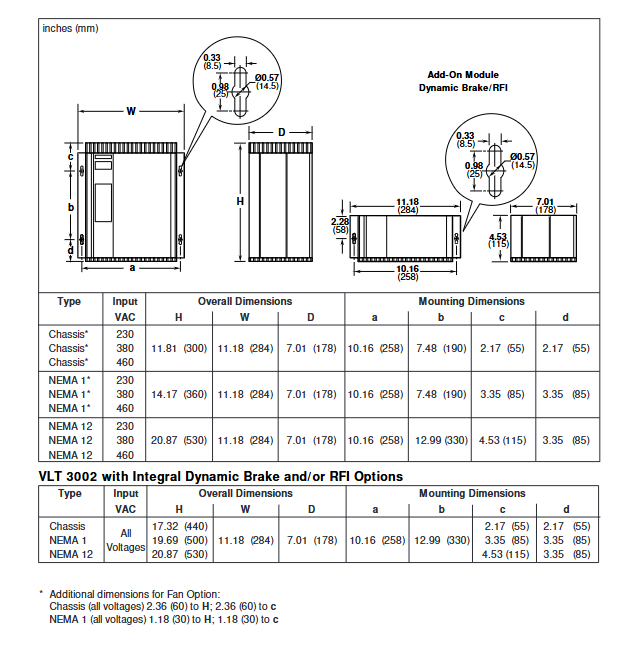
Protection level: Provides four types of enclosure, suitable for different scenarios:
IP00 (open chassis), IP20 (rack mounted), IP21 (NEMA1, splash proof), IP54 (NEMA12, dustproof and waterproof).
Cooling requirements:
Model 3002-3022: Natural convection cooling, requiring a minimum upper and lower heat dissipation space (3.9 inches for IP00/IP21 and 5.9 inches for IP54).
3060-3250 models: forced air cooling, requiring a front space of at least 6 inches, supporting wall/floor mounting (some models include a base).
2. Key requirements for wiring
Cable specifications:
Motor cable: unshielded up to 1000 feet, wire diameter 12-2/0 AWG (depending on model), shielded cable needs to consult Danfoss to confirm the maximum length.
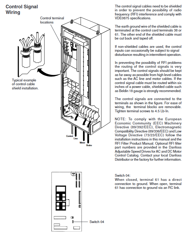
Control line: Shielded cables should be used to avoid parallel laying with power cables (spacing ≥ 6 inches), and one end of the shielding layer should be grounded (terminal 38 or 61).
Terminal torque: Control terminal 4.5 Lb In, power terminal 12-31 Lb In (according to wire diameter).
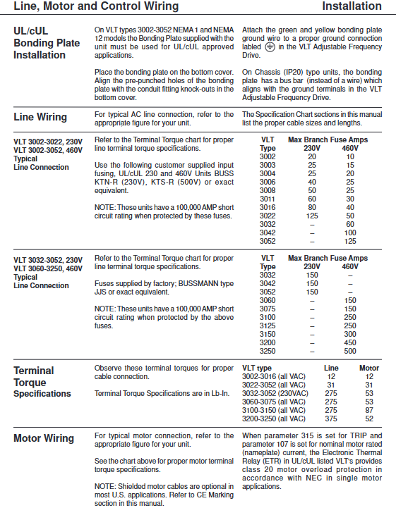
Fuse selection: BUSS KTN-R (230V), KTS-R (500V) or equivalent models are required, with a rated current of 20-500A (depending on the model) and a short-circuit withstand capacity of 100000A.
Grounding requirements: NEMA1/12 models must be equipped with bonding plates and reliably grounded, with grounding resistance in accordance with local regulations.
Core functions and parameter configuration
1. Classification of control functions
(1) Operation mode and torque control
Control modes: open-loop (default), slip compensation (speed accuracy ± 0.5%), closed-loop (PID, speed accuracy ± 0.1%), selected through parameter 101.
Torque mode:
CT mode: constant torque output, suitable for heavy-duty starting; CT COMP mode optimizes the performance of standard induction motors; The four quadrant CT mode supports negative slip compensation (parameter 113).
VT mode: Variable torque output, divided into low/medium/high voltage V/f curves to reduce energy consumption of fans and pumps.
(2) Key operational functions
Slope control: supports three types of slopes, linear/S-curve 1-3 (parameter 214), with a slope time of 0.1-3600 seconds (parameter 215/216), and supports alternative slopes (parameter 217/218) for jogging/emergency stop.
Braking function: DC injection braking (parameters 306-308), braking time 0-60 seconds, braking voltage 0-50V, suitable for rapid shutdown scenarios; Optional dynamic braking module.
Special Features:
Flying Start (parameter 305): Capture the rotating motor and synchronize control, supporting same direction/bidirectional/DC braking before starting.
Jog (parameter 203): Preset Jog frequency (default 10Hz), activated through terminal 29 or panel.
Multi speed control (parameters 205-208): 4 sets of preset speeds, switched through terminals 32/33.
PID closed-loop control: Built in PID regulator (parameters 119-125), supports voltage/current/pulse feedback (parameter 114), suitable for pressure and flow closed-loop control.
2. Core Explanation of Parameter Grouping
Parameter group number range, core function, key parameters
Operation and Display 000-099 Language, Local/Remote, Display Selection 003 (Local/Remote), 004 (Local Reference), 005 (Display Unit)
Load and motor 100-199 motor parameters, tuning, PID 103 (motor power), 106 (adaptive tuning), 114 (feedback type)
Reference and Limitations 200-299 Frequency/Current Limit, Slope 200 (Frequency Range), 209 (Current Limit), 215 (Slope Rise Time)
Function and Timer 300-399 Braking, Reset, Thermal Protection 306 (DC Braking Time), 309 (Reset Mode), 315 (Motor Thermal Protection)
Input and output 400-499 I/O configuration, signal types 402 (startup terminal), 412 (analog input 53), 413 (analog input 60)
Serial communication 500-599 RS-485 configuration 500 (address), 501 (baud rate), 516 (bus reference)
Service and Diagnosis 600-699 Fault, Initialization 602 (Fault Memory), 604 (Initialization), 650 (Model Selection)
Operation and Communication
1. Operation method
Local operation: Controlled by panel buttons, supports start/stop/forward/reverse/jog, parameter 003 is set to "LOCAL", and speed is adjusted through parameter 004 or the panel ± key.
Remote operation:
Digital input: Supports 2-wire (parameter 402=start) and 3-wire (parameter 400=stop, 402=latch start) control.
Analog input: Terminal 53 supports 0-10V voltage signals, and terminal 60 supports 4-20mA current signals (parameter 412/413 configuration).
Serial control: Through RS-485 interface, it supports networking of 31 drivers, enabling parameter reading and writing, speed control, and status feedback.
2. Display function
3-line LCD display, supporting 12 types of operating data: reference value, frequency, current, torque, power, energy consumption, etc.
Dual display function (parameter 605): It can simultaneously display two types of data (such as frequency+current) for real-time monitoring.
Status indication: green LED (power), red LED (alarm), displaying fault code and cause when an alarm occurs.
3. Communication specifications
Interface: RS-485 (terminal 68=positive, 69=negative), supports up to 31 drivers (without repeaters) and 99 drivers (3 repeaters).
Communication parameters: Address 01-99 (parameter 500), baud rate 300/600/1200/2400/4800/9600 (default 9600, parameter 501).
Protocol format: 10 bit data frame (1 start bit+8 data bits+1 stop bit), no checksum, telegram length of 22 bytes, supports control word/status word interaction.
Fault diagnosis and maintenance
1. Common types of faults and their solutions
Fault type, fault code prompt, and handling method
Overvoltage/undervoltage OVER VOLTAGE/ENER VOLTAGE Check the grid voltage and confirm if the braking resistor is normal
Overcurrent OVER CURRENT check for motor short circuit and wiring errors, verify motor current parameters (107)
Ground fault check motor grounding and cable insulation condition
Overheating OVER TEMPClean the cooling channel and check the cooling fan (3060+model)
Motor Overload MOTOR TRIP Check for Load Overload, Extend Slope Time, Adjust Thermal Protection Parameters (315)
Refer to fault REF FAULT to check if the analog input signal (4-20mA/0-10V) is normal
2. Maintenance points
Regular inspection: cable connection tightness, cleanliness of heat dissipation channels, motor thermal protection status (parameter 600).
Parameter backup: Save parameters through parameter 517 (STORE DATA) to avoid accidental loss.
Initialization: There are two initialization methods - parameter 604 (retaining communication/fault parameters) and manual initialization (pressing MENU+DATA+JOG to power on after power off).
Lifespan reminder: The lifespan of electronic components is related to the operating environment. It is recommended to regularly check the capacitor status and shorten the maintenance cycle in heavy load scenarios.
Safety regulations and compliance
Safe operation: After power failure, wait for 4-14 minutes (depending on the model) for the capacitor to discharge. It is forbidden to touch internal components with live electricity; An external emergency stop circuit must be configured to comply with local safety standards.
Compliance certification: CE certification (EMC directive, low voltage directive), EN 55011 Class A (optional Class B), compliant with IEC 801 anti-interference standard.
EMC requirement: Shielded cables should be used for motor cables, and control lines and power cables should be laid separately to avoid electromagnetic interference.
- YOKOGAWA
- Reliance
- ADVANCED
- SEW
- ProSoft
- WATLOW
- Kongsberg
- FANUC
- VSD
- DCS
- PLC
- man-machine
- Covid-19
- Energy and Gender
- Energy Access
- Renewable Integration
- Energy Subsidies
- Energy and Water
- Net zero emission
- Energy Security
- Critical Minerals
- A-B
- petroleum
- Mine scale
- Sewage treatment
- cement
- architecture
- Industrial information
- New energy
- Automobile market
- electricity
- Construction site
- HIMA
- ABB
- Rockwell
- Schneider Modicon
- Siemens
- xYCOM
- Yaskawa
- Woodward
- BOSCH Rexroth
- MOOG
- General Electric
- American NI
- Rolls-Royce
- CTI
- Honeywell
- EMERSON
- MAN
- GE
- TRICONEX
- Control Wave
- ALSTOM
- AMAT
- STUDER
- KONGSBERG
- MOTOROLA
- DANAHER MOTION
- Bentley
- Galil
- EATON
- MOLEX
- Triconex
- DEIF
- B&W
- ZYGO
- Aerotech
- DANFOSS
- KOLLMORGEN
- Beijer
- Endress+Hauser
- schneider
- Foxboro
- KB
- REXROTH
- YAMAHA
- Johnson
- Westinghouse
- WAGO
- TOSHIBA
- TEKTRONIX
- BENDER
- BMCM
- SMC
- HITACHI
- HIRSCHMANN
- XP POWER
- Baldor
- Meggitt
- SHINKAWA
- Other Brands
- UniOP
- KUKA
- IBA
- Beckhoff
-
Basler Electric DECS-250-CN1SN1N Automatic Voltage Regulator for Generator Excitation Control
-
ADLINK CPCI-6860A - 51-31310-OB10 industrial motherboard CompactPCI SBC
-
ADLINK AmITX-SL-G-H110 - 51-7A104-0A30 Mini-ITX Industrial Motherboard
-
ADLINK PXI-2005-003 - CPCI Industrial PC Data Acquisition Card Multi-Function DAQ
-
ADLINK DININ-814M - 51-14032-0A3D SCSI-100P cable connection Interface Terminal Board
-
ADLINK CPCI-3920NA/C2D15/M1G - 3U CompactPCI Intel Core 2 Duo Single Board Computer
-
ADLINK PCIE-8560 - 51-18014-0A20 Communication Card High Speed DAQ
-
ADLINK PCI-C154+ - Motion Control Card 4-axis Motion Controller Board
-
ADLINK PCI-RTV24 - image capture card Analog Video Frame Grabber
-
ADLINK NuPRO-842LV/P - 51-41360-0B30 Industrial Motherboard CPU Board
-
ADLINK cBP-3208/3208R - CPCI Board 3U 8-Slot CompactPCI Backplane
-
ADLINK PCI-8164 - 4-Axis Motion Controller PCI Card 51-12406-0A40
-
ADLINK PCIe-GIE64+ - 4-CH GigE Vision PoE+ Frame Grabber Video Capture Card
-
ADLINK CPCI-6860 / 6860A - CompactPCI Dual Xeon Single Board Computer
-
ADLINK IEC-915GV - REV 1.1 Industrial motherboard CPU Board
-
ADLINK ND-6520 - Technology RS-232 to RS-422RS-485 Converter NuDAM Module
-
ADLINK RTV-24 / PCI-MP4S - 51-12519-1C30 4-Channel Real Time Video Capture Board
-
ADLINK cPCI-6910 / cPCI-6910AM/M1G - cPCI-6910AM/DXL16/M1G/S80G(G)-3120 BOARD CompactPCI SBC
-
ADLINK NUPRO-A40H - Linghua 51-41807-1A30 Industrial Control Computer Motherboard
-
ADLINK USB-3488A - USB to GPIB INTERFACE USB-3488A(G) Controller Module
-
ADLINK PCI-8134A - motion control card 4-Axis Controller Card
-
ADLINK PCI-7432 - Board 32-Channel input / 32-output Isolated Digital I/O PCI Card
-
ADLINK PCI-8134A - 51-12421-0A10 motion controller card tested
-
ADLINK LPCIe-7230 - 32 CH Isolated Input/output Card 2 Interrupts Low Profile PCIe
-
ADLINK NuPRO-E340 - industrial computer motherboard 51-47807-0A30 PICMG 1.3 SHB
-
ADLINK PCI-7434 - High-speed Digital Acquisition Card 64-CH Isolated DO Card
-
ADLINK NuPRO-E330 - 51-41805-0A20 Indsutrial Board SHB Single Board Computer
-
ADLINK PCI-7248 - OPTO-22 48 CHANNEL DIO DIGITAL TTL/DTL I/O 51-12006-0A40 GP
-
ADLINK PCI-8134 - Motion control card 4-Axis Controller Card
-
ADLINK AMP-208C - Movimiento Control Tarjeta 51-12420-1A20 W/Expansión & Breakout
-
ADLINK PCI-8164 - 51-12406-0A40 PCB Board 4-Axis Motion Controller Card
-
ADLINK DIN-68Y-SGII / DIN-68M-J3A - Terminal Board Connector Interface Block
-
ADLINK PCIe-7432 - Technology 51-18402-0A10 PCIe Card With High Input Range
-
ADLINK PCI-8144 / PCI-8144N - Motion control card 4-Axis Stepper Controller Card
-
ADLINK HSL-HUB3/REPEATER - HIGH SPEED LINK EXTENSION MODULES Distributed Hub Module
-
ADLINK ND-6017 - Data Logging + Acquisition 8CH A/D input Mod NuDAM Module
-
ADLINK LPCIe-7250 - data acquisition card Low Profile 8-CH Relay Output Card
-
ADLINK PCI-7432 - I/O card 64-CH Isolated Digital Input Output PCI Card
-
ADLINK IMB-M43H - industrial control computer motherboard Q87 Chip Micro-ATX
-
ADLINK MP-C154 - Motion control Card 4-Axis Motion Controller Board
-
ADLINK PCI-RTV24 - image capture card Video Frame Grabber Card
-
ADLINK PCI-7250 - 8-CH Relay Output & 8-CH Isolated DI Card
-
ADLINK PCI-6308V - 8-CH 12-Bit Isolated Analog Output PCI Card PCB-I-E-1148=6EX2
-
ADLINK PCI-7248 - capture card 48-CH Opto-22 Compatible DIO Card
-
ADLINK HSL-AI16A02-M-VV - Analog Input Output Distributed Module
-
ADLINK NuPRO-A301 - Rev:1.4 NUPRO-A301 PICMG Full-Size Single Board Computer
-
ADLINK PCI-6208V-GL - 8-CH Voltage Analog Output PCI Card
-
ADLINK PCI-8134A - 51-12421-0A10 4-Axis Motion Controller Card
-
ADLINK MNET-S23 - TECHNOLOGY MNET S23 - SERVO DRIVER CONTROL MODULE
-
ADLINK M-342 - ATX I3 I5 I7 Q67 Industrial Motherboard
-
ADLINK NUPRO-780 - Industrial Motherboard CPU Board PICMG SBC
-
ADLINK MP-C154 / MP-C152 - 4-Axis Motion Control Card Pulse-Train Controller
-
ADLINK NuPRO-935A/LV10B0 - Motherboard 51-41802-0A10 GP w/RAM Industrial Control Board
-
ADLINK MP-C154 - Motion control card 4-Axis Motion Controller Mainboard
-
ADLINK PCI-7250 - PCI Acquisition Card 8-CH Relay Output Isolated DI Card
-
ADLINK ACL-7124 - Technology Inc.24 DIO Card Digital Input Output Card
-
ADLINK PCI-8554 A2 - Timer/Counter Data Acquisition Card
-
ADLINK DIN-825-GP4 - Terminal Block Interface Board Breakout Module
-
ADLINK NuPR0-761 - REV:1.1 Industrial motherboard Full-Size PICMG SBC
-
ADLINK MXE-1401/M8G (G) - Matrix Fanless Embedded Computer Industrial PC
-
ADLINK HSL-DI16DO16-UD-NN - Digital 16 Channel I/O Mod Distributed I/O Module
-
ADLINK ND6520 - NUDAM INTELLIGENT DA&C MODULE RS232-RS-422/RS485 CONVERTOR
-
ADLINK NUPRO-761 - REV:1.1 Industrial Motherboard CPU Board
-
ADLINK AMP-208C - Motion Control Card 51-12420-1A20 DSP-based 8-axis
-
ADLINK NuPRO-A301REV 1.4 - with packaging industrial computer motherboard PICMG SBC
-
ADLINK PCM-9112+ - 51-12300-0A2 industrial motherboard Multi-Function DAQ PC/104 Module
-
ADLINK PCM-7250+ - 8-CH Relay Outputs & 8-CH Isolated DI Module PC/104
-
ADLINK PCI-RTV24 - Image capture card Analog Video Frame Grabber
-
ADLINK PCI-8134 - Motion Controller PCI Card 4-Axis Controller Board
-
ADLINK PCI-7432 - Isolated Digital I/O PCI Card
-
ADLINK PCI-8554 A2 - acquisition card Timer/Counter Card
-
ADLINK PCI-8132 - Rev.A2 2-Axis Servo & Stepper Motion Controller Card
-
ADLINK PCI-8132 - Data Acquisition card 2-Axis Motion Controller Card
-
ADLINK EBP-13E4 - 51-46703-0A30 Industrial Backplane Board Passive Backplane
-
ADLINK PCI-800L - Electronic Card Interface Controller Card
-
ADLINK PCIe-GIE72 - 51-18531-0A10 PCB Board GigE Vision Frame Grabber
-
ADLINK DAQ-2010(G)-OOBO - Simultaneous-Sampling Multi-Function DAQ Card
-
ADLINK PCI-9112 - REV.B1 Multifunction DAQ Card Data Acquisition Card
-
ADLINK PCI-7230 - 51-12003-DA60 32-CH Isolated Digital I/O Card
-
ADLINK PCI-7432 - Data Acquisition Card Isolated Digital I/O PCI Card
-
ADLINK ETX-AT-N270-18/LXE - 51-71111-0A20 ETX CPU Module Motherboard
-
ADLINK HSL-DI32-UD-N - DIGITAL INPUT 32 POINTS MODULE Distributed I/O
-
ADLINK AMP-204C - Motion Control card DSP-Based 4-Axis Advanced Controller
-
ADLINK MNET-4XMOG-0050 - Four-axis Motion Controller Distributed Motion Module
-
ADLINK AMP-204C - Motion control card DSP-Based 4-Axis Pulse-Train Controller
-
ADLINK PCI-7442 - Switch card 64-Channel Datalogging & Acquisition Card
-
ADLINK M-302 - Industrial control motherboard ATX PC Board
-
ADLINK NUPRO-852 / NUPRO-852LV - Industrial motherboard Single Board Computer
-
ADLINK PCI-8134 - REV.B1. 4-Axis Motion Controller Card
-
ADLINK PCI-GIE62 + - 51-18502-0A20 2-CH GigE Vision Frame Grabber PoE Card
-
ADLINK PCI-MPG24 - 51-12523-0B20 MPEG4 Card Video Compression Hardware
-
ADLINK HSL-TB32-M-DIN - 32-CH I/O TERMINAL W/ HSL-AI16AO2-M-VV MODULE
-
ADLINK PCI-M114-GL - PCB Ver 2.1 Motion Controller Axis Card
-
ADLINK IMB-M40H - SYM76996H61 motherboard Industrial Computer Mainboard
-
ADLINK NUPRO-A40H - 51-41807-1A20 industrial control motherboard H61 Chip
-
ADLINK PCI-M114-GL - Axis Card Data Acquisition Card PCB VER2.2 Motion Controller
-
ADLINK PCI-8134 - Motion Controller PCI Card 4-Axis Controller Board
-
ADLINK PCI-8102 - Motion control card 2-Axis Servo & Stepper Controller
-
ADLINK NuPRO-841REV:3.0 - motherboard Industrial Control PC Board
-
ADLINK HSL-TB32-U-DIN REV A1 - Breakout Terminal Board Field I/O Module
-
ADLINK AMP-204C - Motion Control card DSP-Based 4-Axis Pulse-Train Controller
-
ADLINK NUPRO-A40H - 51-41807-1A20 industrial control motherboard H61 PC Board
-
ADLINK PCI-6308A / PCI-6308V - 51-12202-0A50 Isolated Analog Output Card
-
ADLINK AMP-204C - DSP-Based 4-Axis Advanced Pulse-Train Motion Controller
-
ADLINK PCI-7434 - Technology 64-Channel Isolated Digital I/O PCI Cards
-
ADLINK CPCI-6840 / CPCI-6840V / PM16/M1G-12G0 - CompactPCI Single Board Computer CPU Module
-
ADLINK PCIE-GIE74 - Motherboard Video Capture Card 51-18531-0A10 Frame Grabber
-
ADLINK NuPRO-E330 - industrial computer equipment motherboard Control Mainboard
-
ADLINK AMP-208C / 51-12420-1A20 - Motion Control Card W/ Expansion & Breakout Board
-
ADLINK HPCI-14S12U - industrial computer baseboard Passive Backplane 14 Slots
-
ADLINK PCI-8164 - 4-Axis Motion Controller PCI Card W/ 1x Cable, 1x Breakout Box
-
ADLINK PCIe-RTV24 - 51-18016-0A20 Image Acquisition Video Capture Card
-
ADLINK M-342 - 5 PCI ATX Motherboard Industrial PC Mainboard
-
ADLINK PCI-FIW64 - 4/2 Channel IEEE1394B Image Capture Card FireWire Frame Grabber
-
ADLINK PCI-7432 - digital IO card 64-CH Isolated Digital Input Output Card
-
ADLINK 51-12001-0C20 - Circuit Board PCI-7200 Data Acquisition Controller Card
-
ADLINK PXI-3920 - PXI 3U cPCI Industrial Controller Embedded System CPU Board
-
ADLINK NuPRO-841REV:2.0 - motherboard Industrial Control PC Board
-
ADLINK NuPro-E330 - 51-41805-0A20 PCB Industrial Control Computer Motherboard
-
ADLINK PCI-RTV24 - Image capture card Analog Video Frame Grabber
-
ADLINK PCI-7442 - Switch card 64-Channel Datalogging & Acquisition Card
-
ADLINK HPX-13S4 - device baseboard Passive Backplane Riser Card
-
ADLINK PCI-9112 REV A.1 - Multi Function DA&C Board Data Acquisition Card
-
ADLINK PCI-7248 - 51-12006-0A40 Card Control 48-CH Digital I/O Module
-
ADLINK CPCI-6860 / 6860A - motherboard CompactPCI Dual Xeon Single Board Computer
-
ADLINK DPAC-3020-11(G) - Embedded PC Automation Controller Machine Control Board
-
ADLINK NuPRO-841 REV:1.0 - industrial control motherboard CPU Board
-
ADLINK MNET-4XMOG-0050 - Four-axis Motion Controller MNET Motion Control Card

K-JIANG

Add: Jimei North Road, Jimei District, Xiamen, Fujian, China
Tell:+86-15305925923