
K-WANG


Rockwell Automation SLC 500 Series Programmable Logic Controller
Rockwell Automation SLC 500 Series Programmable Logic Controller
Processor file structure and address system
1. Core file types and characteristics
Example of file type identification, purpose, element structure, address format
Output file O0: Store external output signal 1 word/element (16 bits) O: 3/15 (slot 3, bit 15), O: 5.1 (slot 5, word 1)
Input file I1: Store external input signal 1 word/element (16 bits) I: 7/8 (slot 7, bit 8), I: 2.1/3 (slot 2, word 1, bit 3)
Status file S2: Storage system status and status bit 1 word/element (16 bits) S: 1/15 (element 1, bit 15, first scan bit)
Bit file B3: Relay logic, shift register 1 word/element (16 bits), maximum 256 elements B3:3/14 (element 3, bit 14), B3/62 (62nd bit in the file)
Timer file T4: Timing control (TON/TOF/RTO) 3 words/element (status+preset+accumulation) T4:0/EN (enable bit), T4:0. PRE (preset value)
Counter file C5: Count Control (CTU/CTD/HSC) 3 words/element (Status+Preset+Accumulate) C5:0/CU (Add Count Enable), C5:0.ACC (Accumulate Value)
Control file R6: Shift/sequence/ASCII instruction controls 3 words/element (status+length+position) R6:2/LEN (length value), R6:2.POS (position value)
Integer file N7: Integer data storage and operation 1 word/element (16 bits) N7:2 (element 2), N10:36 (custom integer file 10, element 36)
Floating point file F8: Floating point data storage and operation 2 words/element (32-bit) F8:2 (element 2), only supported by SLC 5/03 and above
2. Address coding rules
Common format: File identifier: Slot number Font size/bit number (e.g. T4:0.1/0 represents timer file 4, element 0, character 1, bit 0)
Simplification rule: When the font size is 0, it can be omitted (e.g. O: 5/0=O: 5.0/0)
Extended configuration: File 9-255 can be customized through programming as bit/timer/counter/integer/floating point and other types to meet the needs of extended storage
Detailed classification and functions of core instructions
1. Basic instructions (13)
The core is used for bit operations, timing, and counting, and is the most fundamental logical unit in industrial control:
Bit operation instructions: XIC (check closed), XIO (check open), OTE (output Energize), OTL (output latch), OTU (output unlock), OSR (rising edge single trigger)
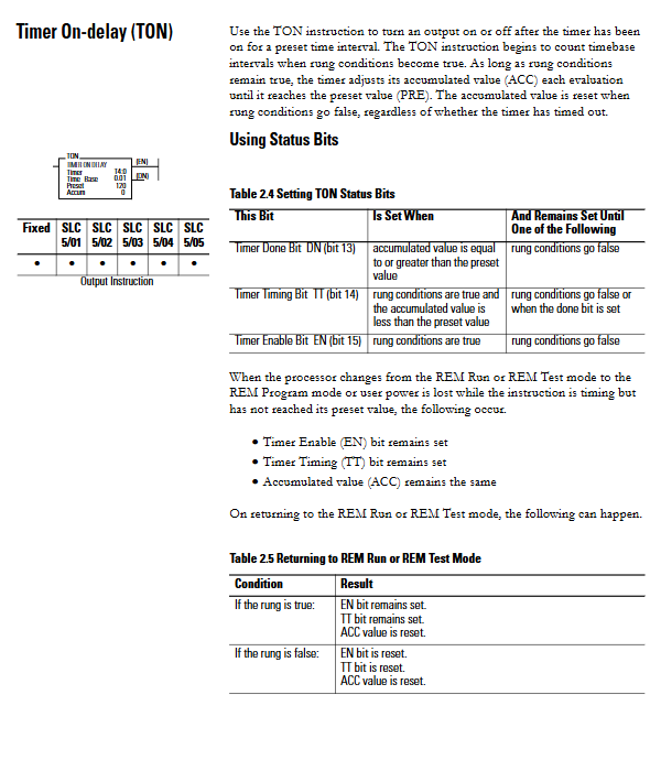
Timing instructions: TON (power on delay), TOF (power off delay), RTO (hold type timing), support 0.01 second time base, preset/accumulated value range 0-32767
Counting instructions: CTU (up counting), CTD (down counting), HSC (high-speed counting, only fixed controller 24VDC input), counting range -32768 to 32767
Reset instruction: RES (Reset timer/counter, not available for TOF instruction)
2. Comparison instructions (8 items)
Used for data logic judgment and controlling program flow:
Command function supports parameter types
EQU is equal to comparing source A (address) and source B (address/constant)
NEQ does not equal comparing source A (address) and source B (address/constant)
LES/LEQ/GRT/GEQ less than/equal to/greater than/equal to source A (address), source B (address/constant)
MEQ mask is equal to the comparison source, mask (hexadecimal/address), and reference value
LIM range testing low limit, test value, high limit (address/constant)
3. Mathematical Instructions (22 pieces)
Covering arithmetic operations, data scaling, trigonometric functions, etc., supporting integer/floating-point operations:
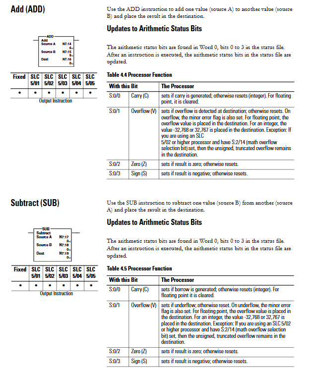
Basic operations: ADD (addition), SUB (subtraction), MUL (multiplication), DIV (division), DDV (double word division)
Data processing: CLR (reset), SQR (square root), ABS (absolute value), NEG (reverse), SWP (byte swapping)
Scaling instructions: SCP (with parameter scaling), SCL (data scaling), supporting 4-20mA/0-10V analog signal conversion
Advanced operations: RMP (slope generation), CPT (expression calculation), ASN/ACS/ATN (inverse trigonometric function), etc., only SLC 5/03 and above support
4. Data processing instructions (20 pieces)
Used for data format conversion, transmission, and storage:
Format conversion: TOD (integer to BCD), FRD (BCD to integer), DEG (radians to angles), RAD (angles to radians)
Encoding and decoding: DCD (4-bit decoding with 16 options), ENC (16 bit encoding with 4 bits)
File operation: COP (file copy), FLL (file fill), maximum length 128 words (1 word/element) or 42 elements (3 words/element)
Data transmission: MOV (move), MVM (mask move), AND/OR/XOR/NOT (bit logic operation)
Stack operations: FFL/FFU (FIFO in/out), LFL/LFU (LIFO in/out), supporting 128 word stack
5. Program flow instructions (10 items)
Control program execution sequence and optimize scanning efficiency:
Jump command: JMP (jump)+LBL (tag), supports forward and backward jumps, avoids dead loop triggering watchdog timeout
Subroutine instructions: JSR (call)+SBR (subroutine)+RET (return), nesting depth: fixed/SLC 5/01 at level 4, others at level 8
Control area instruction: MCR (main control reset), turn off non hold output in designated area
Debugging instructions: TND (Temporary End), SUS (Pause), used for program debugging and fault location
I/O refresh instructions: IIM (immediate input mask), IOM (immediate output mask), REF (I/O refresh), interrupt scan to update I/O
6. Apply specific instructions (10)
Design for specific industrial scenarios:
Shift instruction: BSL (left shift), BSR (right shift), supports up to 2048 bit array
Sequencer instructions: SQO (sequence output), SQC (sequence comparison), SQL (sequence loading), control sequential machine operations
Timestamp instruction: RHC (read high-speed clock), TDF (calculate time difference), 10 μ s accuracy, supports event timing
Diagnostic instructions: FBC (File Bit Comparison), DDT (Diagnostic Detection), monitoring equipment faults, recording unmatched bits
Verification instruction: RPC (Read Program Checksum), verifies program integrity
7. Block transfer instructions (2)
Used for remote I/O device data transmission (only supported by SLC 5/03 and above):
Command function key parameter error code
BTR reads data files, buffer files (M0/M1), control block-6 (illegal length), -9 (timeout), etc. from remote devices
BTW writes data files, buffer files (M0/M1), control block-7 (communication error), -11 (invalid device), etc. to remote devices
Transmission capacity: up to 32 block transmission buffers, 1-64 words per transmission, supporting RIO links
8. PID instruction
Used for process control of temperature, pressure, liquid level, etc.:
Control modes: Timer mode (custom update rate), STI interrupt mode (synchronized with STI interval)
Core parameters: proportional gain (Kc), reset time (Ti), rate time (Td), dead zone (DB), output limit (CVL/CVH)
Input and output: process variables (PV), set values (SP), control variables (CV), support 0-16383 scaling range
Functional features: anti integral saturation, manual/automatic switching, Feed Forward/Bias offset
Instruction Execution and Status Bit Mechanism
1. Core status bit (stored in S: 0/0-3)
Status bit identification function
When the carry bit S is generated by arithmetic operation 0/0, set it to 1
Overflow bit S: When the result of 0/1 exceeds the data range, set it to 1 (such as integer operation>32767)
Zero position S: When the result of the 0/2 operation is 0, set it to 1
When the sign bit S is 0/3 and the result is negative, set it to 1 (the highest bit is 1)
2. Dedicated status bit
Command universal bits: EN (enable, set to 1 when run is true), DN (complete, set to 1 when operation ends), ER (set to 1 when error, exception)
Timer specific: TT (during timing, accumulate<preset time set to 1)
Counter specific: CU (up count enable), CD (down count enable), OV (overflow), UN (underflow)
3. Error handling mechanism
Overflow trap bit: S: 5/0, detected mathematical overflow or zero division set to 1, must be reset through OTU instruction to avoid major errors (code 0020)
Block transmission error: Control block word 2 to store error codes (-6 to -12), such as -9 indicating transmission timeout
Fault clearing: supports automatic clearing (such as power on errors) and manual clearing (such as program download errors)
Programming Limitations and Compatibility
1. Compatibility of processor models
Instruction type support model restriction explanation
The entire HSC series of basic instructions only supports fixed controller 24VDC input
Advanced Mathematical Instructions (SCP/RPM/CPT, etc.) SLC 5/03 and above require OS302/OS401/OS501 and above firmware
The block transfer instruction SLC 5/03 (OS302) and above requires RSLogix 500 v4.10+
The PID instruction series STI mode only supports SLC 5/02 and above
2. Operational restrictions
Address range: bit numbers 0-15, element numbers 0-255, maximum file length 2048 bits (bit array)
Scanning requirement: The timer command should be scanned every 2.5 seconds to avoid timing errors; HSC instructions need to run unconditionally to avoid counting loss
Regional restriction: prohibit JMP commands from jumping into the MCR area; MCR area cannot be nested
Data type: Floating point operations only support SLC 5/03 and above, negative numbers are stored as binary complement
Troubleshooting and Maintenance
1. Common types of faults
Power on error: If the power supply is abnormal or the module is not recognized, the hardware connection needs to be checked
Running errors: such as instruction parameter errors, address out of bounds, located through error logs
I/O errors: such as I/O module failures or wiring errors, detected through the I/O table error flag (A261)
Program errors: such as nested subroutine overflow, MCR instruction mismatch, compile time prompt
2. Maintenance points
Firmware upgrade: OS300/OS400/OS500 series firmware supports feature expansion and needs to match CX Programmer version
Battery maintenance: Key data (DM/EM/HR) are backed up by the battery, and the battery status needs to be checked regularly
Data backup: backing up program, parameter, and annotation data through memory card execution
Fault log: The system can store up to 20 error records, including error codes and occurrence times
- YOKOGAWA
- Reliance
- ADVANCED
- SEW
- ProSoft
- WATLOW
- Kongsberg
- FANUC
- VSD
- DCS
- PLC
- man-machine
- Covid-19
- Energy and Gender
- Energy Access
- Renewable Integration
- Energy Subsidies
- Energy and Water
- Net zero emission
- Energy Security
- Critical Minerals
- A-B
- petroleum
- Mine scale
- Sewage treatment
- cement
- architecture
- Industrial information
- New energy
- Automobile market
- electricity
- Construction site
- HIMA
- ABB
- Rockwell
- Schneider Modicon
- Siemens
- xYCOM
- Yaskawa
- Woodward
- BOSCH Rexroth
- MOOG
- General Electric
- American NI
- Rolls-Royce
- CTI
- Honeywell
- EMERSON
- MAN
- GE
- TRICONEX
- Control Wave
- ALSTOM
- AMAT
- STUDER
- KONGSBERG
- MOTOROLA
- DANAHER MOTION
- Bentley
- Galil
- EATON
- MOLEX
- Triconex
- DEIF
- B&W
- ZYGO
- Aerotech
- DANFOSS
- KOLLMORGEN
- Beijer
- Endress+Hauser
- schneider
- Foxboro
- KB
- REXROTH
- YAMAHA
- Johnson
- Westinghouse
- WAGO
- TOSHIBA
- TEKTRONIX
- BENDER
- BMCM
- SMC
- HITACHI
- HIRSCHMANN
- XP POWER
- Baldor
- Meggitt
- SHINKAWA
- Other Brands
- UniOP
- KUKA
- IBA
- Beckhoff
-
Basler Electric DECS-250-CN1SN1N Automatic Voltage Regulator for Generator Excitation Control
-
ADLINK CPCI-6860A - 51-31310-OB10 industrial motherboard CompactPCI SBC
-
ADLINK AmITX-SL-G-H110 - 51-7A104-0A30 Mini-ITX Industrial Motherboard
-
ADLINK PXI-2005-003 - CPCI Industrial PC Data Acquisition Card Multi-Function DAQ
-
ADLINK DININ-814M - 51-14032-0A3D SCSI-100P cable connection Interface Terminal Board
-
ADLINK CPCI-3920NA/C2D15/M1G - 3U CompactPCI Intel Core 2 Duo Single Board Computer
-
ADLINK PCIE-8560 - 51-18014-0A20 Communication Card High Speed DAQ
-
ADLINK PCI-C154+ - Motion Control Card 4-axis Motion Controller Board
-
ADLINK PCI-RTV24 - image capture card Analog Video Frame Grabber
-
ADLINK NuPRO-842LV/P - 51-41360-0B30 Industrial Motherboard CPU Board
-
ADLINK cBP-3208/3208R - CPCI Board 3U 8-Slot CompactPCI Backplane
-
ADLINK PCI-8164 - 4-Axis Motion Controller PCI Card 51-12406-0A40
-
ADLINK PCIe-GIE64+ - 4-CH GigE Vision PoE+ Frame Grabber Video Capture Card
-
ADLINK CPCI-6860 / 6860A - CompactPCI Dual Xeon Single Board Computer
-
ADLINK IEC-915GV - REV 1.1 Industrial motherboard CPU Board
-
ADLINK ND-6520 - Technology RS-232 to RS-422RS-485 Converter NuDAM Module
-
ADLINK RTV-24 / PCI-MP4S - 51-12519-1C30 4-Channel Real Time Video Capture Board
-
ADLINK cPCI-6910 / cPCI-6910AM/M1G - cPCI-6910AM/DXL16/M1G/S80G(G)-3120 BOARD CompactPCI SBC
-
ADLINK NUPRO-A40H - Linghua 51-41807-1A30 Industrial Control Computer Motherboard
-
ADLINK USB-3488A - USB to GPIB INTERFACE USB-3488A(G) Controller Module
-
ADLINK PCI-8134A - motion control card 4-Axis Controller Card
-
ADLINK PCI-7432 - Board 32-Channel input / 32-output Isolated Digital I/O PCI Card
-
ADLINK PCI-8134A - 51-12421-0A10 motion controller card tested
-
ADLINK LPCIe-7230 - 32 CH Isolated Input/output Card 2 Interrupts Low Profile PCIe
-
ADLINK NuPRO-E340 - industrial computer motherboard 51-47807-0A30 PICMG 1.3 SHB
-
ADLINK PCI-7434 - High-speed Digital Acquisition Card 64-CH Isolated DO Card
-
ADLINK NuPRO-E330 - 51-41805-0A20 Indsutrial Board SHB Single Board Computer
-
ADLINK PCI-7248 - OPTO-22 48 CHANNEL DIO DIGITAL TTL/DTL I/O 51-12006-0A40 GP
-
ADLINK PCI-8134 - Motion control card 4-Axis Controller Card
-
ADLINK AMP-208C - Movimiento Control Tarjeta 51-12420-1A20 W/Expansión & Breakout
-
ADLINK PCI-8164 - 51-12406-0A40 PCB Board 4-Axis Motion Controller Card
-
ADLINK DIN-68Y-SGII / DIN-68M-J3A - Terminal Board Connector Interface Block
-
ADLINK PCIe-7432 - Technology 51-18402-0A10 PCIe Card With High Input Range
-
ADLINK PCI-8144 / PCI-8144N - Motion control card 4-Axis Stepper Controller Card
-
ADLINK HSL-HUB3/REPEATER - HIGH SPEED LINK EXTENSION MODULES Distributed Hub Module
-
ADLINK ND-6017 - Data Logging + Acquisition 8CH A/D input Mod NuDAM Module
-
ADLINK LPCIe-7250 - data acquisition card Low Profile 8-CH Relay Output Card
-
ADLINK PCI-7432 - I/O card 64-CH Isolated Digital Input Output PCI Card
-
ADLINK IMB-M43H - industrial control computer motherboard Q87 Chip Micro-ATX
-
ADLINK MP-C154 - Motion control Card 4-Axis Motion Controller Board
-
ADLINK PCI-RTV24 - image capture card Video Frame Grabber Card
-
ADLINK PCI-7250 - 8-CH Relay Output & 8-CH Isolated DI Card
-
ADLINK PCI-6308V - 8-CH 12-Bit Isolated Analog Output PCI Card PCB-I-E-1148=6EX2
-
ADLINK PCI-7248 - capture card 48-CH Opto-22 Compatible DIO Card
-
ADLINK HSL-AI16A02-M-VV - Analog Input Output Distributed Module
-
ADLINK NuPRO-A301 - Rev:1.4 NUPRO-A301 PICMG Full-Size Single Board Computer
-
ADLINK PCI-6208V-GL - 8-CH Voltage Analog Output PCI Card
-
ADLINK PCI-8134A - 51-12421-0A10 4-Axis Motion Controller Card
-
ADLINK MNET-S23 - TECHNOLOGY MNET S23 - SERVO DRIVER CONTROL MODULE
-
ADLINK M-342 - ATX I3 I5 I7 Q67 Industrial Motherboard
-
ADLINK NUPRO-780 - Industrial Motherboard CPU Board PICMG SBC
-
ADLINK MP-C154 / MP-C152 - 4-Axis Motion Control Card Pulse-Train Controller
-
ADLINK NuPRO-935A/LV10B0 - Motherboard 51-41802-0A10 GP w/RAM Industrial Control Board
-
ADLINK MP-C154 - Motion control card 4-Axis Motion Controller Mainboard
-
ADLINK PCI-7250 - PCI Acquisition Card 8-CH Relay Output Isolated DI Card
-
ADLINK ACL-7124 - Technology Inc.24 DIO Card Digital Input Output Card
-
ADLINK PCI-8554 A2 - Timer/Counter Data Acquisition Card
-
ADLINK DIN-825-GP4 - Terminal Block Interface Board Breakout Module
-
ADLINK NuPR0-761 - REV:1.1 Industrial motherboard Full-Size PICMG SBC
-
ADLINK MXE-1401/M8G (G) - Matrix Fanless Embedded Computer Industrial PC
-
ADLINK HSL-DI16DO16-UD-NN - Digital 16 Channel I/O Mod Distributed I/O Module
-
ADLINK ND6520 - NUDAM INTELLIGENT DA&C MODULE RS232-RS-422/RS485 CONVERTOR
-
ADLINK NUPRO-761 - REV:1.1 Industrial Motherboard CPU Board
-
ADLINK AMP-208C - Motion Control Card 51-12420-1A20 DSP-based 8-axis
-
ADLINK NuPRO-A301REV 1.4 - with packaging industrial computer motherboard PICMG SBC
-
ADLINK PCM-9112+ - 51-12300-0A2 industrial motherboard Multi-Function DAQ PC/104 Module
-
ADLINK PCM-7250+ - 8-CH Relay Outputs & 8-CH Isolated DI Module PC/104
-
ADLINK PCI-RTV24 - Image capture card Analog Video Frame Grabber
-
ADLINK PCI-8134 - Motion Controller PCI Card 4-Axis Controller Board
-
ADLINK PCI-7432 - Isolated Digital I/O PCI Card
-
ADLINK PCI-8554 A2 - acquisition card Timer/Counter Card
-
ADLINK PCI-8132 - Rev.A2 2-Axis Servo & Stepper Motion Controller Card
-
ADLINK PCI-8132 - Data Acquisition card 2-Axis Motion Controller Card
-
ADLINK EBP-13E4 - 51-46703-0A30 Industrial Backplane Board Passive Backplane
-
ADLINK PCI-800L - Electronic Card Interface Controller Card
-
ADLINK PCIe-GIE72 - 51-18531-0A10 PCB Board GigE Vision Frame Grabber
-
ADLINK DAQ-2010(G)-OOBO - Simultaneous-Sampling Multi-Function DAQ Card
-
ADLINK PCI-9112 - REV.B1 Multifunction DAQ Card Data Acquisition Card
-
ADLINK PCI-7230 - 51-12003-DA60 32-CH Isolated Digital I/O Card
-
ADLINK PCI-7432 - Data Acquisition Card Isolated Digital I/O PCI Card
-
ADLINK ETX-AT-N270-18/LXE - 51-71111-0A20 ETX CPU Module Motherboard
-
ADLINK HSL-DI32-UD-N - DIGITAL INPUT 32 POINTS MODULE Distributed I/O
-
ADLINK AMP-204C - Motion Control card DSP-Based 4-Axis Advanced Controller
-
ADLINK MNET-4XMOG-0050 - Four-axis Motion Controller Distributed Motion Module
-
ADLINK AMP-204C - Motion control card DSP-Based 4-Axis Pulse-Train Controller
-
ADLINK PCI-7442 - Switch card 64-Channel Datalogging & Acquisition Card
-
ADLINK M-302 - Industrial control motherboard ATX PC Board
-
ADLINK NUPRO-852 / NUPRO-852LV - Industrial motherboard Single Board Computer
-
ADLINK PCI-8134 - REV.B1. 4-Axis Motion Controller Card
-
ADLINK PCI-GIE62 + - 51-18502-0A20 2-CH GigE Vision Frame Grabber PoE Card
-
ADLINK PCI-MPG24 - 51-12523-0B20 MPEG4 Card Video Compression Hardware
-
ADLINK HSL-TB32-M-DIN - 32-CH I/O TERMINAL W/ HSL-AI16AO2-M-VV MODULE
-
ADLINK PCI-M114-GL - PCB Ver 2.1 Motion Controller Axis Card
-
ADLINK IMB-M40H - SYM76996H61 motherboard Industrial Computer Mainboard
-
ADLINK NUPRO-A40H - 51-41807-1A20 industrial control motherboard H61 Chip
-
ADLINK PCI-M114-GL - Axis Card Data Acquisition Card PCB VER2.2 Motion Controller
-
ADLINK PCI-8134 - Motion Controller PCI Card 4-Axis Controller Board
-
ADLINK PCI-8102 - Motion control card 2-Axis Servo & Stepper Controller
-
ADLINK NuPRO-841REV:3.0 - motherboard Industrial Control PC Board
-
ADLINK HSL-TB32-U-DIN REV A1 - Breakout Terminal Board Field I/O Module
-
ADLINK AMP-204C - Motion Control card DSP-Based 4-Axis Pulse-Train Controller
-
ADLINK NUPRO-A40H - 51-41807-1A20 industrial control motherboard H61 PC Board
-
ADLINK PCI-6308A / PCI-6308V - 51-12202-0A50 Isolated Analog Output Card
-
ADLINK AMP-204C - DSP-Based 4-Axis Advanced Pulse-Train Motion Controller
-
ADLINK PCI-7434 - Technology 64-Channel Isolated Digital I/O PCI Cards
-
ADLINK CPCI-6840 / CPCI-6840V / PM16/M1G-12G0 - CompactPCI Single Board Computer CPU Module
-
ADLINK PCIE-GIE74 - Motherboard Video Capture Card 51-18531-0A10 Frame Grabber
-
ADLINK NuPRO-E330 - industrial computer equipment motherboard Control Mainboard
-
ADLINK AMP-208C / 51-12420-1A20 - Motion Control Card W/ Expansion & Breakout Board
-
ADLINK HPCI-14S12U - industrial computer baseboard Passive Backplane 14 Slots
-
ADLINK PCI-8164 - 4-Axis Motion Controller PCI Card W/ 1x Cable, 1x Breakout Box
-
ADLINK PCIe-RTV24 - 51-18016-0A20 Image Acquisition Video Capture Card
-
ADLINK M-342 - 5 PCI ATX Motherboard Industrial PC Mainboard
-
ADLINK PCI-FIW64 - 4/2 Channel IEEE1394B Image Capture Card FireWire Frame Grabber
-
ADLINK PCI-7432 - digital IO card 64-CH Isolated Digital Input Output Card
-
ADLINK 51-12001-0C20 - Circuit Board PCI-7200 Data Acquisition Controller Card
-
ADLINK PXI-3920 - PXI 3U cPCI Industrial Controller Embedded System CPU Board
-
ADLINK NuPRO-841REV:2.0 - motherboard Industrial Control PC Board
-
ADLINK NuPro-E330 - 51-41805-0A20 PCB Industrial Control Computer Motherboard
-
ADLINK PCI-RTV24 - Image capture card Analog Video Frame Grabber
-
ADLINK PCI-7442 - Switch card 64-Channel Datalogging & Acquisition Card
-
ADLINK HPX-13S4 - device baseboard Passive Backplane Riser Card
-
ADLINK PCI-9112 REV A.1 - Multi Function DA&C Board Data Acquisition Card
-
ADLINK PCI-7248 - 51-12006-0A40 Card Control 48-CH Digital I/O Module
-
ADLINK CPCI-6860 / 6860A - motherboard CompactPCI Dual Xeon Single Board Computer
-
ADLINK DPAC-3020-11(G) - Embedded PC Automation Controller Machine Control Board
-
ADLINK NuPRO-841 REV:1.0 - industrial control motherboard CPU Board
-
ADLINK MNET-4XMOG-0050 - Four-axis Motion Controller MNET Motion Control Card

K-JIANG

Add: Jimei North Road, Jimei District, Xiamen, Fujian, China
Tell:+86-15305925923