
K-WANG


EATON FP-5000 microprocessor base panel mounted multifunctional protection relay
EATON FP-5000 microprocessor base panel mounted multifunctional protection relay
Product basic positioning and core features
Core positioning: microprocessor based panel mounted protective relay, designed for ANSI and IEC application scenarios, suitable for main power supply, contact line or feeder protection of medium voltage distribution circuits (up to 69kV). A single device can cover the comprehensive protection requirements of three-phase circuits;
Target users: System engineers, operators, and troubleshooting personnel, providing full process guidance from equipment configuration, operation, to fault analysis;
Compliance certification: Complies with ANSI/IEEE C37.90, IEC 255-3, UL/CUL 1053 and other standards, passes CE, CB, AK certification, electromagnetic compatibility meets EN 61000 series requirements, RoHS compliance;
Core advantages: Multi functional integration (protection/monitoring/control/metering), multi curve adaptation, wide temperature operation (-40~60 ℃), support for remote communication and programming, rich logging and fault analysis capabilities.
Hardware parameters and physical characteristics
(1) Key hardware specifications
Category specific parameters
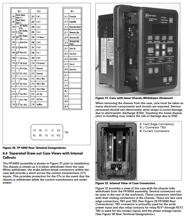
Measurement of input current: 4-channel CT input (5A for FP5000-00 and 1A for FP5100-00), maximum steady-state 2Inom, instantaneous 80-100Inom (1 second); Voltage: 4-channel VT input (0-120VAC line to ground, 0-144VAC overload)
Switching I/O input: 8 passive optical isolation contacts( 40Vdc@2mA ); Output: 7-way relay (2 Form C+5 Form A), contact capacity 30A (0.25 seconds), 5A (continuous)
Local communication interface: RS-232 (DB9); Remote: INCOM FSK, supports MODBUS RTU/IMPACC protocol, baud rate 9600-38400bps
Standard power configuration: 100-120VAC/48-125VDC; Wide width version: 100-240VAC/100-250VDC, interruption tolerance time 83ms-300ms
Memory and backup non-volatile Flash memory, 3V VL2330 rechargeable lithium battery (backup RTC and event logs, backup for 3 months at 25 ℃)
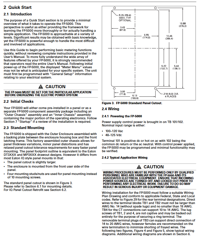
Physical dimensions panel: 165.1 × 254mm (width × height), opening: 174 × 78mm, depth: 177.8mm; weight: shell 2.27kg, pull unit 2.63kg
Protection level panel IP52, shell IP20, vibration/impact resistance meets industrial standards
(2) Display and operation interface
Display module: 4-line x 20 character vacuum fluorescent screen, supports sleep mode (black screen after 15 minutes without operation, wake-up prompt after 5 minutes);
Operation buttons: 15 film buttons (including reset, monitoring, setting, logging, status control and other function buttons), 6 navigation buttons (up and down/up and down/confirm/return);
Status LED: 11 indicator lights (running, circuit breaker opening and closing, phase/ground/other tripping, alarm, pickup, auxiliary, setting/testing mode).
Detailed explanation of core functions
(1) Protection function system
overcurrent protection
Phase overcurrent: 2-level instantaneous overcurrent (50P-1/50P-2), time limited overcurrent (51P), voltage constrained time limited overcurrent (51P2), supporting forward/reverse/bidirectional direction monitoring;
Grounding overcurrent: Independently measure grounding (50X/51X) and residual grounding (50R/51R), each containing 2 levels of instantaneous and 1 level of time limited overcurrent. 50X supports 3 custom curves;
Curve types: 10 standard curves (thermal curve: It/I2t/I4t/Flat; ANSI curve: MOD/VERY/XTRM; IEC curve: IECA/IECB/IECC), with optional instantaneous/delayed/calculated reset modes.
Other protective functions
Voltage protection: Main/auxiliary power undervoltage (27M/27A), overvoltage (59M/59A), neutral line overvoltage (59N), supports triggering of any phase/two-phase/three-phase;
Frequency protection: under frequency (81U), over frequency (81O), threshold 45-65Hz, accuracy ± 0.02Hz;
Unbalance protection: current imbalance (46), voltage imbalance (47), based on the ratio of negative sequence/positive sequence components (2-40%);
Special protection: Circuit breaker failure protection (50BF, supports internal/external/dual triggering), synchronous inspection (25, monitors voltage difference/angle difference/slip), regional interlocking (87B, supports phase/ground/bidirectional interlocking), cold load switching (avoids closing shock).
(2) Monitoring and metering functions
Basic monitoring: three-phase phase/line voltage, three-phase current/zero sequence current, active/reactive/apparent power, power factor (apparent/displacement), system frequency (45-65Hz);
Power quality: 2-15th harmonic components, total harmonic distortion (THD), voltage/current imbalance;
Statistical analysis: current/power demand (fixed/sliding window, 1-60 minutes), extreme value recording (maximum/minimum value+timestamp), energy metering (positive and negative active kWh, four quadrant reactive kVar);
Data freezing: Supports timed (month/day/hour), instantaneous (communication command), and scheduled (time zone/time period switching) freezing, with a maximum of 12 records.
(3) Logging and recording function
Log type records capacity core content
16 trip logs (cyclic coverage) including trip cause, fault type, electrical parameters at fault time, setting group, waveform index
100 event logs (with a timestamp of 1ms) for protection functions such as picking up/returning, changes in contact input/output status, modification of set values, and communication events
The historical log permanently stores the operating hours, power on times, tripping times, circuit breaker operation times, and cumulative breaking current
256 cycle waveform recording (16 events x 16 cycles) of voltage/current waveforms before and after faults, supporting pre triggering (1-15 cycles), with optional triggering modes of trip/communication/manual
(4) Control and programming functions
Control mode: local (panel opening and closing button), remote (communication command/contact input), opening and closing requires confirmation within 10 seconds, supports circuit breaker status feedback (5a/56a contacts);
Set group management: up to 4 protection set groups, support local/communication switching activation groups, and set values will not be lost in case of power failure;
Programmable logic: 6 logic gates, 6 timers, 2 logic latches, supporting contact input/protection function/logic output linkage, customizable protection logic;
Security mechanism: 4-digit alphanumeric password protection, the setting mode requires unlocking the security door to prevent unauthorized modification.
Programming and Configuration Process
(1) Programming method
Local programming: Enter the setting mode through the "Set" button on the front panel, enter the password (default 0000), and navigate to configure system parameters, protection parameters, I/O configuration, etc;
Software programming: Connect PowerPort software through RS-232 interface or PowerNet software through INCOM interface, supporting setting value download/upload, firmware upgrade, and log export;
Quick configuration: Provides default settings, typical applications only need to configure system frequency, CT/VT ratio, wiring method, overcurrent pickup value, and curve type.
(2) Key setting parameters
System configuration: frequency (50/60Hz), phase sequence (ABC/ACB), CT/VT wiring method, CT/VT ratio, VT secondary rated voltage (50-250V);
Protection parameters: overcurrent pickup value (0.1-20pu), time limit multiplier (0.05-10.0), delay time (0-9999 cycles), direction setting, imbalance threshold (2-40%);
I/O configuration: Customized 8-way contact input (circuit breaker status/remote control/fault trigger, etc.), 7-way contact output linkage (trip/alarm/control, etc.).
Installation and wiring specifications
Installation requirements: Pull out installation, panel thickness of 1.5-6mm, hole size of 174 × 78mm, mandatory grounding to suppress electromagnetic interference;
Wiring method:
Current circuit: three-phase four wire 3CT, three-phase three wire 3CT/2CT, CT secondary side connection section 10-14AWG;
Voltage circuit: VT supports star (line to ground) or triangle (line to line) connections, with a secondary side connection cross-section of 14-20AWG;
Control circuit: Power terminals TB101 (positive/fire), TB102 (negative/zero), and the opening and closing coils are connected through output relays;
Typical wiring: The document provides four typical wiring diagrams (star connection/star+synchronous check/open triangle/open triangle+synchronous check), supporting residual grounding instead of zero sequence CT.
Key points of testing and maintenance
Test mode: Enter through the "Test" button, supporting fault simulation, output relay testing, area interlock testing, battery testing, and LED flashing prompts during the testing process;
Maintenance project:
Battery maintenance: The 3V lithium battery (DL2032) needs to be replaced when the power is turned on, and the capacity should be checked regularly by pressing the battery test button;
Self check function: The device automatically performs hardware (processor/RAM/PROM/analog circuit) and software self checks when powered on, and displays warning messages in case of faults;
Log maintenance: Regularly export trip/event logs, analyze fault trends, and perform maintenance when the number of circuit breaker operations reaches the set threshold;
Troubleshooting: The document provides a troubleshooting process for common faults (communication failure, false tripping, no display, relay failure), and supports locating the cause of the fault through waveform recording.
- YOKOGAWA
- Reliance
- ADVANCED
- SEW
- ProSoft
- WATLOW
- Kongsberg
- FANUC
- VSD
- DCS
- PLC
- man-machine
- Covid-19
- Energy and Gender
- Energy Access
- Renewable Integration
- Energy Subsidies
- Energy and Water
- Net zero emission
- Energy Security
- Critical Minerals
- A-B
- petroleum
- Mine scale
- Sewage treatment
- cement
- architecture
- Industrial information
- New energy
- Automobile market
- electricity
- Construction site
- HIMA
- ABB
- Rockwell
- Schneider Modicon
- Siemens
- xYCOM
- Yaskawa
- Woodward
- BOSCH Rexroth
- MOOG
- General Electric
- American NI
- Rolls-Royce
- CTI
- Honeywell
- EMERSON
- MAN
- GE
- TRICONEX
- Control Wave
- ALSTOM
- AMAT
- STUDER
- KONGSBERG
- MOTOROLA
- DANAHER MOTION
- Bentley
- Galil
- EATON
- MOLEX
- Triconex
- DEIF
- B&W
- ZYGO
- Aerotech
- DANFOSS
- KOLLMORGEN
- Beijer
- Endress+Hauser
- schneider
- Foxboro
- KB
- REXROTH
- YAMAHA
- Johnson
- Westinghouse
- WAGO
- TOSHIBA
- TEKTRONIX
- BENDER
- BMCM
- SMC
- HITACHI
- HIRSCHMANN
- XP POWER
- Baldor
- Meggitt
- SHINKAWA
- Other Brands
- UniOP
- KUKA
- IBA
- Beckhoff
-
LTI SC52.0040.0012.0000.0 - Servo Drive
-
Lti SC52.0040.0012.0000.0 - Servo Drive
-
Milton Industries LTI Tool By Milton LT1240 - 1/2" Drive Lugnut Remover
-
LTi Drives SO84.200.P030.0000.0-W - Servo Spindle Drive
-
LTI DRIVES LSP08-035-320-30-B0R1PY170 - Servo Motor
-
LTI DRIVES SE84.200.SC00.0001.0-W - Servo Drive
-
Lust CDE34.005.W2.2 - Lti Drives Controller
-
LTi SO84.012.0030.0011.2 - ServoOne Servo Drive
-
LTi Drives SO CM-P.0010.11.00.0 - Servo Drive Controller
-
LTi CDE34.017.W3.0 - Servo Drive
-
LTI Drives CDB32.004, C2.0,SH - Positioning Controller
-
LUST CM-CAN1 - LTi DRIVES Communication Module
-
LTi SO84.012.1030.0000.2 - Servo Drive
-
LTI MOOG CDE54.044 - PITCHMASTER FREQUENCY CONVERTER 181-01019
-
MOOG LTI 181-01019 CDE54.044 - PITCHMASTER FREQUENCY CONVERTER
-
Lust LTi Drives CDE34.010,D2.0 - Servo Drive Controller
-
LTI SO84.032.0003.0101.2 - Servo Drive
-
Seagate 9CC132-302 Harris LTI-CS IRT-34-0021-01 - Hard Drive 160GB
-
LTI SO84.032.0003.0001.2 - Servo Drive
-
LTI SO24.007.0070.0000.1 - SERVO CONTROLLER
-
LTi drive CDA32.003.C3.0.H05-01.PC1 - Servo Drive
-
LTI SO84.016.0030.0000.2 - SERVO CONTROLLER
-
LUST LTI CD A34.008,W1.4, BR - SERVO DRIVE
-
MOOG LTI 181-01019 CDE54.044 - PITCHMASTER FREQUENCY CONVERTER
-
LTI MOOG 181-01019 - PITCH Master Servo Drive CDE54.044
-
LTI SERVO ONE SO84.045.0030.0001.2-W - Drive
-
LUST LTi SO84.032.0040.0000.2 - SERVO ONE DRIVE
-
LTi Drives LSH-074-2-30-3 20/T1,G6.1M - SERVO MOTOR
-
LTI SO84.016.0000.0101.2 - servo drive
-
LTI SA54.0550.0033.0000.0 - Servo Drive
-
LTI SA54.0550.0033.0000.0 - Servo Drive
-
LTI LT 4850 - 3/8" Drive 3-Pc Twist Socket Transmission Drain Plug Removal System
-
LTI Tools LT4400-30 Lock Technology - 3/4" Twist Socket 1/2" Drive Lugnut Remover
-
LTI Tools LT-1400C - 1/2 Drive Wheel Torque Extension Tool
-
LTI Tools LT1250 - 1/2" Drive Dual Sided Socket Lug Nut Remover Tool
-
LTI SO84.032.0003.0101.2 - Servo Drive
-
LTI MOOG 181-01019 - PITCH Master Servo Drive CDE54.044
-
MOOG LTI 181-01019 CDE54.044 - PITCHMASTER FREQUENCY CONVERTER
-
MOOG LTI 181-01019 CDE54.044 - PITCHMASTER FREQUENCY CONVERTER
-
MOOG LTI 181-01019 CDE54.044 - PITCHMASTER FREQUENCY CONVERTER
-
LTI SA54.0550.0033.0000.0 - Servo Drive
-
LTI Tools LT-4800 - 7 Piece Twist Socket 3/8" Drive Oil Drain Plug Removal Set
-
LTI SA54.0550.0033.0000.0 - Servo Drive
-
LTI Drive SO24.007.00300000.0 - Servo Drive
-
LTI TOOLS LTI 1400-I - Drive Wheel Torque Extension
-
LTI Tools LT4400-3 - 3/4" 19mm Twist Socket 1/2" Drive Lugnut
-
LTI TOOLS LTI 1400-BB - Drive Wheel Torque Extension
-
LTI SO84.032.0003.0101.2 - Servo Drive
-
LTI Tools LT-4512 - 3/8" Drive 12mm Twist Socket
-
LTI MOTION Luster SO84.032.0003.0001.2 - Servo Drive
-
LTI Tool By Milton LT1600P - 1" Drive Torx Stick
-
LTI Lust VF1424L,HF,OP2,S56 - Variable Frequency Drive
-
LUST CDA32.004,C1.4,H08,B0 - SERVO DFRIVE CM-CAN1 Module
-
LTI SO84.045.0002.0001.2-W - Drive
-
LTI Lust VF1404M,C9,PT1,BR1 - Inverter Type VF1404M
-
LTI SA54.0550.0033.0000.0 - Servo Drive
-
LTI Tools LT-1400C - 1/2" Drive Wheel Torque Extension
-
Lust LTI DRiVES CDA32.006, C3.0, H09 - Variateur De Fr茅quence Frequency Inverter
-
LTI MOOG CDE54.044 - PITCH master SERVO DRIVE
-
LTI MOOG CDE54.044 - PITCH master SERVO DRIVE
-
LTI SO84.143.0020.0101.2-W - servo drive
-
LTI MOTION SC34.0200.0011.0000.0 - Servo drives
-
LTI SO84.032.0003.0001.2 - Servo Drive
-
LTI DRIVES GmbH MS100 - Assembly Set Mounting Kit
-
LTI SO84.032.0003.0001.2 - Servo Drive
-
LTI SO84.032.0003.0001.2 - Servo Drive
-
LTI MOTION SO84.032.0003.0101.2 - servo drive
-
LTI SO84.032.0003.0101.2 - Servo Drive
-
LTI MOOG CDE54.044 - PITCH master SERVO DRIVE
-
LTI MOTION CDE32.004.C2.4 - Servo drives
-
LTI CDD34.032锛學x.x锛孊R锛孭C1 - Servo Drive
-
Lust LTI DRiVES CDA32.006, C3.0, H09 - Inversor De Frecuencia Frequency Inverter
-
Lust SO84.008.0030.1000.0 - Servo One LTi Drive
-
LTI MOTION SO84.032.0003.0101.2 - Servo drives
-
LUST LTi CDA32.004,C1.4 - SERVO DRIVE
-
LTI MOOG CDE54.044 - PITCH Master SERVO DRIVE
-
LTI KEBA CDB32.004 C2.7, SH - PN: 08673530 Frequency Inverter
-
LTI Tools LT-1400C - 1/2" Drive Wheel Torque Extension
-
LTI LT1400-E - 1/2" Drive Wheel Torque Extension
-
LTI MOOG 181-01019 - PITCH master SERVO DRIVE CDE54.044
-
LTI LSN-097-0510-30-560/T1 - Actuator Motor
-
LTI Tools LT 4800 - 7 Piece 3/8" Drive Twist Socket Oil Drain Plug Removal System
-
LTI DRIVES GmbH MS100 - MONTAGESET Assembly Set Mounting Kit
-
Lti SC52.0040.0012.0000.0 - Servo Drive
-
LTI DRIVES GmbH MS100 - Juego De Montaje Assembly Set Mounting Kit
-
LTi DSM4-14.2-21R83-200 - Drives servomoteur Servo Motor
-
MOOG CDE 54.044.GDA - Pitch Master Industrielle Turbine Lti Drive
-
LTI SO24.004.0030.1000.0 - Servo Drive Controller
-
Lti MOOG CDE54.044 - Pitch Master Servo Drive
-
Lust LTI DRiVES CDA32.006, C3.0, H09 - Inverter
-
LTI MOTION GMBH CDB34.006,W3.0,PC1,H39 - Frequency inverter
-
LTI SO84.032.0003.0001.2 - Servo Drive
-
MOOG CDE 54.044.D - Pitch Master Industrielle Turbine Lti Drive
-
LTI TOOLS LT-1460 - 1/2" DRIVE WHEEL TORQUE EXTENSION KIT 5 PIECE SET
-
Lust Cdb32.003, C2.4 - Lti Drives Servoregulador Frecuencia Servo Controller Inverter
-
Lust LTI DRIVES CDA32.006, C3.0, H09 - Frequency Inverter
-
Lust Lti SO82.004.0030.0000.2 - Servo Drive
-
LTI MOTION SC34.0200.0011.0000.0-SL - Servo drives
-
LTI MOTION SA54.0075.0033.0000.0 - Servo drives
-
LTI MOTION SC32.0075.1011.0000.0 - Servo drives
-
LTI Servo-One Junior SO22.006.0080.1000.0 - Servo Controller Servoregler
-
LUST CDA32.004, C1.4, H08, B0 - Servo Drive & LTI CM-CAN1 Module
-
LTI DRIVES LSP08-035-320-30-B0R1PY170 - Servo Motor
-
LUST LTI CDA32.004,C1.4.H08.B0 - SERVO CONTROLLER DRIVES
-
LUST LTi DRiVES CDS44.072LC1.2 - Servo Drive
-
Lti Servo-One Junior SO22.006.0082.1000.0 - Servo Controller Servoregler
-
LUST CDA32.008,C2.0,HF - Lti DRIVES Spindle Drive Inverter
-
LTI SO22.003.0082.0000.0 - Servo Drives One junior Servo Controller Servoregler
-
Lust Lti Drives CM-CAN1 - Communication Module
-
LUST Lti Drives Vf1202s, G8, I6 - Frequency Inverter Drive
-
LTI DRIVES BR-090.03.540.UR.H38 - Bremswiderstand Brake Resistor
-
LTi DRIVES PM-E40.2DRA054P - Wind Turbine Pitch Control Inverter
-
LTi Drives GmbH br-110.01.540-UR - Brake Resistor
-
LTI Drives LSN-097-0960-30-0560/T1,S4,B - Servo Motor
-
LUST CDA34.006.C2.0 - LTI Drives Servoregler
-
LUST LTI DRIVES SERVO ONE JUNIOR SO24.002.0020.0000.1 - Servo Drive Controller
-
LTI MOTION SO84.032.0003.0001.2 - Servo drives
-
LTI DDTD750V2-120 - IBOP ACTUATOR CYLINDER FOR TOP DRIVE
-
LTI CDE32.004, C2.4 - SERVO DRIVE
-
LUST LTI DRIVES CDD34.017 W3.4PC1 - Servo Drive Controller
-
LTI CDA3208,C3,0,HF - AC SERVO DRIVE
-
LUST LTI DRIVES LSH-074-3-30-560/T1,G6.1S - SERVO MOTOR
-
LUST Lti CDB32.004.C2.4.SH - AC Servo Drive
-
LTi CDA32.006, C3.0, H09 - Servo Drive
-
LTI SO22.003.0010.0000.0 - Servo Drive Servo one junior Servoregler Controller
-
LTi Drives DSM4-14.2-21R83-200 - Servo Motor
-
LUST Lti Drives Lsh-097-1-30-560/T1, 1R - Servomotor
-
LTI 1237 - 7 Piece 1/2" Drive Flip Socket Set

K-JIANG

Add: Jimei North Road, Jimei District, Xiamen, Fujian, China
Tell:+86-15305925923