

K-WANG


EATON KD, HKD, KDC, CKD, CHKD K-frame molded case circuit breakers
EATON KD, HKD, KDC, CKD, CHKD K-frame molded case circuit breakers
Product Basic Core Information
Applicable models and configurations: The circuit breaker models are KD, HKD, KDC, CKD, CHKD, all of which are K-frame Series C, compatible with Digitrip OPTIM trip units, and support Powernet communication and/or regional interlocking functions; The OPTIM 750/1050 model is additionally equipped with auxiliary switches, alarm/lock switches, and other internal accessories need to be factory installed.
Rated and Application: Maximum rated voltage of 600 VAC, only applicable to AC scenarios; The maximum continuous current of the trip unit is three specifications: 125A, 250A, and 400A.
Certification standard: Complies with the US UL 489 standard and meets the (P1) requirements of international IEC 157-1.
100% rated operating model: CKD and CHKD models can operate continuously at 100% frame rating if they meet the following conditions: using 90 ℃ insulated wires and AL9CU terminals, installed in a 24 "high x 15" wide x 6 "deep enclosure, which does not require additional ventilation.
Supporting materials: Selection data, trip unit operation manual, wiring diagram and other materials (such as numbers 29-120K, 29C890, etc.) can be obtained from Eaton.
Full process installation specifications
The installation process includes pre inspection → accessory installation → fixation → wiring → protection → parameter setting. All steps must be carried out under power-off, and the key requirements are as follows:
Pre-check
Check the circuit breaker nameplate and system requirements, and confirm that the equipment is not damaged during transportation;
Before removing the circuit breaker cover, it must be placed in the trip or OFF position.
Installation of internal accessories
The rated plug and internal accessories need to be installed before fixing the circuit breaker, refer to the separate instructions for the accessories;
When reinstalling the cover plate, the threaded forming screws should be aligned with the original threads to avoid thread damage that may cause the cover plate to be loosely fixed.
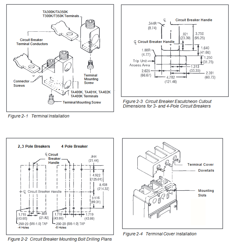
Terminal installation
The wire terminal is fixed with a 7/32 inch socket wrench, with a torque of 6-8 lb. - ft. (8-11 N.m.);
When connecting aluminum wires, a suitable joint compound must be applied to prevent the terminals from overheating and causing accidental tripping or equipment damage.
Circuit breaker fixing
Surface installation should be drilled according to Figure 2-2, while panel installation only requires support holes at the load end. Concealed cover installation should be cut according to the dimensions shown in Figure 2-3;
Tighten the installation screws and washers firmly and not exceeding 28 lb. in. (3 N.m.);
The side of the circuit breaker is labeled with a wiring diagram of the accessories. If it is not visible after installation, it needs to be recorded in advance.
Wiring specifications
The control power supply is 24VDC, the trip unit load is 45mA, and the positive and negative poles must be connected to the corresponding terminals (No. 6+24V/No. 5 NEG). Reversing the connection will damage the electronic protection function;
The regional interlocking function requires the removal of the factory jumper between terminals 2 and 3. If it is not removed, it will be in a self interlocking state;
The four wire system requires the installation of a neutral current sensor at the neutral pole, arranged according to the dimensions shown in Figure 2-6.
Rated plug selection
The release unit needs to be matched with the corresponding rated plug, with specifications as shown in the table below:
The rated current of the trip unit can be selected according to the rated plug specifications
125A 63A、70A、90A、100A、110A、125A
250A 125A、150A、160A、175A、200A、225A、250A
400A 200A、225A、250A、300A、350A、400A
Terminal torque and protection
The torque of the wire/load terminal is determined according to the model, and the core specifications are shown in the table below:
Terminal model material applicable wire torque value (lb. in./N.m.)
TA300K/T300K Aluminum/Copper 3-350 AWG 275/31
TA350K/T350K Aluminum/Copper 250-500 AWG 375/42
TA402K Aluminum 500-750 AWG 550/62
Ladder type terminals (TA400K/TA401K, etc.) must be equipped with matching terminal shields and warning labels must be affixed to the upper part of the circuit breaker cover plate;
When wiring, it is necessary to maintain the original factory electrical clearance and creepage distance to prevent high voltage hazards.
Parameter Settings
Insert the Digitrip OPTIMZER handheld programmer into the programming port, set the INCOM address and trip unit current parameters;
Parameters can also be set through the circuit breaker interface module or IMPACC Series III software.
Manual operation method
The manual operation of the circuit breaker is achieved through the operation handle and PUSH-TO-TRIP button, without additional electric operation requirements. Key rules:
operating handle
There are three positions: ON, OFF, and release. The cover plate is engraved with ON/OFF, and the handle color bar is marked with red=ON, green=OFF (reset), and white=release;
Reset after tripping: simply turn the handle to the extreme OFF position. The reset button is only used to reset the fault indicator light and does not affect the mechanical reset of the circuit breaker.
PUSH-TO-TRIP button
Used to trigger the trip function and regularly test the flexibility of the operating mechanism;
Use a small screwdriver to operate, designed for mechanical triggering.
Safety principle: After the circuit breaker is tripped, it is strictly prohibited to close it again until the fault is identified and eliminated.
Inspection and on-site testing
This series of circuit breakers is designed for maintenance free use and only requires limited regular inspections and testing. All operations must be performed with power off. The core requirements are:
Daily inspection (4-1 to 4-7)
Cleaning: Use a lint free dry cloth/brush/vacuum cleaner to remove dust, do not blow debris into the interior of the circuit breaker, and investigate the source of pollution;
Mechanical testing: repeatedly turn the handle to ON/OFF to ensure that the mechanism is not stuck. If it is stuck, replace the circuit breaker;
Trip test: Press PUSH-TO-TRIP in the ON position and repeatedly trip reset close. If the reset fails, replace the circuit breaker;
Component inspection: Check the cover plate, handle, and base for cracks, paint peeling, and discoloration. If they are severely damaged, replace them;
Terminal inspection: Check that the terminals are not loose or overheated (discoloration/insulation melting/arc erosion). If there are no problems, do not tighten them randomly. If there is overheating, clean/replace the terminals and restore them to their original factory condition;
Installation component inspection: tighten loose installation screws;
Environmental inspection: Check for chemical corrosion, personal/fire hazards in the installation area.
General on-site testing
Execute according to NEMA standards and test the functionality of the Digitrip OPTIM trip unit using the OPTIMIZER handheld programmer.
Grounding fault trip unit test (mandatory requirement)
Regulatory requirements: According to NEC 230-95-C, the grounding fault protection system must undergo performance testing when newly installed, and written test records must be retained in accordance with UL 1053 requirements for inspection by inspection agencies;
Test power supply: Use a 0-24V low-voltage, high current AC source, and do not only test through neutral sensors (the trip unit is powered by phase current, not neutral current);
Trip test: Apply a current of 125% of the ground fault setting value to any phase, and the circuit breaker should trip within 1 second. The alarm indicator light (if any) should be activated, and the three phases should be tested separately;
Non trip verification:
Four wire system (with neutral sensor): current flows in from one phase, neutral sensor flows out, circuit breaker does not trip, and three phases are tested separately;
Three wire system (without neutral sensor): Current flows between any two phases without tripping the circuit breaker, and all phase combinations are tested separately;
Attention: On site testing is only for functional verification and cannot be used for on-site calibration. Temporary wiring for testing must be restored to its original state before power can be transmitted.
Safety Warning and Disclaimer
Core safety requirements: All installation, maintenance, and testing operations must be powered off and verified to have no voltage to avoid high voltage causing death/serious injury/property damage;
Material protection: Do not use corrosive commercial cleaning agents to prevent damage to nameplates and molded parts;
Nuclear application reminder: This instruction applies to general commercial scenarios, and additional instructions for nuclear facility safety related applications need to be obtained from Eaton;
Disclaimer: Eaton shall not be liable for any misuse or installation of the product. This statement is not exhaustive and does not provide any express or implied warranties. Eaton shall not be liable for any special, indirect, or consequential damages.

- YOKOGAWA
- Reliance
- ADVANCED
- SEW
- ProSoft
- WATLOW
- Kongsberg
- FANUC
- VSD
- DCS
- PLC
- man-machine
- Covid-19
- Energy and Gender
- Energy Access
- Renewable Integration
- Energy Subsidies
- Energy and Water
- Net zero emission
- Energy Security
- Critical Minerals
- A-B
- petroleum
- Mine scale
- Sewage treatment
- cement
- architecture
- Industrial information
- New energy
- Automobile market
- electricity
- Construction site
- HIMA
- ABB
- Rockwell
- Schneider Modicon
- Siemens
- xYCOM
- Yaskawa
- Woodward
- BOSCH Rexroth
- MOOG
- General Electric
- American NI
- Rolls-Royce
- CTI
- Honeywell
- EMERSON
- MAN
- GE
- TRICONEX
- Control Wave
- ALSTOM
- AMAT
- STUDER
- KONGSBERG
- MOTOROLA
- DANAHER MOTION
- Bentley
- Galil
- EATON
- MOLEX
- Triconex
- DEIF
- B&W
- ZYGO
- Aerotech
- DANFOSS
- KOLLMORGEN
- Beijer
- Endress+Hauser
- schneider
- Foxboro
- KB
- REXROTH
- YAMAHA
- Johnson
- Westinghouse
- WAGO
- TOSHIBA
- TEKTRONIX
- BENDER
- BMCM
- SMC
- HITACHI
- HIRSCHMANN
- XP POWER
- Baldor
- Meggitt
- SHINKAWA
- Other Brands
- other brands
- UniOP
- KUKA
- IBA
-
Metso XZB10025-011T12 - Moog Valve 9650962700
-
Metso XZB10025-010T12 - Moog Valve 9650965300
-
Metso-SP Transmitter Cable - Operating Unit with 10m Cable
-
Harkila Metso Hybrid - Hunting Jacket Willow Green
-
Metso ND8221/S1 - Neles Valve Positioner
-
Metso METSO10119 - ScreenCheck Component
-
Metso LK-2025 - Linkage Kit
-
Metso A416733 - IQweight External Air Gap Temperature Sensor
-
Metso RKC22MT - Automation Component
-
Metso A413281 - Automation Board
-
Metso LCP9HLY - Stainless Steel Enclosure
-
Metso NP704S/B1S1 - Pneumatic Positioner with I/P Converter
-
Metso BAH3 - Slurry Seal Type
-
Metso A413531-03 - PLC Module Chassis Rack
-
Metso P4610004 - MCAI Communicator Controller
-
Metso QN2AN03HDM - Quartz Valve Positioner Stonel
-
Metso RKW-352-XZ - Automation Component
-
Metso A4300081 - Kajaani LCD Display
-
Metso A428026 7B - Kajaani Rectifier Unit 1
-
Metso 202218 - Kajaani Sensor Power Supply SR 902660
-
Metso 9150 316SS CSTL - Jamesbury 150-2" BN50 Valve
-
Metso 81806 - IOP101 Module
-
Metso STOM000272 - Paper Bushing CR38
-
Metso 1975413 - Chain Hoist Links
-
Metso IMO G053-191597 - Minor Seal Kit
-
Metso VAL0087418 - Cylinder Valmet NTS6LV
-
Metso A413061 - DMU Board VPA 420355-4B
-
Metso P2620-80/25-100 - Automation Component
-
Metso VAL0035292 - Automation Component
-
Metso A413721 - Automation Component
-
Metso ST600 - Automation Component
-
Metso P4500001 - Automation Component
-
Metso SDBX/RA2 - CAT x KVM Extender
-
Metso D201126-DI8 - Digital Input Module
-
Metso D201189L - AI8H Analog Module
-
Metso NA004418 LK1016 - Wafersphere Actuator Mounting Bracket
-
Metso RKN172MTT - Repair Kit
-
Metso MM0311584 - Air Filter Kit RadialSeal
-
Metso 181517 - IOP301 Isolated Analog Input Module
-
Metso RAU3906506 - Automation Component
-
Metso 181208 - IOP332 Digital Input Module
-
Metso A413760 - AIF2C PCB Module
-
Metso 006 1089 36 - Shaft Bearing Seal
-
Metso A413046 - Automation Component
-
Metso VKJ650 - Automation Brake Component
-
Metso LK-1875 - Linkage Kit
-
Metso D201193L - FI4S24 Frequency Input Module
-
Metso D200533 - BIU82 Binary Input Module
-
Metso 500838-M1 - Impeller Pump Release Collar Assembly
-
Metso 2.00SB2ALUS19A - Pneumatic Cylinder 1.375 Stroke
-
Metso D201351 - RES Reserve Module
-
Metso A416100 - IQMoisture Spare Part Kit Halogen Lamp
-
Metso Slurry Pump - Back Liner
-
Metso 7088010042 - Bronze Lantern Ring
-
Metso IMC-101-M-SC - Industrial Media Converter
-
Voith S1-S1-CAM-ENCL - Metso Pump Cmare Housing & Bracket
-
Metso A4430726V1.1 - Kajaani Connection Box CI 4-9-10
-
Metso A413016 - NCU2 PLC Board
-
Metso D202213P - MBMT80 Base
-
Metso A413135 - AOU-4 Analog Output Board
-
Metso NP 724A - Pneumatic Valve Positioner
-
Metso A413246 - Automation Controller Module
-
Konaflex VKJ-650 - Disc Brake Set Pair
-
Metso WIN3096535D - Core Chuck
-
Metso D201380 - MBR Base with IBC & IPS
-
Metso D202213L - MBMT80 Base Module
-
Metso 181571 - IOP337 PLC Module
-
Metso MF0588336 - Main Hydraulic Filter
-
Metso 181504 - IOP303 RTD Input Module
-
Metso A413240 - PIC2 Board
-
Denver 566534PS - Case Liner Gland Side SRL Frame 2
-
Metso 181508 - IOP322 Digital Input Module 120V
-
Metso 181520 - IOP351 Relay Output Module Form A/B
-
Metso 181220 - IOP351 Relay Output Module
-
Metso A413150 - BOU 8 Binary Output Module
-
Metso 128400-M1 - Impeller
-
Metso D201379 - MBB Base with IBC & IPS
-
Metso 205181 - T/B MTD PRWSW Assembly
-
Metso QPX1C/K15 - Jamesbury Quadra-Powr X Actuator Valve
-
Harkila Metso Winter - Hunting Jacket Willow Green
-
Metso NE724A/A-L - Electro-Pneumatic Positioner
-
Metso PACP-100-80-31 916 - Automation Component
-
Metso 81814 - Automation Component
-
Metso ER-12-01-M-CT - Automation Board
-
Metso ELO24 - Automation Board
-
Metso A413000 - Valmet Neles CPU PLC Board
-
Metso XL-2213-0525 - Mainframe Bushing
-
Metso D100097 - ECR Extension Module
-
Metso 804511 - Filter Housing Assembly
-
Metso S420154 - Automation Rack Chassis
-
Metso M851232 - Automation Module
-
Metso D100532 02 - Automation Board
-
Neles QPX1C/M - Ball Valve with Quadra-Powr X Actuator
-
Metso 181535 - IOP322 Isolated Analog Output Module
-
Metso RKN-184-XTZ - Ball Valve Seat Repair Kit 4"
-
Metso N22022621 - Metal Plate
-
Metso 181560 - IOP341 Positioner Module
-
Metso LT 1213 S - Filter Service Kit for CAT C12 Engine
-
Aq-Matic 0032-99000 - Valve Diaphragm
-
Metso D200535 - BOU8 Output Board
-
Metso EDS-305-M-SC - Ethernet Switch
-
Metso 80424 - IOP110 Analog Output Module
-
Metso IOP351 - Relay Output Module Form A/B
-
Metso 181572 - IOP342 Module
-
Metso 1-1-2A3600TT - Ball Valve 1.5"
-
Metso A413154 - BOU8-4 Output Module
-
Metso A413140 - Valmet BIU 8 Board
-
Metso D201139 - IPS Power Supply type DDC7940
-
Metso PGH P411382-2000 - Metal Feed/Filtrate Hose
-
Valmet 503201404 - Automation Board
-
Metso 181507 - IOP331 Controller Module
-
Metso A413141 - BIU82 Binary Input Module
-
Metso KSD7447686 - Pneumatic Cylinder 5" Bore
-
Metso APL3003850 - Automation Component
-
Metso D201135L - Automation Controller
-
Metso A413125 - AIU8 Analog Input Module
-
Metso A413325 - IPU Power Unit
-
Metso 181573 - IOP346 PLC Module
-
Metso A413143 - BIU84 Binary Output Module Card
-
Metso A413152 - BOU82 Output Module
-
Metso PDP603 - Distributed Processing Unit 181555
-
Metso PDP601 - Distributed Processing Unit 181555
-
Metso A413040 - DCS Board DCU
-
Metso A413082 - CPU Processor Module
-
Valmet TI4W3 - Temperature Input Module
-
Valmet FI4S24 - Frequency Input Module
-
Metso 1064669615 - Fulcrum Bar
-
Valmet 181206 - IOP330 Digital Input Module

KONG JIANG

Add: Jimei North Road, Jimei District, Xiamen, Fujian, China
Tell:+86-15305925923