
K-WANG


EATON CG Controller
EATON CG Controller Controller
Basic specifications and compliance requirements
Application and positioning: CG Controller is a dedicated monitoring/controller for emergency lighting systems, which can control up to 32 sets of CG 2000 or ZB-S systems of the same type per unit. It belongs to building/enterprise safety equipment and is only allowed to be operated by professionals. Unauthorized operation may cause lighting system failure and safety accidents.
Compliance standards: The product complies with VDE 0108/10.89, DIN/VDE 0805/11.93, IEC 950 standards, developed/produced/tested according to DIN EN ISO 9001, meets the EU EMC Directive (89/336/EEC) and Low Voltage Directive (73/23/EEC), and has CE certification.
Core security requirements
The equipment must operate in a undamaged and fault free state;
All operations require disconnecting the system power supply and distinguishing between normal/emergency mode power supply;
Before operation, the emergency lighting system must be tested according to the installation instructions;
Comply with the safety regulations and accident prevention requirements of the host country, and report and rectify any malfunctions immediately.
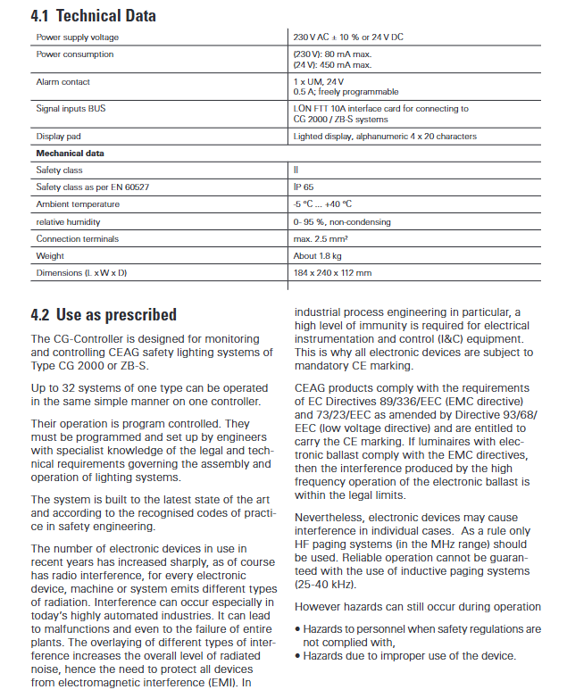
Core technical parameters
The key technical parameters of the controller are hard operating indicators that cannot be deviated from without special instructions, as shown in the following table:
Specific project parameters
Supply voltage 230 V AC ± 10% or 24 V DC
Maximum power consumption 230V: 80mA; 24V:450mA
Alarm contact 1 × UM, 24V 0.5A, freely programmable
Communication interface LON FTT 10A interface card, CG-S BUS bus
Display module 4 × 20 characters with backlit alphanumeric LCD
Security/Protection Level Security Level II, IP 65
Working environment temperature: -5 ℃~+40 ℃; Humidity: 0-95% (no condensation)
The maximum compatibility of the wiring terminal is 2.5mm ² wire
Physical specification weight: approximately 1.8kg; size: 184 × 240 × 112mm (length × width × depth)
Installation and initial setup
The installation process is simple and supports two fixed methods. After completing the wiring, basic parameter configuration is required. The core steps are:
Assembly method: ① Drill holes and fix according to the drawing, and tighten the screws with just fingers; ② Can be directly installed on a 35mm DIN rail.
electrical connection
Power wiring: Complete 230V AC/N/PE or 24V DC wiring according to the diagram, equipped with freely programmable floating contacts;
Bus wiring: The BUS bus of the emergency lighting system must be connected to the A (2) B (2) terminals of the controller, with each input containing 4 terminals.
Initial necessary settings
After turning on the power, first set the current time and date, and confirm with the Menu/ENTER key;
Enter Menu → Setup Device → Find device autoim to complete the automatic registration of emergency lighting equipment;
Calibrate all system clocks to ensure accurate logging time.
Operation core: buttons, display and status/fault priority
The controller completes all operations and status visualization through physical buttons, LCD display screen, and LED indicator lights. The operation logic is clear, and status/faults are displayed according to priority:
Key definition: The core keys are Menu, ENTER, up and down (/), left and right (/) keys, each with multiple functions. For example, the Menu key can return to the main screen/previous menu, the ENTER key can confirm/open submenus, and the up and down keys can select menus/adjust values.
Dual display system
LCD display screen: 4 lines display, including software version, status, fault, time and date; Automatically return to the main screen after 3 minutes of no button operation, and the backlight will light up for 3 minutes after the button is triggered;
LED indicator light (front panel): green=normal operation, yellow=test mode, red=fault status. A single light on indicates that the corresponding status is in effect.
Priority of status display (from high to low): DT operation>FT operation>lockout>battery operation>UV-A mains fault>deep discharge protection>manual reset>DLS/TLS fault. High priority status will override low priority status and restore the original status after disappearing.
Fault display priority (from high to low): Device communication fault>Device mains fault>UV S3/S4 mains fault>UV RS485 mains fault>Total fault>Transmission fault>Battery fault>Converter fault>Charging/isolation fault>Lamp fault>Minimum duration fault.
Total fault: defined as the simultaneous occurrence of ≥ 2 types of faults, including 8 types of faults such as battery interruption, charging module failure, communication failure, and lighting failure. Individual faults do not trigger total faults.
Core menu functions
All operations of the controller are completed through the main menu → sub menu hierarchy. The main menu includes Test、Block/reset、Info device、Setup CG-Controller、Setup device、Memory Card The six core modules have the following functions:
Test "menu: The core is emergency lighting system testing, supporting functional testing (FT) and duration testing (DT). It can start FT/DT for single/all devices, or cancel the running DT test. The test is confirmed to start by pressing the ENTER key.
<Block/reset>menu: ① Block all/Release all: One click lock/release all devices, select and execute immediately; ② Manual reset: After a mains power failure, manually reset the device one by one, and automatically exit the menu when there are no devices to be reset.
Menu "Info device": System status monitoring core, supporting viewing of device status, fault information, circuit status, lighting status, DLS/TLS/3PhW status, charging/battery status of CG 2000/ZB-S devices. Items with faults will be marked with *, and up to 4 types of status/faults can be displayed.
<Setup CG Controller>menu: Controller local configuration, core functions include language selection (German/English), time and date settings (supports daylight saving time/standard time switching), FT/DT test cycle settings (FT defaults to 7 days, DT defaults to 12 months), relay programmable settings (default linkage deep discharge protection/total fault), password management (6-digit password, can be activated/disabled), network mode (default main mode, supports observer mode).
Test cycle safety function: The set FT/DT time will be synchronized to all devices, and the devices will automatically save the test time plus 1 hour. If the controller fails, the device will automatically execute the test according to this backup time.
<Setup device>menu: Device management, ① Find devices autoim: Automatically find devices (will delete existing device records); ② Adding/deleting manually: To manually add or delete CG 2000/ZB-S devices, a unique device address and NID must be entered; ③ Synchronising clocks: Manually/automatically synchronize all device clocks, triggering automatic synchronization in 8 scenarios (such as automatically checking devices, changing controller time, starting tests, etc.).
Memory Card "menu: SD card management core, supports log viewing/deletion, controller configuration saving/loading, SD card reading/writing of device configuration/text, full device data backup to SD card. When there is no SD card, the logs are stored in the controller EPROM, and the logs stored on the SD card can view detailed fault information.
SD card management and PC software linkage
The SD card serves as the core storage and configuration transmission medium for the controller, and supports batch configuration in conjunction with PC software. The core content includes:
SD card storage files: Fixed naming format, core files include configcg.dat (controller configuration), logbook.dat (running logs), as well as device configuration files (CG 2000: configxx.dat; ZB-S: zbscfgxx. dat), device text files (CG 2000: textexx.dat; ZB-S: zbstxtxx. dat), where xx is the device address (01-32).
SD card core operation: ① Save/load controller configuration; ② Read/write configuration/text of a single device; ③ Batch backup of all device data (configuration+text) to SD card; ④ View/delete logs, logs cannot be recovered after deletion.
PC software linkage: The PC side generates controller/device configuration files, stores them on the SD card, and inserts them into the controller. The controller automatically reads the new configuration and completes device search. It can batch transfer the configuration/text to the marked devices to be updated, and supports cancellation/termination of the transfer process.
Fault handling and logging
Fault handling: Faults are displayed by priority on the LCD, and the total number of faults can be entered into the "Info device" menu to view the specific fault type; Relays can be linked to fault alarms, and the triggering time increases with the number of controlled devices (due to the need to complete a round of status polling).
Log recording: The system automatically records all running, testing, and fault events, which are stored on the SD card by default or in EPROM when there is no SD card; The log can be viewed for detailed information (including time, device, and fault type) through LCD, or exported to PC through SD card. Deleting the log is an irreversible operation.

- YOKOGAWA
- Reliance
- ADVANCED
- SEW
- ProSoft
- WATLOW
- Kongsberg
- FANUC
- VSD
- DCS
- PLC
- man-machine
- Covid-19
- Energy and Gender
- Energy Access
- Renewable Integration
- Energy Subsidies
- Energy and Water
- Net zero emission
- Energy Security
- Critical Minerals
- A-B
- petroleum
- Mine scale
- Sewage treatment
- cement
- architecture
- Industrial information
- New energy
- Automobile market
- electricity
- Construction site
- HIMA
- ABB
- Rockwell
- Schneider Modicon
- Siemens
- xYCOM
- Yaskawa
- Woodward
- BOSCH Rexroth
- MOOG
- General Electric
- American NI
- Rolls-Royce
- CTI
- Honeywell
- EMERSON
- MAN
- GE
- TRICONEX
- Control Wave
- ALSTOM
- AMAT
- STUDER
- KONGSBERG
- MOTOROLA
- DANAHER MOTION
- Bentley
- Galil
- EATON
- MOLEX
- Triconex
- DEIF
- B&W
- ZYGO
- Aerotech
- DANFOSS
- KOLLMORGEN
- Beijer
- Endress+Hauser
- schneider
- Foxboro
- KB
- REXROTH
- YAMAHA
- Johnson
- Westinghouse
- WAGO
- TOSHIBA
- TEKTRONIX
- BENDER
- BMCM
- SMC
- HITACHI
- HIRSCHMANN
- XP POWER
- Baldor
- Meggitt
- SHINKAWA
- Other Brands
- UniOP
- KUKA
- IBA
- Beckhoff
-
LTI SC52.0040.0012.0000.0 - Servo Drive
-
Lti SC52.0040.0012.0000.0 - Servo Drive
-
Milton Industries LTI Tool By Milton LT1240 - 1/2" Drive Lugnut Remover
-
LTi Drives SO84.200.P030.0000.0-W - Servo Spindle Drive
-
LTI DRIVES LSP08-035-320-30-B0R1PY170 - Servo Motor
-
LTI DRIVES SE84.200.SC00.0001.0-W - Servo Drive
-
Lust CDE34.005.W2.2 - Lti Drives Controller
-
LTi SO84.012.0030.0011.2 - ServoOne Servo Drive
-
LTi Drives SO CM-P.0010.11.00.0 - Servo Drive Controller
-
LTi CDE34.017.W3.0 - Servo Drive
-
LTI Drives CDB32.004, C2.0,SH - Positioning Controller
-
LUST CM-CAN1 - LTi DRIVES Communication Module
-
LTi SO84.012.1030.0000.2 - Servo Drive
-
LTI MOOG CDE54.044 - PITCHMASTER FREQUENCY CONVERTER 181-01019
-
MOOG LTI 181-01019 CDE54.044 - PITCHMASTER FREQUENCY CONVERTER
-
Lust LTi Drives CDE34.010,D2.0 - Servo Drive Controller
-
LTI SO84.032.0003.0101.2 - Servo Drive
-
Seagate 9CC132-302 Harris LTI-CS IRT-34-0021-01 - Hard Drive 160GB
-
LTI SO84.032.0003.0001.2 - Servo Drive
-
LTI SO24.007.0070.0000.1 - SERVO CONTROLLER
-
LTi drive CDA32.003.C3.0.H05-01.PC1 - Servo Drive
-
LTI SO84.016.0030.0000.2 - SERVO CONTROLLER
-
LUST LTI CD A34.008,W1.4, BR - SERVO DRIVE
-
MOOG LTI 181-01019 CDE54.044 - PITCHMASTER FREQUENCY CONVERTER
-
LTI MOOG 181-01019 - PITCH Master Servo Drive CDE54.044
-
LTI SERVO ONE SO84.045.0030.0001.2-W - Drive
-
LUST LTi SO84.032.0040.0000.2 - SERVO ONE DRIVE
-
LTi Drives LSH-074-2-30-3 20/T1,G6.1M - SERVO MOTOR
-
LTI SO84.016.0000.0101.2 - servo drive
-
LTI SA54.0550.0033.0000.0 - Servo Drive
-
LTI SA54.0550.0033.0000.0 - Servo Drive
-
LTI LT 4850 - 3/8" Drive 3-Pc Twist Socket Transmission Drain Plug Removal System
-
LTI Tools LT4400-30 Lock Technology - 3/4" Twist Socket 1/2" Drive Lugnut Remover
-
LTI Tools LT-1400C - 1/2 Drive Wheel Torque Extension Tool
-
LTI Tools LT1250 - 1/2" Drive Dual Sided Socket Lug Nut Remover Tool
-
LTI SO84.032.0003.0101.2 - Servo Drive
-
LTI MOOG 181-01019 - PITCH Master Servo Drive CDE54.044
-
MOOG LTI 181-01019 CDE54.044 - PITCHMASTER FREQUENCY CONVERTER
-
MOOG LTI 181-01019 CDE54.044 - PITCHMASTER FREQUENCY CONVERTER
-
MOOG LTI 181-01019 CDE54.044 - PITCHMASTER FREQUENCY CONVERTER
-
LTI SA54.0550.0033.0000.0 - Servo Drive
-
LTI Tools LT-4800 - 7 Piece Twist Socket 3/8" Drive Oil Drain Plug Removal Set
-
LTI SA54.0550.0033.0000.0 - Servo Drive
-
LTI Drive SO24.007.00300000.0 - Servo Drive
-
LTI TOOLS LTI 1400-I - Drive Wheel Torque Extension
-
LTI Tools LT4400-3 - 3/4" 19mm Twist Socket 1/2" Drive Lugnut
-
LTI TOOLS LTI 1400-BB - Drive Wheel Torque Extension
-
LTI SO84.032.0003.0101.2 - Servo Drive
-
LTI Tools LT-4512 - 3/8" Drive 12mm Twist Socket
-
LTI MOTION Luster SO84.032.0003.0001.2 - Servo Drive
-
LTI Tool By Milton LT1600P - 1" Drive Torx Stick
-
LTI Lust VF1424L,HF,OP2,S56 - Variable Frequency Drive
-
LUST CDA32.004,C1.4,H08,B0 - SERVO DFRIVE CM-CAN1 Module
-
LTI SO84.045.0002.0001.2-W - Drive
-
LTI Lust VF1404M,C9,PT1,BR1 - Inverter Type VF1404M
-
LTI SA54.0550.0033.0000.0 - Servo Drive
-
LTI Tools LT-1400C - 1/2" Drive Wheel Torque Extension
-
Lust LTI DRiVES CDA32.006, C3.0, H09 - Variateur De Fr茅quence Frequency Inverter
-
LTI MOOG CDE54.044 - PITCH master SERVO DRIVE
-
LTI MOOG CDE54.044 - PITCH master SERVO DRIVE
-
LTI SO84.143.0020.0101.2-W - servo drive
-
LTI MOTION SC34.0200.0011.0000.0 - Servo drives
-
LTI SO84.032.0003.0001.2 - Servo Drive
-
LTI DRIVES GmbH MS100 - Assembly Set Mounting Kit
-
LTI SO84.032.0003.0001.2 - Servo Drive
-
LTI SO84.032.0003.0001.2 - Servo Drive
-
LTI MOTION SO84.032.0003.0101.2 - servo drive
-
LTI SO84.032.0003.0101.2 - Servo Drive
-
LTI MOOG CDE54.044 - PITCH master SERVO DRIVE
-
LTI MOTION CDE32.004.C2.4 - Servo drives
-
LTI CDD34.032锛學x.x锛孊R锛孭C1 - Servo Drive
-
Lust LTI DRiVES CDA32.006, C3.0, H09 - Inversor De Frecuencia Frequency Inverter
-
Lust SO84.008.0030.1000.0 - Servo One LTi Drive
-
LTI MOTION SO84.032.0003.0101.2 - Servo drives
-
LUST LTi CDA32.004,C1.4 - SERVO DRIVE
-
LTI MOOG CDE54.044 - PITCH Master SERVO DRIVE
-
LTI KEBA CDB32.004 C2.7, SH - PN: 08673530 Frequency Inverter
-
LTI Tools LT-1400C - 1/2" Drive Wheel Torque Extension
-
LTI LT1400-E - 1/2" Drive Wheel Torque Extension
-
LTI MOOG 181-01019 - PITCH master SERVO DRIVE CDE54.044
-
LTI LSN-097-0510-30-560/T1 - Actuator Motor
-
LTI Tools LT 4800 - 7 Piece 3/8" Drive Twist Socket Oil Drain Plug Removal System
-
LTI DRIVES GmbH MS100 - MONTAGESET Assembly Set Mounting Kit
-
Lti SC52.0040.0012.0000.0 - Servo Drive
-
LTI DRIVES GmbH MS100 - Juego De Montaje Assembly Set Mounting Kit
-
LTi DSM4-14.2-21R83-200 - Drives servomoteur Servo Motor
-
MOOG CDE 54.044.GDA - Pitch Master Industrielle Turbine Lti Drive
-
LTI SO24.004.0030.1000.0 - Servo Drive Controller
-
Lti MOOG CDE54.044 - Pitch Master Servo Drive
-
Lust LTI DRiVES CDA32.006, C3.0, H09 - Inverter
-
LTI MOTION GMBH CDB34.006,W3.0,PC1,H39 - Frequency inverter
-
LTI SO84.032.0003.0001.2 - Servo Drive
-
MOOG CDE 54.044.D - Pitch Master Industrielle Turbine Lti Drive
-
LTI TOOLS LT-1460 - 1/2" DRIVE WHEEL TORQUE EXTENSION KIT 5 PIECE SET
-
Lust Cdb32.003, C2.4 - Lti Drives Servoregulador Frecuencia Servo Controller Inverter
-
Lust LTI DRIVES CDA32.006, C3.0, H09 - Frequency Inverter
-
Lust Lti SO82.004.0030.0000.2 - Servo Drive
-
LTI MOTION SC34.0200.0011.0000.0-SL - Servo drives
-
LTI MOTION SA54.0075.0033.0000.0 - Servo drives
-
LTI MOTION SC32.0075.1011.0000.0 - Servo drives
-
LTI Servo-One Junior SO22.006.0080.1000.0 - Servo Controller Servoregler
-
LUST CDA32.004, C1.4, H08, B0 - Servo Drive & LTI CM-CAN1 Module
-
LTI DRIVES LSP08-035-320-30-B0R1PY170 - Servo Motor
-
LUST LTI CDA32.004,C1.4.H08.B0 - SERVO CONTROLLER DRIVES
-
LUST LTi DRiVES CDS44.072LC1.2 - Servo Drive
-
Lti Servo-One Junior SO22.006.0082.1000.0 - Servo Controller Servoregler
-
LUST CDA32.008,C2.0,HF - Lti DRIVES Spindle Drive Inverter
-
LTI SO22.003.0082.0000.0 - Servo Drives One junior Servo Controller Servoregler
-
Lust Lti Drives CM-CAN1 - Communication Module
-
LUST Lti Drives Vf1202s, G8, I6 - Frequency Inverter Drive
-
LTI DRIVES BR-090.03.540.UR.H38 - Bremswiderstand Brake Resistor
-
LTi DRIVES PM-E40.2DRA054P - Wind Turbine Pitch Control Inverter
-
LTi Drives GmbH br-110.01.540-UR - Brake Resistor
-
LTI Drives LSN-097-0960-30-0560/T1,S4,B - Servo Motor
-
LUST CDA34.006.C2.0 - LTI Drives Servoregler
-
LUST LTI DRIVES SERVO ONE JUNIOR SO24.002.0020.0000.1 - Servo Drive Controller
-
LTI MOTION SO84.032.0003.0001.2 - Servo drives
-
LTI DDTD750V2-120 - IBOP ACTUATOR CYLINDER FOR TOP DRIVE
-
LTI CDE32.004, C2.4 - SERVO DRIVE
-
LUST LTI DRIVES CDD34.017 W3.4PC1 - Servo Drive Controller
-
LTI CDA3208,C3,0,HF - AC SERVO DRIVE
-
LUST LTI DRIVES LSH-074-3-30-560/T1,G6.1S - SERVO MOTOR
-
LUST Lti CDB32.004.C2.4.SH - AC Servo Drive
-
LTi CDA32.006, C3.0, H09 - Servo Drive
-
LTI SO22.003.0010.0000.0 - Servo Drive Servo one junior Servoregler Controller
-
LTi Drives DSM4-14.2-21R83-200 - Servo Motor
-
LUST Lti Drives Lsh-097-1-30-560/T1, 1R - Servomotor
-
LTI 1237 - 7 Piece 1/2" Drive Flip Socket Set

K-JIANG

Add: Jimei North Road, Jimei District, Xiamen, Fujian, China
Tell:+86-15305925923