
K-WANG


EATON MICRO PANEL XP-702 Operating Manual
EATON MICRO PANEL XP-702 Operating Manual
Equipment Core Description
1. Product positioning and core functions
XP-702 is an industrial PC with an open system architecture, mainly used in the field of mechanical/system manufacturing, suitable for tasks related to industrial automation. There is no description of the operating system and application software, only indicating hardware usage specifications.
2. Core version and specifications
The device is available in two major processor versions: 1GHz (XP-702-C/E series) and 1.8GHz (XP-702-D/F series), with the E/F series only available in North America; The hardware forms are divided into BOX models without display screens and 8.4/10.4/12.1/15-inch models with infrared touch screens. The core configurations of each specification are as follows:
Processor version core configuration applicable to device types
1GHz (C/E) X86 Celeron M processor, 1024M DRAM, no active cooling unit BOX model+full-size with screen model
1.8GHz (D/F) X86 Pentium M processor, 2048M DRAM, standard active cooling unit BOX version+full-size screen version
3. Packaging Content
The basic accessories are the host and one power connector, and additional accessories vary depending on the specifications:
1.8GHz (D/F) full series: including 1 active cooling unit;
E/F series full range: including 4GByte system CF card and 1GByte data CF card;
Equipped with a screen: including a corresponding number of installation brackets and sealing strips, the number of brackets increases with size.
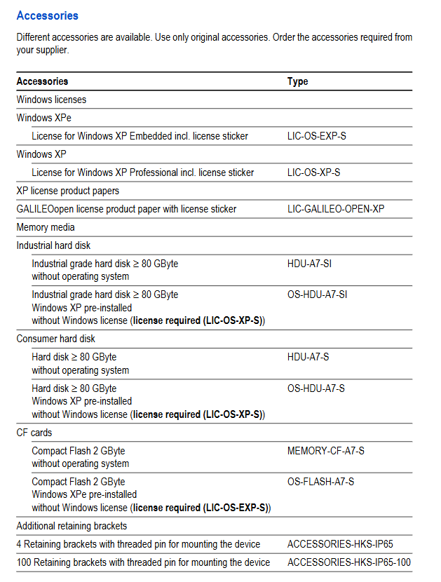
4. Original accessories
Only Eaton original accessories can be used, mainly including:
System authorization: Windows XPe/XP Professional authorization sticker;
Storage medium: ≥ 80GB industrial/consumer grade hard drive, 2G CF card (pre installed system);
Installation accessories: IP65 rated installation bracket (single package/100 pieces);
Equipment accessories: infrared touch frame replacement parts, active cooling unit (ACCESSORIES-FAN-700-S).
5. Equipment identification
There is a nameplate on the back of the equipment, which includes the manufacturer's address, model, power supply requirements, part number, serial number, production date (week/year), certification mark. After sales support requires providing the part number and serial number.
Safety regulations
Warning symbol grading: The document adopts a three-level warning, DANGER for fatal danger, Warning for serious danger, CAUTION for minor injury/equipment damage, and there are also general information prompt symbols.
Personnel requirements: Only qualified and trained personnel are allowed to install/operate/maintain the equipment. All operators must read and understand the instructions thoroughly, and the use of single page content for operation is prohibited.
General safety taboos
Prohibit the use of equipment for personnel/equipment protection safety functions;
The equipment is prohibited from opening the cover, as there are live parts inside that can easily cause electric shock;
Avoid electrostatic discharge: Before contacting the equipment, touch the grounded metal and do not touch static sensitive components;
Avoid equipment condensation: After sudden changes in temperature and humidity, it is necessary to let it stand at room temperature before turning it on to prevent short circuits;
Avoid UV exposure: To prevent plastic from becoming brittle, keep away from sunlight/UV lamps;
Cleaning taboos: Do not use sharp tools/corrosive cleaning agents to prevent liquids from entering the equipment.
Requirements for use in explosive environments
Can only be used in non explosive areas or ATEX 94/9/EC Zone 22 areas;
When using Zone 22, the grounding resistance of the metal parts that can be touched should be less than 10 ^ 9 Ω to avoid beam discharge and prevent equipment from being impacted. The device must be turned off before inserting or unplugging the connector.
Storage/operation taboos
When reading and writing CF cards/hard drives (CF ACT/HD ACT lights on), power off/unplugging is prohibited. The system must be shut down before power off. It is recommended to use UPS to prevent data loss;
All interface GND terminals must be connected to prevent potential difference from damaging the equipment;
Equipotential current protection: Install equipotential conductors in parallel if necessary, with a cross-sectional area several times that of the cable shielding layer.
Operation and indicator components
Front components: only infrared touch sensor and TFT-LCD display screen; The touch sensor is triggered by blocking the infrared matrix, with a minimum trigger diameter of 7mm and no need to touch the protective panel.
Service side operating components: 2 CF card slots (slot 0 for system card and slot 1 for data card)+card slot eject button+card slot protective cover, used for CF card installation and removal.
Service side indicator LED: 4 in total, with the following functions:
|LED Name | Color | Function|
|SUPERY ERR | Red | Illuminates briefly upon power on, remains on after fault/power off|
|Supply OK | Green | Always on during device startup/operation|
|CF ACT | Red | Lights up when accessing CF card|
|HD ACT | Red | Lights up when accessing the hard drive|
Installation specifications
1. Installation foundation requirements
Installation position: The screen version can be installed in the control cabinet/operation panel/console, while the BOX version can only be installed in the control cabinet;
Installation posture: only horizontally installed, vertical installation with a tilt angle of ≤± 15 °;
Environmental requirements: Avoid direct sunlight, with a distance of ≥ 5cm around ventilation openings and ≥ 15cm around heat sources;
Installation surface requirements: The material thickness at the opening should be 2-5mm, the flatness should be ≤ 0.5mm, and the surface roughness Rz should be ≤ 120.
2. Opening size with screen (± 1mm)
Equipment size, hole size (length x width, mm)
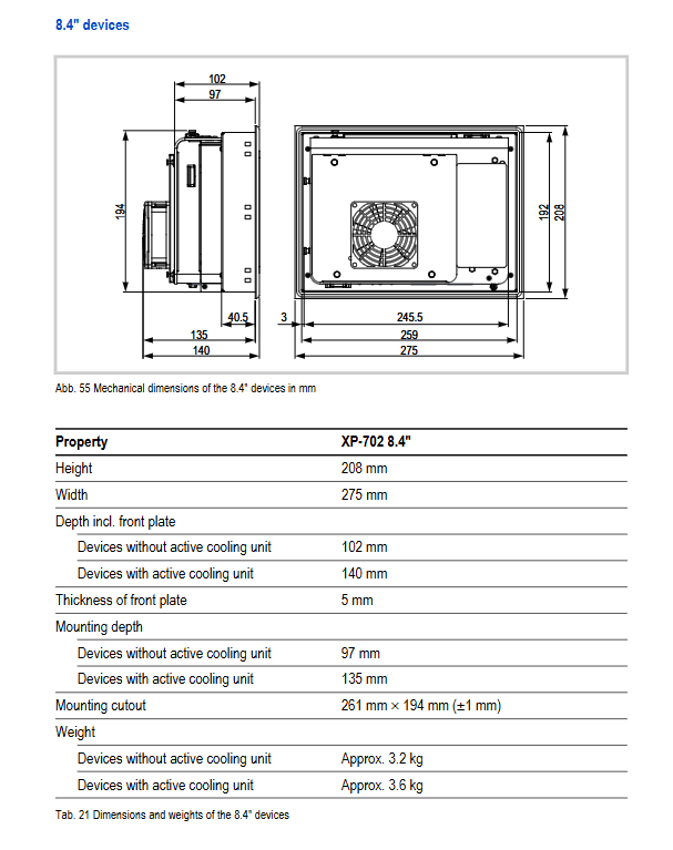
8.4 inches 261 × 194
10.4 inches 329 × 238
12.1 inches 344 × 262
15 inches, 410 x 315
3. Interface wiring requirements
All cables must use shielded wires, and the shielding layer of D-Sub connectors must be connected to the connector housing through metal clamps to achieve low impedance connection, ensuring EMC compliance;
Wiring can only be done by professionals, and incorrect wiring can result in equipment parameters not meeting standards and EMC failure.
4. Core interface parameters
Requirements for the use of key parameters in interface names
Power supply interface 24VDC SELV, Phoenix MSTB 2.5/3-ST-5.08 connector, wiring cross-sectional area 0.75~2.5mm ², torque 0.6~0.8Nm, internal fuse+reverse protection, functional ground connected to shell/0V, no electrical isolation
RS232 (2) 9-pin D-Sub male head, no electrical isolation, GND connected to the enclosure cable length negatively correlated with baud rate, maximum 9600Bit/s at 30m
Ethernet (2) 1 × 1000/100/10Base-T, 1 × 100/10Base-T, RJ45 interface with STP cable, cross line between devices, direct connection to switch, maximum length of 100m, anti vibration/pulling
USB Host (4) USB2.0, no electrical isolation shielding wire, maximum length 5m
PCI 2.1 32-bit, supports only 3.3V card maximum power consumption of 6.6W (2A)
VGA 15 pin high-density D-Sub female shielded cable, standard length 5m
DVI DVI-D single link, only BOX models are equipped with shielded cables, with a regular length of 5m
5. Equipment assembly and fixation
PCI cards/CF cards/hard drives/active cooling units all have standardized installation procedures, and CF cards/hard drives can only be disassembled and installed in a power-off state;
Fixed with screen: When using IP65/NEMA 4X or Zone 22, 8 brackets are required for 8.4/10.4/12.1 inches, and 12 brackets are required for 15 inches; Bracket screw torque ≤ 0.2Nm to prevent equipment damage;
Sealing requirements: During installation, a sealing strip should be installed in the groove of the equipment backplate, and the joint of the sealing strip should be at the bottom of the equipment without gaps/twists.
Equipment operation
Startup: The device has no power switch and starts automatically when powered on. It is necessary to ensure that the card slot 0/hard disk slot is pre installed with the system; When unable to start or encountering errors, refer to the troubleshooting section.
Shutdown: The operating system must be shut down before disconnecting the power supply; Power off for at least 20 seconds during restart to avoid frequent on/off (reduce the lifespan loss of backlight CCFL).
Dual display activation: If the secondary screen is not connected when turning on, the device defaults to single display; To activate, connect a USB mouse, right-click on the desktop ->Graphics Properties ->Multiple Display, select Intel (R) Dual Display Clone, and confirm the settings.
Maintenance and Service
routine maintenance
Infrared touch box: It needs to be cleaned regularly. When it is contaminated, a warning icon will appear on the taskbar. Use a clean, soft, and damp cloth for cleaning. For stubborn stains, spray a small amount of cleaning agent on the cloth; No calibration required;
Lithium battery replacement: The device is equipped with a CR2477 3V 950mAh lithium battery, which provides power for the real-time clock and has a backup time of about 10 years; After replacement, the date and time need to be reset.
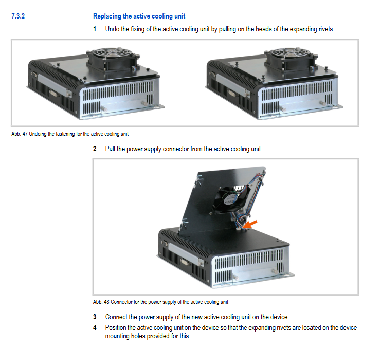
Accessory replacement: The active cooling unit can be replaced by itself, and other accessories/internal repairs can only be completed by Eaton's original factory or authorized repair center. Unauthorized opening of the equipment is prohibited.
Troubleshooting: The document provides clear causes and solutions for common faults such as inability to start, black screen display, touch failure, dual display no signal, date error, and SUPLY ERR light on. Core faults such as backlight damage and BIOS malfunction require factory repair.
Storage, transportation, and disposal
Storage and transportation
Environmental parameters: temperature * * -20~60 ℃ * *, humidity 10~95%, no condensation, in compliance with equipment environmental parameter requirements;
Protection requirements: collision and vibration prevention, use original packaging, and inspect the equipment for damage after transportation.
scrap disposal
The equipment contains lithium batteries (CR2477) and mercury containing cold cathode tubes (<5mg/tube), which may cause explosion/poisoning if handled without authorization. It should be disposed of in accordance with relevant national regulations or returned to Eaton's original factory/sales office;
Equipment material: The shell is made of galvanized steel plate/anodized aluminum, the touch frame is made of polycarbonate, and the protective panel is made of safety glass; The package is paperboard+fluorine free closed cell polyethylene foam, and the shell material is halogen-free.
Core technical parameters
1. System and Storage
Project Parameters
Processor 1GHz (C/E): Celeron M; 1.8GHz (D/F): Pentium M
Memory 1GHz: 1024M DRAM; 1.8GHz:2048M DRAM
Storage slot 2 x CF card Type I/II, 1 x 2.5-inch hard drive slot
Real time clock battery CR2477, 3V, 950mAh, backup time of 10 years
2. Display and Touch Control
Device size resolution, touch sensor, backlight brightness/contrast
8.4/10.4-inch SVGA (800 × 600) infrared touch, 63 × 47/79 × 59 logic channels 2 × CCFL, lifespan 50000h 400cd/m ², 400:1
12.1/15-inch XGA (1024 × 768) infrared touch, 95 × 71/107 × 83 logic channels 2 × CCFL/4 × CCFL, lifespan 50000h 400cd/m ², 400:1
3. Power consumption (24VDC SELV)
Maximum total power consumption and maximum continuous current of processor version
1GHz (C/E) 64.5W (15 inch model) 2.7A (15 inch model)
1.8GHz (D/F) 76.5W (15 inch model) 3.2A (15 inch model)
Universal startup surge current 2A/2s, reverse protection+built-in fuse voltage range 20.4~28.8VDC (rated ± 15%/+20%)
4. Protection and Certification
Protection level: IP65/Enclosure Type 4X on the front side with screen (indoor only), IP20/Enclosure Type 1 on the back side of BOX/device;
Core certifications: EMC (2004/108/EC), ATEX 94/9/EC (Zone 22, 3D), UL 508 (North America);
Compliance standards: IEC/EN 61000-6-2/4 (EMC), IEC/EN 60950 (safety), EN 50178 (electrical equipment).
5. Working environment
Temperature: 0~50 ℃ (no hard drive/industrial hard drive), 0~45 ℃ (consumer grade hard drive, not recommended for continuous use);
Humidity: 10~95%, no condensation;
Anti vibration: IEC/EN 60068-2-6, displacement of 3.5mm at 5-9Hz, displacement of 0.15mm at 9-60Hz, acceleration of 2g at 60-150Hz;
Impact resistance: IEC/EN 60068-2-27, 15g/11ms;
Drop: Complies with IEC/EN 60068-2-31 standard.
Weight and Size (Core)
The BOX model has a height of 194mm and a width of 264mm. It has a depth of 58mm without a cooling unit (weighing 1.9kg) and a depth of 96mm with a cooling unit (weighing 2.3kg); The depth of the screen equipped model increases by 38mm with the cooling unit, and the weight increases by 0.4kg. For example, an 8.4-inch model without a cooling unit weighs 3.2kg, while a 15 inch model with a cooling unit weighs 6.7kg.
- YOKOGAWA
- Reliance
- ADVANCED
- SEW
- ProSoft
- WATLOW
- Kongsberg
- FANUC
- VSD
- DCS
- PLC
- man-machine
- Covid-19
- Energy and Gender
- Energy Access
- Renewable Integration
- Energy Subsidies
- Energy and Water
- Net zero emission
- Energy Security
- Critical Minerals
- A-B
- petroleum
- Mine scale
- Sewage treatment
- cement
- architecture
- Industrial information
- New energy
- Automobile market
- electricity
- Construction site
- HIMA
- ABB
- Rockwell
- Schneider Modicon
- Siemens
- xYCOM
- Yaskawa
- Woodward
- BOSCH Rexroth
- MOOG
- General Electric
- American NI
- Rolls-Royce
- CTI
- Honeywell
- EMERSON
- MAN
- GE
- TRICONEX
- Control Wave
- ALSTOM
- AMAT
- STUDER
- KONGSBERG
- MOTOROLA
- DANAHER MOTION
- Bentley
- Galil
- EATON
- MOLEX
- Triconex
- DEIF
- B&W
- ZYGO
- Aerotech
- DANFOSS
- KOLLMORGEN
- Beijer
- Endress+Hauser
- schneider
- Foxboro
- KB
- REXROTH
- YAMAHA
- Johnson
- Westinghouse
- WAGO
- TOSHIBA
- TEKTRONIX
- BENDER
- BMCM
- SMC
- HITACHI
- HIRSCHMANN
- XP POWER
- Baldor
- Meggitt
- SHINKAWA
- Other Brands
- UniOP
- KUKA
- IBA
- Beckhoff
-
LTI SC52.0040.0012.0000.0 - Servo Drive
-
Lti SC52.0040.0012.0000.0 - Servo Drive
-
Milton Industries LTI Tool By Milton LT1240 - 1/2" Drive Lugnut Remover
-
LTi Drives SO84.200.P030.0000.0-W - Servo Spindle Drive
-
LTI DRIVES LSP08-035-320-30-B0R1PY170 - Servo Motor
-
LTI DRIVES SE84.200.SC00.0001.0-W - Servo Drive
-
Lust CDE34.005.W2.2 - Lti Drives Controller
-
LTi SO84.012.0030.0011.2 - ServoOne Servo Drive
-
LTi Drives SO CM-P.0010.11.00.0 - Servo Drive Controller
-
LTi CDE34.017.W3.0 - Servo Drive
-
LTI Drives CDB32.004, C2.0,SH - Positioning Controller
-
LUST CM-CAN1 - LTi DRIVES Communication Module
-
LTi SO84.012.1030.0000.2 - Servo Drive
-
LTI MOOG CDE54.044 - PITCHMASTER FREQUENCY CONVERTER 181-01019
-
MOOG LTI 181-01019 CDE54.044 - PITCHMASTER FREQUENCY CONVERTER
-
Lust LTi Drives CDE34.010,D2.0 - Servo Drive Controller
-
LTI SO84.032.0003.0101.2 - Servo Drive
-
Seagate 9CC132-302 Harris LTI-CS IRT-34-0021-01 - Hard Drive 160GB
-
LTI SO84.032.0003.0001.2 - Servo Drive
-
LTI SO24.007.0070.0000.1 - SERVO CONTROLLER
-
LTi drive CDA32.003.C3.0.H05-01.PC1 - Servo Drive
-
LTI SO84.016.0030.0000.2 - SERVO CONTROLLER
-
LUST LTI CD A34.008,W1.4, BR - SERVO DRIVE
-
MOOG LTI 181-01019 CDE54.044 - PITCHMASTER FREQUENCY CONVERTER
-
LTI MOOG 181-01019 - PITCH Master Servo Drive CDE54.044
-
LTI SERVO ONE SO84.045.0030.0001.2-W - Drive
-
LUST LTi SO84.032.0040.0000.2 - SERVO ONE DRIVE
-
LTi Drives LSH-074-2-30-3 20/T1,G6.1M - SERVO MOTOR
-
LTI SO84.016.0000.0101.2 - servo drive
-
LTI SA54.0550.0033.0000.0 - Servo Drive
-
LTI SA54.0550.0033.0000.0 - Servo Drive
-
LTI LT 4850 - 3/8" Drive 3-Pc Twist Socket Transmission Drain Plug Removal System
-
LTI Tools LT4400-30 Lock Technology - 3/4" Twist Socket 1/2" Drive Lugnut Remover
-
LTI Tools LT-1400C - 1/2 Drive Wheel Torque Extension Tool
-
LTI Tools LT1250 - 1/2" Drive Dual Sided Socket Lug Nut Remover Tool
-
LTI SO84.032.0003.0101.2 - Servo Drive
-
LTI MOOG 181-01019 - PITCH Master Servo Drive CDE54.044
-
MOOG LTI 181-01019 CDE54.044 - PITCHMASTER FREQUENCY CONVERTER
-
MOOG LTI 181-01019 CDE54.044 - PITCHMASTER FREQUENCY CONVERTER
-
MOOG LTI 181-01019 CDE54.044 - PITCHMASTER FREQUENCY CONVERTER
-
LTI SA54.0550.0033.0000.0 - Servo Drive
-
LTI Tools LT-4800 - 7 Piece Twist Socket 3/8" Drive Oil Drain Plug Removal Set
-
LTI SA54.0550.0033.0000.0 - Servo Drive
-
LTI Drive SO24.007.00300000.0 - Servo Drive
-
LTI TOOLS LTI 1400-I - Drive Wheel Torque Extension
-
LTI Tools LT4400-3 - 3/4" 19mm Twist Socket 1/2" Drive Lugnut
-
LTI TOOLS LTI 1400-BB - Drive Wheel Torque Extension
-
LTI SO84.032.0003.0101.2 - Servo Drive
-
LTI Tools LT-4512 - 3/8" Drive 12mm Twist Socket
-
LTI MOTION Luster SO84.032.0003.0001.2 - Servo Drive
-
LTI Tool By Milton LT1600P - 1" Drive Torx Stick
-
LTI Lust VF1424L,HF,OP2,S56 - Variable Frequency Drive
-
LUST CDA32.004,C1.4,H08,B0 - SERVO DFRIVE CM-CAN1 Module
-
LTI SO84.045.0002.0001.2-W - Drive
-
LTI Lust VF1404M,C9,PT1,BR1 - Inverter Type VF1404M
-
LTI SA54.0550.0033.0000.0 - Servo Drive
-
LTI Tools LT-1400C - 1/2" Drive Wheel Torque Extension
-
Lust LTI DRiVES CDA32.006, C3.0, H09 - Variateur De Fr茅quence Frequency Inverter
-
LTI MOOG CDE54.044 - PITCH master SERVO DRIVE
-
LTI MOOG CDE54.044 - PITCH master SERVO DRIVE
-
LTI SO84.143.0020.0101.2-W - servo drive
-
LTI MOTION SC34.0200.0011.0000.0 - Servo drives
-
LTI SO84.032.0003.0001.2 - Servo Drive
-
LTI DRIVES GmbH MS100 - Assembly Set Mounting Kit
-
LTI SO84.032.0003.0001.2 - Servo Drive
-
LTI SO84.032.0003.0001.2 - Servo Drive
-
LTI MOTION SO84.032.0003.0101.2 - servo drive
-
LTI SO84.032.0003.0101.2 - Servo Drive
-
LTI MOOG CDE54.044 - PITCH master SERVO DRIVE
-
LTI MOTION CDE32.004.C2.4 - Servo drives
-
LTI CDD34.032锛學x.x锛孊R锛孭C1 - Servo Drive
-
Lust LTI DRiVES CDA32.006, C3.0, H09 - Inversor De Frecuencia Frequency Inverter
-
Lust SO84.008.0030.1000.0 - Servo One LTi Drive
-
LTI MOTION SO84.032.0003.0101.2 - Servo drives
-
LUST LTi CDA32.004,C1.4 - SERVO DRIVE
-
LTI MOOG CDE54.044 - PITCH Master SERVO DRIVE
-
LTI KEBA CDB32.004 C2.7, SH - PN: 08673530 Frequency Inverter
-
LTI Tools LT-1400C - 1/2" Drive Wheel Torque Extension
-
LTI LT1400-E - 1/2" Drive Wheel Torque Extension
-
LTI MOOG 181-01019 - PITCH master SERVO DRIVE CDE54.044
-
LTI LSN-097-0510-30-560/T1 - Actuator Motor
-
LTI Tools LT 4800 - 7 Piece 3/8" Drive Twist Socket Oil Drain Plug Removal System
-
LTI DRIVES GmbH MS100 - MONTAGESET Assembly Set Mounting Kit
-
Lti SC52.0040.0012.0000.0 - Servo Drive
-
LTI DRIVES GmbH MS100 - Juego De Montaje Assembly Set Mounting Kit
-
LTi DSM4-14.2-21R83-200 - Drives servomoteur Servo Motor
-
MOOG CDE 54.044.GDA - Pitch Master Industrielle Turbine Lti Drive
-
LTI SO24.004.0030.1000.0 - Servo Drive Controller
-
Lti MOOG CDE54.044 - Pitch Master Servo Drive
-
Lust LTI DRiVES CDA32.006, C3.0, H09 - Inverter
-
LTI MOTION GMBH CDB34.006,W3.0,PC1,H39 - Frequency inverter
-
LTI SO84.032.0003.0001.2 - Servo Drive
-
MOOG CDE 54.044.D - Pitch Master Industrielle Turbine Lti Drive
-
LTI TOOLS LT-1460 - 1/2" DRIVE WHEEL TORQUE EXTENSION KIT 5 PIECE SET
-
Lust Cdb32.003, C2.4 - Lti Drives Servoregulador Frecuencia Servo Controller Inverter
-
Lust LTI DRIVES CDA32.006, C3.0, H09 - Frequency Inverter
-
Lust Lti SO82.004.0030.0000.2 - Servo Drive
-
LTI MOTION SC34.0200.0011.0000.0-SL - Servo drives
-
LTI MOTION SA54.0075.0033.0000.0 - Servo drives
-
LTI MOTION SC32.0075.1011.0000.0 - Servo drives
-
LTI Servo-One Junior SO22.006.0080.1000.0 - Servo Controller Servoregler
-
LUST CDA32.004, C1.4, H08, B0 - Servo Drive & LTI CM-CAN1 Module
-
LTI DRIVES LSP08-035-320-30-B0R1PY170 - Servo Motor
-
LUST LTI CDA32.004,C1.4.H08.B0 - SERVO CONTROLLER DRIVES
-
LUST LTi DRiVES CDS44.072LC1.2 - Servo Drive
-
Lti Servo-One Junior SO22.006.0082.1000.0 - Servo Controller Servoregler
-
LUST CDA32.008,C2.0,HF - Lti DRIVES Spindle Drive Inverter
-
LTI SO22.003.0082.0000.0 - Servo Drives One junior Servo Controller Servoregler
-
Lust Lti Drives CM-CAN1 - Communication Module
-
LUST Lti Drives Vf1202s, G8, I6 - Frequency Inverter Drive
-
LTI DRIVES BR-090.03.540.UR.H38 - Bremswiderstand Brake Resistor
-
LTi DRIVES PM-E40.2DRA054P - Wind Turbine Pitch Control Inverter
-
LTi Drives GmbH br-110.01.540-UR - Brake Resistor
-
LTI Drives LSN-097-0960-30-0560/T1,S4,B - Servo Motor
-
LUST CDA34.006.C2.0 - LTI Drives Servoregler
-
LUST LTI DRIVES SERVO ONE JUNIOR SO24.002.0020.0000.1 - Servo Drive Controller
-
LTI MOTION SO84.032.0003.0001.2 - Servo drives
-
LTI DDTD750V2-120 - IBOP ACTUATOR CYLINDER FOR TOP DRIVE
-
LTI CDE32.004, C2.4 - SERVO DRIVE
-
LUST LTI DRIVES CDD34.017 W3.4PC1 - Servo Drive Controller
-
LTI CDA3208,C3,0,HF - AC SERVO DRIVE
-
LUST LTI DRIVES LSH-074-3-30-560/T1,G6.1S - SERVO MOTOR
-
LUST Lti CDB32.004.C2.4.SH - AC Servo Drive
-
LTi CDA32.006, C3.0, H09 - Servo Drive
-
LTI SO22.003.0010.0000.0 - Servo Drive Servo one junior Servoregler Controller
-
LTi Drives DSM4-14.2-21R83-200 - Servo Motor
-
LUST Lti Drives Lsh-097-1-30-560/T1, 1R - Servomotor
-
LTI 1237 - 7 Piece 1/2" Drive Flip Socket Set

K-JIANG

Add: Jimei North Road, Jimei District, Xiamen, Fujian, China
Tell:+86-15305925923