
K-WANG
+086-15305925923
Service expert in industrial control field!


Product
Article
NameDescriptionContent
Adequate Inventory, Timely Service
pursuit of excellence


Ship control system
Equipment control system
Power monitoring system
Current position:
新闻动态
newS
Brand
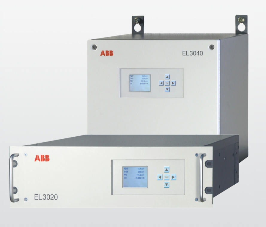
ABB EasyLine EL3000 Series Continuous gas analyzers
ABB EasyLine EL3000 Series Continuous gas analyzers
ABB EasyLine EL3000 Series Continuous gas analyzers
Measurement made easy
So smart, they're simple
—
A wide variety of measurement technology
• Detectors for multiple process and emission monitoring
applications
• Up to five sample components per device
• Suited for measuring flammable gases
• Version in IP rating II 3G for measuring non-flammable gases
• Performance-tested for emission monitoring in accordance
with EN 15267
• QAL3 monitoring in accordance with EN 14181 (optional)
—
Straightforward handling
• Automatic calibration including control of pump and valves
• Simplified calibration with air or integral calibration cells
eliminating the need for test gas cylinders
• Self-monitoring function indicates when maintenance is
required
—
Application-oriented design
• Housing design for 19-inch rack mounting or wall mounting
• Integrated gas feed as an option in model EL3020
• Ethernet, Modbus and PROFIBUS interfaces
• Configurable analog outputs and digital inputs and outputs
—
User-friendly operation
• Simple user interface
• Clear-text status messages
• Configuration of seldom required functions with
configuration software
Overview of the gas analyzers
Measuring technology (analyzers)
The following analyzers are available for selection:
• Uras26 infrared photometer for the measurement of infrared active gas components, e.g. CO, NO, SO2,
• Ultraviolet photometer Limas23 to measure NO, NO2 and SO2.
• Magnos206 oxygen analyzer for the measurement of
O2 in process gas or in N2,
• Magnos28 oxygen analyzer for the measurement of O2 in pro cess gas or in N2,
• Magnos27 oxygen analyzer for the measurement of O2 in flue
gas or in N2,
• The ZO23 trace oxygen analyzer is used for the measurement
of O2 in pure gases (N2, CO2, Ar).
• Caldos27 thermal conductivity analyzer for the measurement
of binary gas mixtures with different thermal conductivity, e.g.
Ar in O2, H2 in Ar, CH4 in N2
• Fidas24 flame-ionization detector for the measurement of hy drocarbons
• Electrochemical oxygen sensor for the measurement of O2
Magnos206 and Magnos28 can also be used in combination with
Uras26 or Limas23.
Magnos27 and Caldos27 can also be used in combination with
Uras26.
Magnos28 can also be used in combination with Magnos28.
Magnos28 can also be used in combination with Caldos27.
Caldos27 can also be used in combination with Caldos27.
Fidas24 and ZO23 cannot be used in combination with one of the
other analyzers.
The electrochemical oxygen sensor can only be used in combina tion with Uras26 or Limas23. Two electrochemical oxygen sen sors can be used in combination with Uras26 with separate gas
paths (only in model EL3020).
Each analyzer has one physical measurement range per sample
component. A section of the physical measurement range can be
mapped to the current output (analog output) by on-site config uration.
Calibration is always executed in the physical measurement
range. The permissible measurement range limits are given by
the specification of the smallest and largest measurement
ranges for the individual analyzers.
A total of up to five measurement components can be measured
with one gas analyzer.
Calibration
Calibration can be performed automatically or manually or exter nally controlled via the Modbus.
Automatic calibration – for all sample components together – is
normally started on a cyclically time-controlled basis; it can also
be started by an external control signal or via the Modbus as well
as manually on the display and operator control unit of the gas
analyzer.
Normally, simplified calibration methods with the built-in calibra tion cells or the so-called single-point calibration are used for au tomatic calibration. If calibration with test gases is required the
control of solenoid valves for switching on five test gases, zero
gas and sample gas via digital outputs can be configured.
Concept of operation
The functions required in normal operation are operated and con figured directly on the gas analyzer.
The device functions which are only seldom required, e.g. during
commissioning, are configured offline using the ECT configura tion program (‘EasyLine Configuration Tool’ on the enclosed DVD ROM) and then loaded into the gas analyzer.
QAL3 monitoring
The gas analyzer can optionally be equipped with QAL3 monitor ing, used to fulfill the requirements in accordance with EN 14181
for the storage and analysis of device adjustment data. The QAL3
monitoring option features the following functions:
• Automatic acquisition, verification and documentation of drift
and precision at zero and reference points
• Reporting via CUSUM and Shewhart control charts
• QAL3 data storage in the gas analyzer (maximum 1 year)
• QAL3 data display and read-out as well as parameter setting
via web browser
• Status messages on deviations beyond requirements
• Data export for further processing with spreadsheet programs
Electrical interfaces
The electrical interfaces for the output of measured values and
communication with external systems include
• The integrated Ethernet-10/100BASE-T interface for
– device configuration using the ECT configuration program
– QAL3 data transfer if the QAL3 monitoring option is integrated in the gas analyzer
– Data transmission using the Modbus TCP/IP protocol
(measured values, status signals, control signals)
as well as the integrated I/O modules depending on the functional range and order
• Profibus module with one RS485 and one MBP interface (also
in accordance with VDI 4201 Part 2),
• Modbus module with one RS232 and one RS485 interface (also
in accordance with VDI 4201 Part 3),
• Digital I/O module with four digital inputs and four digital outputs,
• 2-way analog output module with two analog outputs,
• 4-way analog output module with four analog outputs.
Integral gas feed
The integral gas feed (optional in model EL3020) is available in
two versions. It includes
• either the solenoid valve, pump, coarse filter, capillary tube
and flow sensor modules
• or the flow sensor module.
Housing design
The EL3020 gas analyzer model features a 19-inch housing with
3 height units (4 height units with Magnos27) and IP rating IP20
(IP40 in version for emissions monitoring).
The housing for the EL3040 gas analyzer model is designed as
wall-mount housing with degree of protection IP65.
Measurement principle
Non-dispersive infrared absorption
Photometer with 1 or 2 beam paths (gas paths) to measure up to
4 sample components
Sample components and measurement ranges
Sample components and smallest measurement ranges
sample component Smallest meas. range
CO 0…100 ppm
CO2 0…100 ppm
NO 0…150 ppm
SO2 0…100 ppm
N2O 0…100 ppm
CH4 0…100 ppm
Measurement range quantity
2 measurement ranges
Measurement range limits
Smallest meas. range Largest measurement range
0…100 ppm (NO: 0…150 ppm) 0…500 ppm (NO: 0…750 ppm)
0…200 ppm 0…1000 ppm
0…600 ppm 0…3000 ppm
0…2000 ppm 0…10000 ppm
0…0.6 vol.% 0…3 vol.%
0…2 vol.% 0…10 vol.%
0…6 vol.% 0…30 vol.%
0…20 vol.% 0…100 vol.%
An individual measurement range within the limits shown in the
table can be factory-set on special order.
Measurement ranges are freely adjustable within the limits shown
in the table.
Measurement ranges should not be set within ignition limits.
Version for use in air separation units
Only for binary gas mixtures consisting of the sample component
in Ar, N2 or O2
sample component Smallest/greatest measuring
range
CO 0…10 ppm / 0…50 ppm
CO2 0…5 ppm / 0…25 ppm
N2O 0…10 ppm / 0…50 ppm
CH4 0…20 ppm / 0…100 ppm
Other than the data valid for the standard version the following
data apply for this version (in % of the smallest measurement
range shown in the table):
Zero point drift: ≤ 1.5 % per day
Sensitivity drift: ≤ 1 % per week
Output signal fluctuation (2 σ): ≤ 0.5 % at T90 = 15 s
Temperature effect: ≤ 2 % per 10 °C
Stability
The following data only applies if all the influence variables (e.g.
flow, temperature and air pressure) are constant. They relate to
the smallest measurement range.
Linearity deviation
≤ 1 % of span
Repeatability
≤ 0.5 % of span
Zero point drift
≤ 1 % of span per week
Sensitivity drift
≤ 1 % of measured value per week
Output fluctuation (2 σ)
≤ 0.2 % of span at electronic T90 time (static/dynamic) = 5/0 sec
Detection limit (4 σ)
≤ 0.4 % of span at electronic T90 time (static/dynamic) = 5/0 sec
Influence effects
Flow effect
Flow rate in the 20…100 l/h range:
Associated gas effect/cross sensitivity
The knowledge of the sample gas composition is necessary for
the analyzer configuration. Selectivation measures to reduce the
associated gas effect (options): incorporation of interference fil ters or filter cells, internal electronic cross-sensitivity or carrier
gas correction for one sample component by other sample com ponents measured with the gas analyzer.
Temperature effect
Ambient temperature in the permissible range
– at zero point: ≤ 2 % of span per 10 °C
– on the sensitivity with thermostat effect:
≤ 3 % of the measured value per 10 °C
– on the sensitivity with thermostat effect (optional): ≤ 2 % of
the measured value per 10 °C
thermostat temperature = 55 °C
Air pressure effect
– at the zero point: no effect
– On sensitivity with pressure correction using an integrated
pressure sensor: ≤ 0.2 % of the measured value per 1 % of air
pressure change
The pressure sensor is located in the sample gas path if hoses are
used as the internal gas lines. If stainless-steel tubing is used for
internal gas lines the pressure sensor is routed to the outside via
a hose.
Power supply effect
Voltage and frequency in the permissible range; no effect
- YOKOGAWA
- Reliance
- ADVANCED
- SEW
- ProSoft
- WATLOW
- Kongsberg
- FANUC
- VSD
- DCS
- PLC
- man-machine
- Covid-19
- Energy and Gender
- Energy Access
- Renewable Integration
- Energy Subsidies
- Energy and Water
- Net zero emission
- Energy Security
- Critical Minerals
- A-B
- petroleum
- Mine scale
- Sewage treatment
- cement
- architecture
- Industrial information
- New energy
- Automobile market
- electricity
- Construction site
- HIMA
- ABB
- Rockwell
- Schneider Modicon
- Siemens
- xYCOM
- Yaskawa
- Woodward
- BOSCH Rexroth
- MOOG
- General Electric
- American NI
- Rolls-Royce
- CTI
- Honeywell
- EMERSON
- MAN
- GE
- TRICONEX
- Control Wave
- ALSTOM
- AMAT
- STUDER
- KONGSBERG
- MOTOROLA
- DANAHER MOTION
- Bentley
- Galil
- EATON
- MOLEX
- Triconex
- DEIF
- B&W
- ZYGO
- Aerotech
- DANFOSS
- KOLLMORGEN
- Beijer
- Endress+Hauser
- schneider
- Foxboro
- KB
- REXROTH
- YAMAHA
- Johnson
- Westinghouse
- WAGO
- TOSHIBA
- TEKTRONIX
- BENDER
- BMCM
- SMC
- HITACHI
- HIRSCHMANN
- XP POWER
- Baldor
- Meggitt
- SHINKAWA
- Other Brands
- UniOP
- KUKA
- IBA
- Beckhoff
51
-
ADLINK PCI-7433 - switch value acquisition card Isolated Digital Input Card
-
ADLINK PCI-9112 - 51-12252-0D20 Multi-Function Data Acquisition Card
-
ADLINK NUPRO-A301 REV:1.4 - industrial control motherboard PICMG Full-Size SBC
-
ADLINK 51-18502-0A10 - Frame Grabber Image Acquisition Interface Card
-
ADLINK PCI-7296 - 51-12009-0A50 PCB-I-E-925=6DX1 96-CH Parallel Digital I/O Board
-
ADLINK PCI-8132 GP A2 - Motion Control Card 2-Axis Servo & Stepper Controller
-
ADLINK PCI-7442 - switch quantity card data acquisition card 64-CH Isolated Card
-
ADLINK HPX-13S4 - baseboard PICMG 1.3 Passive Backplane Chassis Baseplate
-
ADLINK NuPRO-590 / NTC-567-ZM-F36 - Single Board Computer PCB-I-E-1853=9L21 Half-Size SBC
-
ADLINK PCIe-8332 - 16-axis plate Motion Control Hardware Card
-
ADLINK NuPRO-775 REV.B1 - motherboard Pentium 4 Full-Size PICMG SBC
-
ADLINK PXI-3920 - Embedded Controller 3U PXI cPCI System Intelligence Board
-
ADLINK PCI-8134 - driver card motion control card 4-Axis Controller Board
-
ADLINK HSL-DI32-M-N-011 / HSL-TB32-M-DIN - Digital Input & Base Module PLC Distributed I/O System
-
ADLINK PCI-6216V-206 / PCI-208V 009 - 16 CH 16bit analog output card
-
ADLINK NuPro-E330 - 51-41805-0A20 PCB Single Board Computer Host Board
-
ADLINK PCI-1622C - Card 8-Port RS-232/422/485 PCI Serial Communication Board
-
ADLINK PCIe-7432 - 51-18402-0A10 Carte PCIe Avec Plage D'Entrée Élevée Isolated DIO Card
-
ADLINK PCI-7250 - PCI Acquisition Card 8-CH Relay Output Isolated DI Card
-
ADLINK PCI-7230 - 32-CH Isolated Digital I/O Card
-
ADLINK PCI-8164 - PCB 4-Axis Motion Controller Card
-
ADLINK PCI-7854 - Collection card High-Speed Link Distributed Motion Controller
-
ADLINK NuPRO-935A/LV - industrial control computer motherboard Full-Size PICMG SBC
-
ADLINK IMB-M40H - motherboard IH61-AA4 1155 LGA1155 Micro-ATX Mainboard
-
ADLINK PCI-7248 - Linhua 51-12006-0A40 48-CH Parallel Digital I/O Card
-
ADLINK HPCI-14S12U - Linhua industrial computer baseboard Passive Backplane
-
ADLINK PCI-8132 Rev.A2 - 2-Axis Servo & Stepper Motion Controller Card
-
ADLINK ACL-8111 - ISA card Multi-Function DAQ Card
-
ADLINK ACL-8111 - ISA card Multi-Function Data Acquisition Board
-
ADLINK PCI-7200 REV.A3 - Digital I/O card 12MB/s High-Speed Parallel Digital I/O
-
ADLINK PCI-7296 REV.A3 - 96-CH High-Density Opto-Isolated DIO Card
-
ADLINK PCI-7434 - 64-CH Isolated Digital Output Card
-
ADLINK M-342 - atx motherboard Industrial PC Mainboard
-
ADLINK NuPRO-935ADV (A) 1.9 - CPU Board Intel Core 2 Quad CPU Q9500 2.83GHz PICMG Board
-
ADLINK NUPRO-935A/DV - motherboard dual network port 51-41802-0A10 CPU Board
-
ADLINK PCI-RTV24 - image capture card Analog Video Frame Grabber Board
-
ADLINK HPX-13S4 - device baseboard PICMG 1.3 Passive Backplane Chassis Baseplate
-
ADLINK PCI-8134A - control card 4-Axis Motion Controller Card
-
ADLINK ACL-7130 REV. B2 - industrial control capture card Isolated Digital I/O Board
-
ADLINK EBP-13E2 - Industrial Backplane Board Passive Backplane Baseboard
-
ADLINK NuPRO-935ADV (A) 1.9 - CPU Board Intel Core 2 Quad CPU Q9500 2.83GHz PICMG SBC
-
ADLINK PCI-8134A - motion control card 4-Axis Pulse-Train Controller Card
-
ADLINK PCI-9112 REV A.1 - Multi Function DA&C Board Data Acquisition Card
-
ADLINK 51-12001-0C20 - Circuit Board Multi-Function Data Acquisition Hardware
-
ADLINK PCI-7300A - 80-CH High-Speed Digital I/O Card
-
ADLINK PCI-7230 - 16-CH Isolated Digital Input Output Card
-
ADLINK DIN-814-GP - motion control module Interface Terminal Block
-
ADLINK NUPRO-A40H - 51-41807-1A20 Industrial Control Motherboard LGA1155
-
ADLINK PCI-7433 rev A2 - Isolated Digital Input Card
-
ADLINK NuPRO-780 - Pentium III 800 512 MB SBC NuPRO780 51-41309-0B2 Single Board Computer
-
ADLINK PCI-7853 / PCI-7854 - Acquisition card High-Speed Link Control Card
-
ADLINK NUPRO-852 / NUPRO-852LV - Industrial motherboard Full-Size PICMG CPU Board
-
ADLINK NuPRO-842LV/P - 51-41360-0B30 Industrial Motherboard Half-Size PICMG SBC
-
ADLINK PCI-FIW64 - 4/2 Channel IEEE1394B Image Capture Card Frame Grabber
-
ADLINK PCI-7851 Rev A1.1 - HSL system card High-Speed Link Master Controller
-
ADLINK PCI-7230 - 51-12003-0A50 card 32-CH Isolated Digital I/O Card
-
ADLINK NuPRO-841REV:1.0 - Industrial CPU Board Mainboard
-
ADLINK NuPRO-841 REV:1.0 - motherboard Industrial Control PC Mainboard
-
ADLINK PCI-8256 - 8-Axis Advanced Motion Control PCI Board
-
ADLINK PCI-6S / PCI6S - Backplane 6-Slot Passive Backplane Board
-
ADLINK PCI-7234 REV B3 - 32-CH Isolated Digital Output PCI Card
-
ADLINK PCI-8213 - HannStar MV-4 51-45003-0b4 Board
-
ADLINK PCI-7233 - 51-12004-0a20 board PCI7233 32-CH Isolated Digital Input Card
-
ADLINK PCI-7851 - 006 51-24003-0B20 High-Speed Link Master Motion Control Card
-
ADLINK PCI-7432 - 64-CH Isolated Digital I/O PCI Cards
-
ADLINK LPCI-3488 - Card Low Profile IEEE-488 GPIB Interface Card
-
ADLINK HPCI14S REV.B1 - industrial control computer base plate Passive Backplane
-
ADLINK NEON-1020 - Industrial camera Smart Camera Vision System
-
ADLINK PCI-7432 - Isolated Digital I/O PCI Card 64-CH
-
ADLINK Pcm-7250+ - 8-Ch Relay Outputs & 8-Ch Isolated DI Module PC/104
-
ADLINK CPCI-7841 - DUAL-PORT ISOLATED CAN INTERFACE CARD CompactPCI
-
ADLINK PCI-3488 / PCI-GPIB - PCI IEEE-488 GPIB Interface Card
-
ADLINK PCI-1711U - Card Multi-Function Data Acquisition Board
-
ADLINK NUPRO-A301 - REV:1.1 1.2 1.4 PICMG Full-Size Single Board Computer
-
Adlink DIN-50S-01 - PLOTECH 51-14024-0A40 50-pin Wiring Terminal Board
-
Chroma 52962 / 58183 - PXI Optical Spectrometer carrier adapter Card
-
ADLINK PCI-6208V - PCI DATA ACQUISITION & RECORDING CARD 8-CH Analog Output
-
ADLINK HSL-DI32-DB-N - Industrial Control Board Distributed Digital Input Module
-
ADLINK HSL-AO4-U - 4-CH HIGH SPEED LINK ANALOG OUTPUT MODULE Distributed I/O
-
ADLINK PCI-7396 - 0050 GP 51-12012-0B20 96-CH High-Speed Digital I/O Card
-
ADLINK NUPRO-935A/DV - 51-41802-0A10 motherboard Industrial CPU Single Board Computer
-
ADLINK PCI-9111 DG - Industrial Acquisition Card Multi-Function DAQ Card
-
ADLINK NuPRO-E315 - industrial computer motherboard Intel Atom SHB SBC
-
ADLINK NUPRO-406 REV:B1 - Industrial Control Motherboard Full-Size PICMG CPU Board
-
ADLINK NuPRO-E330 - motherboard Industrial Control System Host Board PICMG 1.3
-
ADLINK ACL-6128A 103 - 51-11002-1A4 2-CH Isolated Analog Output Card
-
XTRAMUS cPS-H325/AC - POWER SUPPLY NUSTREAMS 600 NETWORK TESTING EQUIPMENT Power Module
-
ADLINK DIN-814P-A4 - 51-14056-0A10 Terminal Block Motion Control Breakout Board
-
ADLINK TB-24P/24-01 - 24-Channel Card Terminal Breakout Board
-
ADLINK PCI-7251 - 51-12008-0A30 PCI7251 8-CH Relay Output Isolated Digital Input Card
-
ADLINK HSL-TB64-DIN REV A1 / HSL-DO32-DB-N - 2ea Board Breakout Terminal Board Distributed I/O Module
-
ADLINK NuPRO-865 REV 3.0 - industrial computer motherboard Full-Size PICMG SBC
-
ADLINK NUPRO-A40H - motherboard 51-41807-1A30 OSP H61 Industrial PC Mainboard
-
ADLINK LPCI-3488A - PCI Card 51-12801-0A30 GPIB Interface Card
-
ADLINK DIN-825-4P0 - 51-14085-0A30 Terminal Printed Circuit Board Breakout Block
-
ADLINK IMB-T10/D2550 V - MOTHER BOARD 80-PXG160-A1A01 IMB-T10-M2G-S32G Industrial Mainboard
-
ADLINK PCI-8144N - Motion Control card Stepper Motor Controller
-
ADLINK PCI-7433 - Digital acquisition card Isolated Digital Input Card
-
ADLINK PCI-9112 DG - Data Acquisition card 51-12252-0D20 Multi-Function DAQ
-
ADLINK IMB-M40H - motherboard IH61-AA4 1155 LGA1155 Micro-ATX Mainboard
-
ADLINK TB-24P/24-01 - Carte 24 voies Terminal Breakout Board Connector Module
-
ADLINK HSL-D16DO16-M-NN - Distributed Discrete Input Output I/O Module
-
ADLINK PCI-7248 - PCI CARD 51-12006-0A40 48-CH Parallel Digital I/O Board
-
ADLINK HSL-DI32-DB-N - Industrial Control Board Distributed I/O Digital Input Module
-
ADLINK PCI-7433 - Pci 7433 Isolated Digital Input Card
-
ADLINK PCI-6208V - 008 Data acquisition card 8-CH Analog Output Card
-
ADLINK IH61-AA4 - industrial motherboard LGA1155 Micro-ATX Mainboard
-
ADLINK PXI-3920 - PXI 3U cPCI Industrial Controller Embedded System CPU Board
-
ADLINK PCI-6308 - Analog Output DAQ Card Isolated Voltage Output Card
-
ADLINK PCI-7200 - data acquisition card REV.A3 High-Speed Parallel DIO Card
-
ADLINK NuPRO-E315 - Industrial Control Computer Motherboard PICMG 1.3 SHB SBC
-
ADLINK PCI-1610C - Card 4-Port Isolated RS-232 PCI Serial Communication Card
-
ADLINK PCI-1716 - Card High-Resolution Multi-Function DAQ Card
-
ADLINK MI-965 - Industrial Mini-ITX Motherboard CPU Board
-
ADLINK PCI-1610A - Card 4-Port RS-232 PCI Serial Communication Card
-
ADLINK cBP-3208/3208R - CPCI Board 3U 8-Slot CompactPCI Backplane
-
ADLINK PCI-8134A - 51-12421-0A10 4-Axis Motion Controller Card
-
ADLINK PCI-8164 - Motion Control Card 4-Axis Advanced Controller Card
-
ADLINK NUPRO-935A/DV - motherboard dual network port 51-41802-0A10 CPU Board
-
ADLINK PCI-7248 - 51-12006-0A40 acquisition card 48-CH Parallel DIO Card
-
ADLINK PCI-7443 - 51-12022-0A10 BOARD 128-CH Isolated Digital Input Card
-
ADLINK DIN-825-GP4 - Terminal Block Interface Board Breakout Module
-
ADLINK PCI-7248 - Card 48-CH Parallel Digital I/O Card
-
ADLINK NUPRO-865 REV :3.0 - industrial motherboard Intel Pentium 4 CPU Board
-
ADLINK PCI-9113A - Isolated Analog Input Data Acquisition Card
-
ADLINK HPCI-8S4 - REV.B2 Industrial Control Base Plate Passive Backplane
-
ADLINK M-342 - atx motherboard Industrial PC Mainboard
-
ADLINK PCI-RTV24 - image capture card Analog Video Frame Grabber Board

K-JIANG

Add: Jimei North Road, Jimei District, Xiamen, Fujian, China
Tell:+86-15305925923