
K-WANG
+086-15305925923
Service expert in industrial control field!


Product
Article
NameDescriptionContent
Adequate Inventory, Timely Service
pursuit of excellence


Ship control system
Equipment control system
Power monitoring system
Current position:
新闻动态
newS
Brand
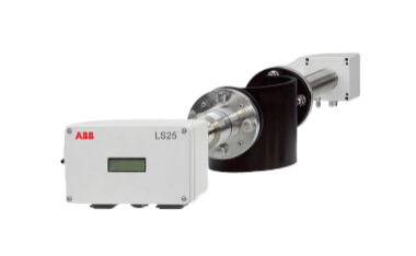
ABB AO2000 Advance Optima Continuous gas analyzers
ABB AO2000 Advance Optima Continuous gas analyzers
ABB AO2000 Advance Optima Continuous gas analyzers
DescriptionApplication Information from the AO2000 gas analyzer can be transferred to a PC or DCS via
the Modbus. Measurement values, status signals and also signals of analog and
digital inputs and outputs are thus available for further usage.
Using the AO-MDDE server the signals can be integrated into standard software
(e.g. Excel, Visual Basic or LabVIEW). For further information, see Chapter 4
“AO-MDDE server and demo programs”, page 3535. AO-MDDE can be
downloaded from the DVD-ROM which is delivered together with each gas
analyzer. AO-MDDE does not support Modbus over TCP/IP.
Basic documents Modbus Application Protocol Specification V1.1b, December 28, 2006
Modbus over Serial Line Specification and Implementation Guide V1.02,
December 20, 2006
Modbus Messaging on TCP/IP Implementation Guide V1.0b, October 24, 2006
These documents are available at http://www.modbus.org/specs.php.
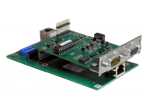
Interfaces and
connection versions
The RS232 and the RS485 interface located on the RS232/RS485 module in
AO2000 are supported, where only one can be operated at a time. Connection
versions are described in Chapter 3 “Modbus connection”, page 30.
As an alternative, the Ethernet 10/100BASE-T interface can be used for data
transmission via Modbus TCP/IP protocol (from software version 5.1, see page 7).
Transferred data Read Write Example
Measurement values x – CO, NO, H2, etc.
Analog inputs x – Indication of mA-values of external analyzers
Analog outputs x – Indication of mA-values of measurement values or calculated
values (function block application)
Digital inputs x – Indication of external status signals
Digital outputs x – Measurement range feedback, indication of solenoid or pump
controls
Bus analog inputs x x Entering analog values into the function block application
Bus analog outputs x – Outputting analog values from the function block application
Bus digital inputs x x Control of functions such as auto calibration, measuring range
control, etc. after function block configuration
Bus digital outputs x – Indication of all functions integrated by function block configuration such as alarm signaling etc.
Modbus configuration x – Indication how many components, AOs, DOs, etc. have been
configured or are in the gas analyzer
Status signals x – Indication of failure, maintenance mode, maintenance request
Measurement range
feedback
x – Index of the active measurement range
Measurement range
configuration
x – Measurement range limits (start and end value)
Measurement range
drift values
x – Offset drift, amplification drift, delta offset drift, delta amplification
drift
QAL3 calibration data x – Setpoints and actual values, measuring range and date of last
calibration (not available in analyzer modules Limas11, Uras14,
Magnos16, Magnos106, Caldos15, Caldos17, and MultiFID14)
Data transfer For data transfer a combination of frames is used, that consists of 1/0 information,
united to one or more telegrams.
Frame The transfer values are decomposed in bytes (= 8 bit). Each of these bytes is
completed by one start-bit, possibly one parity-bit (even number of “1”) and one
stop-bit. In the following description the term “byte” will be used, even if ten or
eleven bits will be transferred including the start-, stop- and parity-bits.
Telegrams The Modbus telegrams consist of the following frames:
address (1 byte), function (1 byte), data (n bytes) and check sum (2 bytes).
The telegrams also take on the “shake-hands-function”: each telegram from
master to slave must be responded, before a new telegram is allowed to be
transmitted. The computer has to have in a adequate supervision, for excluding
non answering bus participants (time-out-supervision).
Admissible addresses As addresses for the participants of the bus the numbers 1 to 255 are admitted.
The address 0 is the global address (broadcast-address). When this address will
be used in a telegram, all participants accept this telegram without an acknowledg ment to the master.
Functions Code Term Function
01 Read coil status Reading of binary values of type coil
02 Read input status Reading of binary values of type status
03 Read holding registers Reading of 16 bit holding-registers
04 Read input registers Reading of 16 bit input-registers
05 Force single coil Setting of a single binary value
06 Preset single register Set of a single 16 bit-register; for DINT or
REAL two telegrams are necessary
08 Loopback diagnostic test Testing telegram for diagnostics of the
communication capability of slave
15 Force multiple coils Set of several successive binary values
16 Preset multiple registers Set of several successive 16 bit-registers
Check sum The check sum is calculated over all bytes of one telegram without the start-,
stop- and parity-bits.
Transfer rules The neutral position of the data line corresponds with the logical “1”.
A distance of more than 3.5 bytes, however at least 10 ms is defined as separation
between two telegrams. For the beginning of the data transfer the neutral position
of the data line must be observed.
Integration The AO2000 Modbus/TCP server expects requests from the current IP addresses
via the communication port. A maximum of 4 clients can be connected to the
Modbus/TCP server of an AO2000 at the same time. If the connection to a client
breaks down, the connection status in the Modbus/TCP server is enabled again
after a max. 60 seconds.
Reading out data
from the AO2000
Modbus/TCP server
The following procedure must be executed on the Modbus client, in order to
receive data from the AO2000 Modbus/TCP server:
1. Establish a TCP connection to port 502 on the server.
2. Create a Modbus request.
3. Send the Modbus request incl. the Modbus/TCP MBAP Header.
4. Wait for a response to the same TCP connection.
5. Read the first 6 bytes of the response; these state the length of the response.
6. Read the remaining bytes of the response.
Functions, addresses
and registers
The supported functions and the addresses and registers of Modbus over TCP/IP
are equivalent to those of Modbus over RS232/RS485.
Function code 43 with MEI 14 (MEI = Modbus Encapsulated Interface) is used to
read the device parameters to
read measured values,
transfer simulation data,
apply reference material.
Address assignment
of the device
parameters for the
function code 43
There is read access to the device parameters.
Measurement components are mapped with the following structure:
Name
Measurement range start
Measurement range end
Unit
The number of the first measured values register is listed under BasisM in the
device parameters list.
The measured value status is implemented as NAMUR status:
Bit Assignmant
0 Error
1 Maintenance
2 Maintenance request
3 Beyond specification
4 Test operation, simulation measured value transmitted
5…15 Reserved for extensions
16…31 Vendor-specific
The number of the first simulation data register is listed under BasisS in the device
parameters list.
The number of the register to apply reference material is listed under BasisR in the
device parameters list. Maximum 32 Bus DIs are reserved for transferring
reference material.
The register "status of application" is used for feedback of the DIs for which a
hardware digital output is connected. When reference material is applied, the
status "maintenance" is set and a message is displayed on the gas analyzer's
screen.
Name Object ID Encoding Table Attribute Description
VendorName 0x00 String System_control Fabrication_number Manufacturer name
ProductCode 0x01 String System_control Product_Code Manufacturerspecific device
identifier
MajorMinorRevision 0x02 String System_control Version Software version of
measuring system
ProductName 0x04 String System_control Product_Name Device name
SerialNumber 0x80 String System_control SerialNumber Serial number of
measuring system
ComponentNumber 0x81 Word Detector_para Classification = 0 Number of
measurands
BasisM 0x82 Word Modbus_conf Registernumber First register of the
measurands block
BasisS 0x83 Word Modbus_conf Registernumber First register of the
simulation data
BasisR 0x84 Word Modbus_conf Registernumber First register of the
reference material
data
Component1_Name 0x85 String Component_para Name Name of measured
component 1
Component1_
Range_Start
0x86 Float Meas_range_para Lower_meas_range Lower limit of output
range of measured
component 1
Component1_
Range_End
0x87 Float Meas_range_para Upper_meas_range Upper limit of output
range of measured
component 1
Component1_Unit 0x88 String Component_para Unit_name Unit of measured
component 1
Component2_Name 0x89 String Component_para Name Name of measured
component 2
Component2_
Range_Start
0x8A Float Meas_range_para Lower_meas_range Lower limit of output
range of measured
component 2
Component2_
Range_End
0x8B Float Meas_range_para Upper_meas_range Upper limit of output
range of measured
component 2
Component2_Unit 0x8C String Component_para Unit_name Unit of measured
component 2
- YOKOGAWA
- Reliance
- ADVANCED
- SEW
- ProSoft
- WATLOW
- Kongsberg
- FANUC
- VSD
- DCS
- PLC
- man-machine
- Covid-19
- Energy and Gender
- Energy Access
- Renewable Integration
- Energy Subsidies
- Energy and Water
- Net zero emission
- Energy Security
- Critical Minerals
- A-B
- petroleum
- Mine scale
- Sewage treatment
- cement
- architecture
- Industrial information
- New energy
- Automobile market
- electricity
- Construction site
- HIMA
- ABB
- Rockwell
- Schneider Modicon
- Siemens
- xYCOM
- Yaskawa
- Woodward
- BOSCH Rexroth
- MOOG
- General Electric
- American NI
- Rolls-Royce
- CTI
- Honeywell
- EMERSON
- MAN
- GE
- TRICONEX
- Control Wave
- ALSTOM
- AMAT
- STUDER
- KONGSBERG
- MOTOROLA
- DANAHER MOTION
- Bentley
- Galil
- EATON
- MOLEX
- Triconex
- DEIF
- B&W
- ZYGO
- Aerotech
- DANFOSS
- KOLLMORGEN
- Beijer
- Endress+Hauser
- schneider
- Foxboro
- KB
- REXROTH
- YAMAHA
- Johnson
- Westinghouse
- WAGO
- TOSHIBA
- TEKTRONIX
- BENDER
- BMCM
- SMC
- HITACHI
- HIRSCHMANN
- XP POWER
- Baldor
- Meggitt
- SHINKAWA
- Other Brands
- UniOP
- KUKA
- IBA
- Beckhoff
51
-
ADLINK PCI-7433 - switch value acquisition card Isolated Digital Input Card
-
ADLINK PCI-9112 - 51-12252-0D20 Multi-Function Data Acquisition Card
-
ADLINK NUPRO-A301 REV:1.4 - industrial control motherboard PICMG Full-Size SBC
-
ADLINK 51-18502-0A10 - Frame Grabber Image Acquisition Interface Card
-
ADLINK PCI-7296 - 51-12009-0A50 PCB-I-E-925=6DX1 96-CH Parallel Digital I/O Board
-
ADLINK PCI-8132 GP A2 - Motion Control Card 2-Axis Servo & Stepper Controller
-
ADLINK PCI-7442 - switch quantity card data acquisition card 64-CH Isolated Card
-
ADLINK HPX-13S4 - baseboard PICMG 1.3 Passive Backplane Chassis Baseplate
-
ADLINK NuPRO-590 / NTC-567-ZM-F36 - Single Board Computer PCB-I-E-1853=9L21 Half-Size SBC
-
ADLINK PCIe-8332 - 16-axis plate Motion Control Hardware Card
-
ADLINK NuPRO-775 REV.B1 - motherboard Pentium 4 Full-Size PICMG SBC
-
ADLINK PXI-3920 - Embedded Controller 3U PXI cPCI System Intelligence Board
-
ADLINK PCI-8134 - driver card motion control card 4-Axis Controller Board
-
ADLINK HSL-DI32-M-N-011 / HSL-TB32-M-DIN - Digital Input & Base Module PLC Distributed I/O System
-
ADLINK PCI-6216V-206 / PCI-208V 009 - 16 CH 16bit analog output card
-
ADLINK NuPro-E330 - 51-41805-0A20 PCB Single Board Computer Host Board
-
ADLINK PCI-1622C - Card 8-Port RS-232/422/485 PCI Serial Communication Board
-
ADLINK PCIe-7432 - 51-18402-0A10 Carte PCIe Avec Plage D'Entrée Élevée Isolated DIO Card
-
ADLINK PCI-7250 - PCI Acquisition Card 8-CH Relay Output Isolated DI Card
-
ADLINK PCI-7230 - 32-CH Isolated Digital I/O Card
-
ADLINK PCI-8164 - PCB 4-Axis Motion Controller Card
-
ADLINK PCI-7854 - Collection card High-Speed Link Distributed Motion Controller
-
ADLINK NuPRO-935A/LV - industrial control computer motherboard Full-Size PICMG SBC
-
ADLINK IMB-M40H - motherboard IH61-AA4 1155 LGA1155 Micro-ATX Mainboard
-
ADLINK PCI-7248 - Linhua 51-12006-0A40 48-CH Parallel Digital I/O Card
-
ADLINK HPCI-14S12U - Linhua industrial computer baseboard Passive Backplane
-
ADLINK PCI-8132 Rev.A2 - 2-Axis Servo & Stepper Motion Controller Card
-
ADLINK ACL-8111 - ISA card Multi-Function DAQ Card
-
ADLINK ACL-8111 - ISA card Multi-Function Data Acquisition Board
-
ADLINK PCI-7200 REV.A3 - Digital I/O card 12MB/s High-Speed Parallel Digital I/O
-
ADLINK PCI-7296 REV.A3 - 96-CH High-Density Opto-Isolated DIO Card
-
ADLINK PCI-7434 - 64-CH Isolated Digital Output Card
-
ADLINK M-342 - atx motherboard Industrial PC Mainboard
-
ADLINK NuPRO-935ADV (A) 1.9 - CPU Board Intel Core 2 Quad CPU Q9500 2.83GHz PICMG Board
-
ADLINK NUPRO-935A/DV - motherboard dual network port 51-41802-0A10 CPU Board
-
ADLINK PCI-RTV24 - image capture card Analog Video Frame Grabber Board
-
ADLINK HPX-13S4 - device baseboard PICMG 1.3 Passive Backplane Chassis Baseplate
-
ADLINK PCI-8134A - control card 4-Axis Motion Controller Card
-
ADLINK ACL-7130 REV. B2 - industrial control capture card Isolated Digital I/O Board
-
ADLINK EBP-13E2 - Industrial Backplane Board Passive Backplane Baseboard
-
ADLINK NuPRO-935ADV (A) 1.9 - CPU Board Intel Core 2 Quad CPU Q9500 2.83GHz PICMG SBC
-
ADLINK PCI-8134A - motion control card 4-Axis Pulse-Train Controller Card
-
ADLINK PCI-9112 REV A.1 - Multi Function DA&C Board Data Acquisition Card
-
ADLINK 51-12001-0C20 - Circuit Board Multi-Function Data Acquisition Hardware
-
ADLINK PCI-7300A - 80-CH High-Speed Digital I/O Card
-
ADLINK PCI-7230 - 16-CH Isolated Digital Input Output Card
-
ADLINK DIN-814-GP - motion control module Interface Terminal Block
-
ADLINK NUPRO-A40H - 51-41807-1A20 Industrial Control Motherboard LGA1155
-
ADLINK PCI-7433 rev A2 - Isolated Digital Input Card
-
ADLINK NuPRO-780 - Pentium III 800 512 MB SBC NuPRO780 51-41309-0B2 Single Board Computer
-
ADLINK PCI-7853 / PCI-7854 - Acquisition card High-Speed Link Control Card
-
ADLINK NUPRO-852 / NUPRO-852LV - Industrial motherboard Full-Size PICMG CPU Board
-
ADLINK NuPRO-842LV/P - 51-41360-0B30 Industrial Motherboard Half-Size PICMG SBC
-
ADLINK PCI-FIW64 - 4/2 Channel IEEE1394B Image Capture Card Frame Grabber
-
ADLINK PCI-7851 Rev A1.1 - HSL system card High-Speed Link Master Controller
-
ADLINK PCI-7230 - 51-12003-0A50 card 32-CH Isolated Digital I/O Card
-
ADLINK NuPRO-841REV:1.0 - Industrial CPU Board Mainboard
-
ADLINK NuPRO-841 REV:1.0 - motherboard Industrial Control PC Mainboard
-
ADLINK PCI-8256 - 8-Axis Advanced Motion Control PCI Board
-
ADLINK PCI-6S / PCI6S - Backplane 6-Slot Passive Backplane Board
-
ADLINK PCI-7234 REV B3 - 32-CH Isolated Digital Output PCI Card
-
ADLINK PCI-8213 - HannStar MV-4 51-45003-0b4 Board
-
ADLINK PCI-7233 - 51-12004-0a20 board PCI7233 32-CH Isolated Digital Input Card
-
ADLINK PCI-7851 - 006 51-24003-0B20 High-Speed Link Master Motion Control Card
-
ADLINK PCI-7432 - 64-CH Isolated Digital I/O PCI Cards
-
ADLINK LPCI-3488 - Card Low Profile IEEE-488 GPIB Interface Card
-
ADLINK HPCI14S REV.B1 - industrial control computer base plate Passive Backplane
-
ADLINK NEON-1020 - Industrial camera Smart Camera Vision System
-
ADLINK PCI-7432 - Isolated Digital I/O PCI Card 64-CH
-
ADLINK Pcm-7250+ - 8-Ch Relay Outputs & 8-Ch Isolated DI Module PC/104
-
ADLINK CPCI-7841 - DUAL-PORT ISOLATED CAN INTERFACE CARD CompactPCI
-
ADLINK PCI-3488 / PCI-GPIB - PCI IEEE-488 GPIB Interface Card
-
ADLINK PCI-1711U - Card Multi-Function Data Acquisition Board
-
ADLINK NUPRO-A301 - REV:1.1 1.2 1.4 PICMG Full-Size Single Board Computer
-
Adlink DIN-50S-01 - PLOTECH 51-14024-0A40 50-pin Wiring Terminal Board
-
Chroma 52962 / 58183 - PXI Optical Spectrometer carrier adapter Card
-
ADLINK PCI-6208V - PCI DATA ACQUISITION & RECORDING CARD 8-CH Analog Output
-
ADLINK HSL-DI32-DB-N - Industrial Control Board Distributed Digital Input Module
-
ADLINK HSL-AO4-U - 4-CH HIGH SPEED LINK ANALOG OUTPUT MODULE Distributed I/O
-
ADLINK PCI-7396 - 0050 GP 51-12012-0B20 96-CH High-Speed Digital I/O Card
-
ADLINK NUPRO-935A/DV - 51-41802-0A10 motherboard Industrial CPU Single Board Computer
-
ADLINK PCI-9111 DG - Industrial Acquisition Card Multi-Function DAQ Card
-
ADLINK NuPRO-E315 - industrial computer motherboard Intel Atom SHB SBC
-
ADLINK NUPRO-406 REV:B1 - Industrial Control Motherboard Full-Size PICMG CPU Board
-
ADLINK NuPRO-E330 - motherboard Industrial Control System Host Board PICMG 1.3
-
ADLINK ACL-6128A 103 - 51-11002-1A4 2-CH Isolated Analog Output Card
-
XTRAMUS cPS-H325/AC - POWER SUPPLY NUSTREAMS 600 NETWORK TESTING EQUIPMENT Power Module
-
ADLINK DIN-814P-A4 - 51-14056-0A10 Terminal Block Motion Control Breakout Board
-
ADLINK TB-24P/24-01 - 24-Channel Card Terminal Breakout Board
-
ADLINK PCI-7251 - 51-12008-0A30 PCI7251 8-CH Relay Output Isolated Digital Input Card
-
ADLINK HSL-TB64-DIN REV A1 / HSL-DO32-DB-N - 2ea Board Breakout Terminal Board Distributed I/O Module
-
ADLINK NuPRO-865 REV 3.0 - industrial computer motherboard Full-Size PICMG SBC
-
ADLINK NUPRO-A40H - motherboard 51-41807-1A30 OSP H61 Industrial PC Mainboard
-
ADLINK LPCI-3488A - PCI Card 51-12801-0A30 GPIB Interface Card
-
ADLINK DIN-825-4P0 - 51-14085-0A30 Terminal Printed Circuit Board Breakout Block
-
ADLINK IMB-T10/D2550 V - MOTHER BOARD 80-PXG160-A1A01 IMB-T10-M2G-S32G Industrial Mainboard
-
ADLINK PCI-8144N - Motion Control card Stepper Motor Controller
-
ADLINK PCI-7433 - Digital acquisition card Isolated Digital Input Card
-
ADLINK PCI-9112 DG - Data Acquisition card 51-12252-0D20 Multi-Function DAQ
-
ADLINK IMB-M40H - motherboard IH61-AA4 1155 LGA1155 Micro-ATX Mainboard
-
ADLINK TB-24P/24-01 - Carte 24 voies Terminal Breakout Board Connector Module
-
ADLINK HSL-D16DO16-M-NN - Distributed Discrete Input Output I/O Module
-
ADLINK PCI-7248 - PCI CARD 51-12006-0A40 48-CH Parallel Digital I/O Board
-
ADLINK HSL-DI32-DB-N - Industrial Control Board Distributed I/O Digital Input Module
-
ADLINK PCI-7433 - Pci 7433 Isolated Digital Input Card
-
ADLINK PCI-6208V - 008 Data acquisition card 8-CH Analog Output Card
-
ADLINK IH61-AA4 - industrial motherboard LGA1155 Micro-ATX Mainboard
-
ADLINK PXI-3920 - PXI 3U cPCI Industrial Controller Embedded System CPU Board
-
ADLINK PCI-6308 - Analog Output DAQ Card Isolated Voltage Output Card
-
ADLINK PCI-7200 - data acquisition card REV.A3 High-Speed Parallel DIO Card
-
ADLINK NuPRO-E315 - Industrial Control Computer Motherboard PICMG 1.3 SHB SBC
-
ADLINK PCI-1610C - Card 4-Port Isolated RS-232 PCI Serial Communication Card
-
ADLINK PCI-1716 - Card High-Resolution Multi-Function DAQ Card
-
ADLINK MI-965 - Industrial Mini-ITX Motherboard CPU Board
-
ADLINK PCI-1610A - Card 4-Port RS-232 PCI Serial Communication Card
-
ADLINK cBP-3208/3208R - CPCI Board 3U 8-Slot CompactPCI Backplane
-
ADLINK PCI-8134A - 51-12421-0A10 4-Axis Motion Controller Card
-
ADLINK PCI-8164 - Motion Control Card 4-Axis Advanced Controller Card
-
ADLINK NUPRO-935A/DV - motherboard dual network port 51-41802-0A10 CPU Board
-
ADLINK PCI-7248 - 51-12006-0A40 acquisition card 48-CH Parallel DIO Card
-
ADLINK PCI-7443 - 51-12022-0A10 BOARD 128-CH Isolated Digital Input Card
-
ADLINK DIN-825-GP4 - Terminal Block Interface Board Breakout Module
-
ADLINK PCI-7248 - Card 48-CH Parallel Digital I/O Card
-
ADLINK NUPRO-865 REV :3.0 - industrial motherboard Intel Pentium 4 CPU Board
-
ADLINK PCI-9113A - Isolated Analog Input Data Acquisition Card
-
ADLINK HPCI-8S4 - REV.B2 Industrial Control Base Plate Passive Backplane
-
ADLINK M-342 - atx motherboard Industrial PC Mainboard
-
ADLINK PCI-RTV24 - image capture card Analog Video Frame Grabber Board

K-JIANG

Add: Jimei North Road, Jimei District, Xiamen, Fujian, China
Tell:+86-15305925923