
K-WANG


Cooper Crouse Hinds EVLS HAZARD-GARD Explosion proof Lamp Installation and Maintenance
Cooper Crouse Hinds EVLS HAZARD-GARD Explosion proof Lamp Installation and Maintenance
Scope of application and core protection characteristics
Adaptation of Hazardous Areas and Environment
Specific scope of adaptation category
Hazardous Area Classification 1: Class I Division 1 (Groups B/GB, C, D); 2. Class I Zone 1 (Group IIB+H2, with GB suffix); 3. Class II and Class III zones; 4. There are multiple types of hazardous environments present simultaneously
Environmental type: humid environment (compliant with UL1598), marine environment (compliant with UL1598A)
Protection level Type 4X (anti-corrosion, dustproof, splash proof), IP66 (completely dustproof, strong waterproof)
Key Usage Restrictions
Environmental temperature: shall not exceed the maximum environmental temperature indicated on the lamp nameplate, and the operating temperature (T code) shall not exceed the ignition temperature of the hazardous environment;
Installation posture: The lamp holder must be facing upwards and the angle with the vertical direction should not exceed 25 °;
Sealing requirements: All sealing gaskets must be clean and undamaged, and the threads must be fully engaged to ensure explosion-proof integrity;
Light source limitation: Only use lamps of the type and power specified on the nameplate, and do not mix other specifications.
Core Product Parameters
Category specific parameters
Voltage specifications can be selected as 120V/208V/220V/240V/277V/480V, supporting three tap and multi tap configurations (default 277V at the factory)
Light source parameter types: High pressure sodium lamp (HPS), metal halide lamp (MH); Power: 50W, 70W, 100W, 150W, 175W; Lamp holder: Only medium-sized lamp holders
Optional functions include ballast protection (catalog suffix BG, only HPS 50-150W), fast reignition (catalog suffix IR, only HPS 50-150LX W), fuse (catalog suffix S658, only MH 175W)
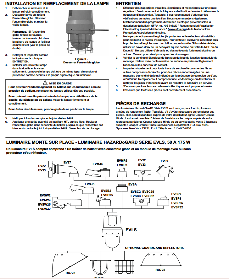
The complete structure of the lighting fixture includes: ballast lamp housing, installation module, (optional) protective cover/reflector
Installation specifications and procedures
Preparation before installation
Personnel requirements: Only qualified electricians are allowed to operate and must be familiar with NEC Article 501 (CEC Section 18) and local electrical regulations;
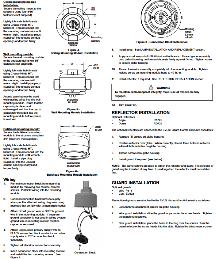
Tools and materials: Corresponding specifications of fasteners need to be prepared (4 5/16 "fasteners for ceiling installation, 2 3/8" fasteners for wall/bulkhead, not included), Crouse Hinds HTL lubricant, and power cables that meet temperature ratings;
Safety prerequisite: The power must be disconnected throughout the installation/maintenance process to ensure that the lighting fixture is cooled before operation.
Installation module and fixing requirements
The product provides 5 installation modules, with unified core installation requirements:
Thread lubrication: All installation module threads should be lightly coated with HTL lubricant to prevent biting and jamming;
Conduit sealing: Complete the conduit sealing according to the requirements in Table 1 to avoid the risk of explosion;
|Installation module combination | Group C&D sealing distance | Group B sealing distance|
|EVSA adapter+EV ceiling installation | 5 feet (1.5m) | 18 inches (45cm)|
|EVSJ Column Installation | - | 10 Feet (3m)|
|EVSA adapter+EVMJ column installation | - | 18 inches (45cm)|
|EVSA adapter+EV wall bracket | - | 18 inches (45cm)|
|EVSA adapter+EVJ bulkhead installation | - | Not applicable|
Fixed torque: The wheel hub locking screw needs to be tightened to a torque of 40 pounds inches;
Idle opening: Unused conduit openings must be equipped with accompanying plugs and secured.
Wiring process (key steps)
Dismantling the junction box: unscrew 2 chrome plated screws and remove the junction box;
Wiring: Introduce on-site cables into the installation module;
Grounding connection: Connect the circuit grounding wire to the green grounding wire of the installation module; If the wiring system does not have an independent grounding wire, the module grounding wire should be capped or removed;
Power connection: Connect the ungrounded main power supply line to the black wire in the junction box, and connect the other power supply line to the red wire;
Voltage adaptation: The default voltage at the factory is 277V. When other voltages are required, disconnect the ballast 277V lead, connect the target voltage lead, and seal the 277V lead with a crimping connector;
Fixed and reset: Tighten all electrical connections, put the junction box back into the installation module, and tighten the screws;
Lamp assembly: Apply HTL lubricant to the thread of the lampshade, screw it tightly to the O-ring, and tighten the fixing screws; Fully screw the lamp into the installation module and tighten the locking screw (40 pound inch);
Optional accessory installation: Reflector (RA725 angular/RD725 spherical) and protective cover (P515 metal wire/EV502 cast) need to be installed in the order of "reflector first, protective cover later", using a total of 3 fixing screws.
Maintenance and Replacement
Maintenance cycle and content
Cycle requirement: At least once a year, the specific frequency should be adjusted according to the usage environment and frequency. It is recommended to follow NFPA 70B "Recommended Practice for Electrical Equipment Maintenance";
Core maintenance items:
Cleaning: Use a clean damp cloth to wipe the lampshade, protective cover, and reflector. For stubborn stains, use mild soap or Collinite NCF, Duco # 7 cleaner. Do not use abrasives or strong acid/alkali cleaners;
Electrical inspection: Check the electrical continuity of the contact ring of the junction box, lightly polish to remove surface contaminants; Ensure that all connections are clean and securely fastened;
Mechanical inspection: visually inspect for overheating (discoloration of wires/components), water leakage, corrosion, component damage, etc., replace worn/damaged components, clean sealing gaskets;
Assembly inspection: Confirm that all components are assembled correctly, the threads are fully engaged, and the sealing gasket is intact.
Lamp replacement process
Power off cooling: Disconnect the power supply and wait for the lamp to completely cool down (to avoid burns);
Dismantling the lampshade: Loosen the fixing screws of the lampshade, unscrew the lampshade (if it is difficult to rotate, a straight screwdriver can be inserted into the lifting groove to pry it);
Replacing lighting fixtures: Remove the old lamp and install a new lamp that matches the model, size, and power indicated on the nameplate, ensuring that it is tightened (to prevent damage to the ballast and lamp holder);
Sealing gasket treatment: thoroughly clean or replace the sealing gasket;
Reset: Apply HTL lubricant to the thread of the lampshade, screw it back to its original position, and tighten the fixing screws.
Replacement of Accessories
The EVLS series lighting fixtures are designed to have a long service life. If replacement parts (such as gaskets, junction boxes, ballasts, etc.) are needed, they can be obtained through Cooper Crouse Hinds authorized dealers or by contacting local representatives or the US headquarters (address: P.O. Box 4999, Syracuse, New York 13221); Phone: 315-477-7000) for support.
Safety Warning (Core Taboo)
Non qualified electricians are prohibited from operating, and power must be cut off before installation/maintenance;
Prohibit the use of non compliant light sources, cables, or accessories;
Prohibited from use in scenarios where the ambient temperature exceeds the range indicated on the nameplate;
Prohibit powering on unsealed conduits or when the sealing distance does not meet the standard;
It is prohibited to install the lamp holder facing downwards or deviating from the vertical direction by more than 25 degrees;
Do not use sharp tools or corrosive cleaning agents to clean the lighting fixtures.
- YOKOGAWA
- Reliance
- ADVANCED
- SEW
- ProSoft
- WATLOW
- Kongsberg
- FANUC
- VSD
- DCS
- PLC
- man-machine
- Covid-19
- Energy and Gender
- Energy Access
- Renewable Integration
- Energy Subsidies
- Energy and Water
- Net zero emission
- Energy Security
- Critical Minerals
- A-B
- petroleum
- Mine scale
- Sewage treatment
- cement
- architecture
- Industrial information
- New energy
- Automobile market
- electricity
- Construction site
- HIMA
- ABB
- Rockwell
- Schneider Modicon
- Siemens
- xYCOM
- Yaskawa
- Woodward
- BOSCH Rexroth
- MOOG
- General Electric
- American NI
- Rolls-Royce
- CTI
- Honeywell
- EMERSON
- MAN
- GE
- TRICONEX
- Control Wave
- ALSTOM
- AMAT
- STUDER
- KONGSBERG
- MOTOROLA
- DANAHER MOTION
- Bentley
- Galil
- EATON
- MOLEX
- Triconex
- DEIF
- B&W
- ZYGO
- Aerotech
- DANFOSS
- KOLLMORGEN
- Beijer
- Endress+Hauser
- schneider
- Foxboro
- KB
- REXROTH
- YAMAHA
- Johnson
- Westinghouse
- WAGO
- TOSHIBA
- TEKTRONIX
- BENDER
- BMCM
- SMC
- HITACHI
- HIRSCHMANN
- XP POWER
- Baldor
- Meggitt
- SHINKAWA
- Other Brands
- UniOP
- KUKA
- IBA
- Beckhoff
-
LTI SC52.0040.0012.0000.0 - Servo Drive
-
Lti SC52.0040.0012.0000.0 - Servo Drive
-
Milton Industries LTI Tool By Milton LT1240 - 1/2" Drive Lugnut Remover
-
LTi Drives SO84.200.P030.0000.0-W - Servo Spindle Drive
-
LTI DRIVES LSP08-035-320-30-B0R1PY170 - Servo Motor
-
LTI DRIVES SE84.200.SC00.0001.0-W - Servo Drive
-
Lust CDE34.005.W2.2 - Lti Drives Controller
-
LTi SO84.012.0030.0011.2 - ServoOne Servo Drive
-
LTi Drives SO CM-P.0010.11.00.0 - Servo Drive Controller
-
LTi CDE34.017.W3.0 - Servo Drive
-
LTI Drives CDB32.004, C2.0,SH - Positioning Controller
-
LUST CM-CAN1 - LTi DRIVES Communication Module
-
LTi SO84.012.1030.0000.2 - Servo Drive
-
LTI MOOG CDE54.044 - PITCHMASTER FREQUENCY CONVERTER 181-01019
-
MOOG LTI 181-01019 CDE54.044 - PITCHMASTER FREQUENCY CONVERTER
-
Lust LTi Drives CDE34.010,D2.0 - Servo Drive Controller
-
LTI SO84.032.0003.0101.2 - Servo Drive
-
Seagate 9CC132-302 Harris LTI-CS IRT-34-0021-01 - Hard Drive 160GB
-
LTI SO84.032.0003.0001.2 - Servo Drive
-
LTI SO24.007.0070.0000.1 - SERVO CONTROLLER
-
LTi drive CDA32.003.C3.0.H05-01.PC1 - Servo Drive
-
LTI SO84.016.0030.0000.2 - SERVO CONTROLLER
-
LUST LTI CD A34.008,W1.4, BR - SERVO DRIVE
-
MOOG LTI 181-01019 CDE54.044 - PITCHMASTER FREQUENCY CONVERTER
-
LTI MOOG 181-01019 - PITCH Master Servo Drive CDE54.044
-
LTI SERVO ONE SO84.045.0030.0001.2-W - Drive
-
LUST LTi SO84.032.0040.0000.2 - SERVO ONE DRIVE
-
LTi Drives LSH-074-2-30-3 20/T1,G6.1M - SERVO MOTOR
-
LTI SO84.016.0000.0101.2 - servo drive
-
LTI SA54.0550.0033.0000.0 - Servo Drive
-
LTI SA54.0550.0033.0000.0 - Servo Drive
-
LTI LT 4850 - 3/8" Drive 3-Pc Twist Socket Transmission Drain Plug Removal System
-
LTI Tools LT4400-30 Lock Technology - 3/4" Twist Socket 1/2" Drive Lugnut Remover
-
LTI Tools LT-1400C - 1/2 Drive Wheel Torque Extension Tool
-
LTI Tools LT1250 - 1/2" Drive Dual Sided Socket Lug Nut Remover Tool
-
LTI SO84.032.0003.0101.2 - Servo Drive
-
LTI MOOG 181-01019 - PITCH Master Servo Drive CDE54.044
-
MOOG LTI 181-01019 CDE54.044 - PITCHMASTER FREQUENCY CONVERTER
-
MOOG LTI 181-01019 CDE54.044 - PITCHMASTER FREQUENCY CONVERTER
-
MOOG LTI 181-01019 CDE54.044 - PITCHMASTER FREQUENCY CONVERTER
-
LTI SA54.0550.0033.0000.0 - Servo Drive
-
LTI Tools LT-4800 - 7 Piece Twist Socket 3/8" Drive Oil Drain Plug Removal Set
-
LTI SA54.0550.0033.0000.0 - Servo Drive
-
LTI Drive SO24.007.00300000.0 - Servo Drive
-
LTI TOOLS LTI 1400-I - Drive Wheel Torque Extension
-
LTI Tools LT4400-3 - 3/4" 19mm Twist Socket 1/2" Drive Lugnut
-
LTI TOOLS LTI 1400-BB - Drive Wheel Torque Extension
-
LTI SO84.032.0003.0101.2 - Servo Drive
-
LTI Tools LT-4512 - 3/8" Drive 12mm Twist Socket
-
LTI MOTION Luster SO84.032.0003.0001.2 - Servo Drive
-
LTI Tool By Milton LT1600P - 1" Drive Torx Stick
-
LTI Lust VF1424L,HF,OP2,S56 - Variable Frequency Drive
-
LUST CDA32.004,C1.4,H08,B0 - SERVO DFRIVE CM-CAN1 Module
-
LTI SO84.045.0002.0001.2-W - Drive
-
LTI Lust VF1404M,C9,PT1,BR1 - Inverter Type VF1404M
-
LTI SA54.0550.0033.0000.0 - Servo Drive
-
LTI Tools LT-1400C - 1/2" Drive Wheel Torque Extension
-
Lust LTI DRiVES CDA32.006, C3.0, H09 - Variateur De Fr茅quence Frequency Inverter
-
LTI MOOG CDE54.044 - PITCH master SERVO DRIVE
-
LTI MOOG CDE54.044 - PITCH master SERVO DRIVE
-
LTI SO84.143.0020.0101.2-W - servo drive
-
LTI MOTION SC34.0200.0011.0000.0 - Servo drives
-
LTI SO84.032.0003.0001.2 - Servo Drive
-
LTI DRIVES GmbH MS100 - Assembly Set Mounting Kit
-
LTI SO84.032.0003.0001.2 - Servo Drive
-
LTI SO84.032.0003.0001.2 - Servo Drive
-
LTI MOTION SO84.032.0003.0101.2 - servo drive
-
LTI SO84.032.0003.0101.2 - Servo Drive
-
LTI MOOG CDE54.044 - PITCH master SERVO DRIVE
-
LTI MOTION CDE32.004.C2.4 - Servo drives
-
LTI CDD34.032锛學x.x锛孊R锛孭C1 - Servo Drive
-
Lust LTI DRiVES CDA32.006, C3.0, H09 - Inversor De Frecuencia Frequency Inverter
-
Lust SO84.008.0030.1000.0 - Servo One LTi Drive
-
LTI MOTION SO84.032.0003.0101.2 - Servo drives
-
LUST LTi CDA32.004,C1.4 - SERVO DRIVE
-
LTI MOOG CDE54.044 - PITCH Master SERVO DRIVE
-
LTI KEBA CDB32.004 C2.7, SH - PN: 08673530 Frequency Inverter
-
LTI Tools LT-1400C - 1/2" Drive Wheel Torque Extension
-
LTI LT1400-E - 1/2" Drive Wheel Torque Extension
-
LTI MOOG 181-01019 - PITCH master SERVO DRIVE CDE54.044
-
LTI LSN-097-0510-30-560/T1 - Actuator Motor
-
LTI Tools LT 4800 - 7 Piece 3/8" Drive Twist Socket Oil Drain Plug Removal System
-
LTI DRIVES GmbH MS100 - MONTAGESET Assembly Set Mounting Kit
-
Lti SC52.0040.0012.0000.0 - Servo Drive
-
LTI DRIVES GmbH MS100 - Juego De Montaje Assembly Set Mounting Kit
-
LTi DSM4-14.2-21R83-200 - Drives servomoteur Servo Motor
-
MOOG CDE 54.044.GDA - Pitch Master Industrielle Turbine Lti Drive
-
LTI SO24.004.0030.1000.0 - Servo Drive Controller
-
Lti MOOG CDE54.044 - Pitch Master Servo Drive
-
Lust LTI DRiVES CDA32.006, C3.0, H09 - Inverter
-
LTI MOTION GMBH CDB34.006,W3.0,PC1,H39 - Frequency inverter
-
LTI SO84.032.0003.0001.2 - Servo Drive
-
MOOG CDE 54.044.D - Pitch Master Industrielle Turbine Lti Drive
-
LTI TOOLS LT-1460 - 1/2" DRIVE WHEEL TORQUE EXTENSION KIT 5 PIECE SET
-
Lust Cdb32.003, C2.4 - Lti Drives Servoregulador Frecuencia Servo Controller Inverter
-
Lust LTI DRIVES CDA32.006, C3.0, H09 - Frequency Inverter
-
Lust Lti SO82.004.0030.0000.2 - Servo Drive
-
LTI MOTION SC34.0200.0011.0000.0-SL - Servo drives
-
LTI MOTION SA54.0075.0033.0000.0 - Servo drives
-
LTI MOTION SC32.0075.1011.0000.0 - Servo drives
-
LTI Servo-One Junior SO22.006.0080.1000.0 - Servo Controller Servoregler
-
LUST CDA32.004, C1.4, H08, B0 - Servo Drive & LTI CM-CAN1 Module
-
LTI DRIVES LSP08-035-320-30-B0R1PY170 - Servo Motor
-
LUST LTI CDA32.004,C1.4.H08.B0 - SERVO CONTROLLER DRIVES
-
LUST LTi DRiVES CDS44.072LC1.2 - Servo Drive
-
Lti Servo-One Junior SO22.006.0082.1000.0 - Servo Controller Servoregler
-
LUST CDA32.008,C2.0,HF - Lti DRIVES Spindle Drive Inverter
-
LTI SO22.003.0082.0000.0 - Servo Drives One junior Servo Controller Servoregler
-
Lust Lti Drives CM-CAN1 - Communication Module
-
LUST Lti Drives Vf1202s, G8, I6 - Frequency Inverter Drive
-
LTI DRIVES BR-090.03.540.UR.H38 - Bremswiderstand Brake Resistor
-
LTi DRIVES PM-E40.2DRA054P - Wind Turbine Pitch Control Inverter
-
LTi Drives GmbH br-110.01.540-UR - Brake Resistor
-
LTI Drives LSN-097-0960-30-0560/T1,S4,B - Servo Motor
-
LUST CDA34.006.C2.0 - LTI Drives Servoregler
-
LUST LTI DRIVES SERVO ONE JUNIOR SO24.002.0020.0000.1 - Servo Drive Controller
-
LTI MOTION SO84.032.0003.0001.2 - Servo drives
-
LTI DDTD750V2-120 - IBOP ACTUATOR CYLINDER FOR TOP DRIVE
-
LTI CDE32.004, C2.4 - SERVO DRIVE
-
LUST LTI DRIVES CDD34.017 W3.4PC1 - Servo Drive Controller
-
LTI CDA3208,C3,0,HF - AC SERVO DRIVE
-
LUST LTI DRIVES LSH-074-3-30-560/T1,G6.1S - SERVO MOTOR
-
LUST Lti CDB32.004.C2.4.SH - AC Servo Drive
-
LTi CDA32.006, C3.0, H09 - Servo Drive
-
LTI SO22.003.0010.0000.0 - Servo Drive Servo one junior Servoregler Controller
-
LTi Drives DSM4-14.2-21R83-200 - Servo Motor
-
LUST Lti Drives Lsh-097-1-30-560/T1, 1R - Servomotor
-
LTI 1237 - 7 Piece 1/2" Drive Flip Socket Set

K-JIANG

Add: Jimei North Road, Jimei District, Xiamen, Fujian, China
Tell:+86-15305925923