
K-WANG


Thermal Solutions EVS series gas regulated boilers
Key information: Released in September 2024, replacing the old version, including bilingual warning content in English/French, to be posted and kept clear and readable. Boiler model and serial number (see rated label) must be provided during maintenance.
Thermal Solutions EVS series gas regulated boilers
Product basic information
1. Core identification and certification
Product positioning: Gas driven modular regulating boiler (GAS-FIRED MODULATION BOILER), used for hot water systems, certified by AHRI, in compliance with the National Gas Code (NFPA 54/ANSI Z223.1) in the United States, the Gas Installation Code (CAN/CSA B149) in Canada, and local regulations such as Massachusetts 248 CMR 4.00/5.00.
Key information: Released in September 2024, replacing the old version, including bilingual warning content in English/French, to be posted and kept clear and readable. Boiler model and serial number (see rated label) must be provided during maintenance.
2. Model and core parameters
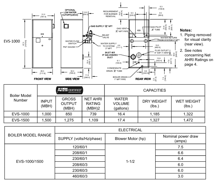
Covering 8 models (EVS-500 to EVS-3000), the core parameter differences are as follows (taking typical models as an example):
Model Input Power (MBH) Total Output (MBH) Net AHRI Rated (MBH) Water Capacity (gallon) Dry Weight (pound) Wet Weight (pound) Power Supply/Fan Power
EVS-500 500 431 375 6.1 722 823 120V/189 horsepower
EVS-1000 1000 850 739 16.4 1185 1322 120V/1.5 horsepower
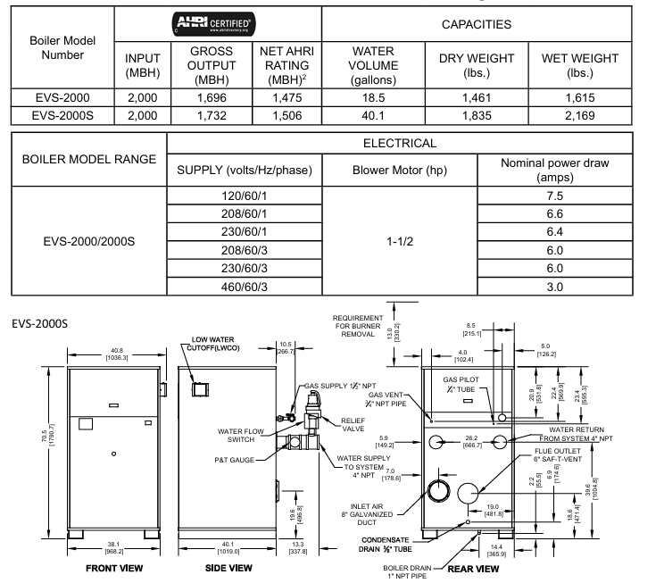
EVS-2000S 2000 1732 1506 40.1 1835 2169 120V/1.5 horsepower
EVS-3000 3000 2610 2270 43.1 2193 2552 208V/2 horsepower
General restrictions: Maximum working pressure of 160 PSI, medium temperature -40~+90 ° C, ambient temperature -40~+85 ° C, condensate pH value 3-5 (requires neutralization treatment).
Installation specifications (key requirements)
1. Pre requirements
Installation qualification: It is required to be operated by a certified Plumber/Gas Fitter (mandatory in Massachusetts). Before installation, local regulations must be confirmed to ensure a safe distance from combustible materials (6 inches left/right/back, 24 inches front, 18 inches for flue connections, and 24-36 inches for maintenance spacing depending on the model).
Space and ventilation: Determine whether a "non confined space" (≥ 50 ft ³/1000 Btu/h) or a "confined space" based on the space volume and total gas input. A confined space requires two permanent ventilation openings (within 12 inches at the top and 12 inches at the bottom, with a minimum diameter of 3 inches); Sealed combustion engine models can be exempted from indoor ventilation, but the intake pipe needs to be installed according to regulations.
2. Core system installation
(1) Ventilation system
Type: Supports positive pressure ventilation (side wall/vertical, maximum equivalent length of 50 feet, non confluent) and negative pressure ventilation (traditional chimney, requiring a vertical height of 15 feet or more and double acting air pressure dampers), ventilation ducts require AL29-4C ® Wait for condensation resistant materials, tilt the horizontal section at least 1 inch every 4 feet, and keep the terminal away from doors and windows (below 4 feet/horizontal 4 feet/above 1 foot) and gas meters (4 feet).
Special requirements: Massachusetts sidewall ventilation requires the installation of carbon monoxide detectors with backup batteries (1 per floor) and 8-foot high signage ("GAS VENT DirectLY BELOW. KEEP CLEAR").
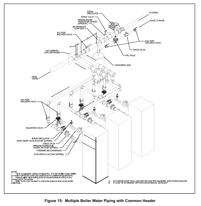
(2) Water system
Water quality requirements: hardness ≤ 8.5 grains (150 ppm), pH 8.8-9.2, requiring professional water treatment (anti oxidation, scaling), ethylene glycol usage not exceeding 50%, and rust inhibitor needs to be added; The new pipe needs to be cleaned with trisodium phosphate (TSP), and the old system needs to be equipped with a filter at the return water end.
Pipeline specifications: The supply/return water diameter should be 2-4 inches (depending on the model), and the flow rate should comply with Table 2 (such as EVS-500 minimum 22 gpm, maximum 43 gpm). The return water temperature should not be lower than 130 ° F (anti condensation), and the temperature difference should not exceed 40 ° F (anti heat exchanger damage); Safety valves (not shut-off valves), exhaust devices, and expansion tanks need to be installed.
(3) Gas system
Pressure requirements: The minimum inlet pressure for natural gas is 4-9 inches of water column (depending on the model), for propane it is 8 inches of water column, and for maximum pressure it is 14 inches of water column. For overpressure, an additional pressure regulator must be installed (no multiple boilers can share one); Gas pipes need to undergo leak testing (using soapy water, no open flames), and install sediment traps and manual shut-off valves.
Pipe diameter selection: Refer to Table 4 (such as the equivalent length of 10 feet for a 1-inch SCH40 pipe with a capacity of 514 ft ³/h), and consider the equivalent length of the pipe fittings (Table 6, such as the equivalent length of 1.55-20.2 feet for a 90 ° elbow).
(4) Electrical system
Power supply: requires independent circuit and fuse switch, voltage 120/208/230/460V (depending on model), grounding in accordance with NFPA 70; Do not connect the boiler and circulating pump to the same fuse switch. Isolation relays are required for low voltage control (24V), and short circuiting of safety controls is prohibited.
Operation and debugging process
1. Check before startup
Confirm that the installation of ventilation, water, gas, and electrical systems is compliant, turn off all power sources and gas valves, empty the air in the gas pipeline (wait for 5 minutes), check for no gas leaks, and then open the gas valve.
2. System startup steps
Water injection and exhaust: Close the boiler water supply valve, exhaust in zones (drain to no bubbles for 30 seconds in each zone), fill the system to working pressure, and check for water leakage.
Power on and debugging: Turn on the power, confirm the direction and flow switch function of the circulation pump, and set TSBC ™ Controller (see Chapter 9), check the fan direction (test during pre blowing).
Flame debugging: Verify the ignition flame (blue stable, signal 1.5-5.0 VDC) and the main flame (uniform orange), adjust the air-fuel ratio (high flame O ₂ 4-6%, low flame O ₂ 5.5-7%) to ensure CO ≤ 400 ppm.
3. Conventional operations
Ignition command: via TSBC ™ Activate the controller or external thermostat, manual ignition is prohibited; When you smell gas, turn off all electrical appliances, stay away from the building, and contact the gas supplier/fire department.
Operation monitoring: Real time monitoring of outlet temperature, modulation rate, flame signal to ensure that safety controls such as safety valves, high limit temperature controllers (manually reset), and low water level cut-off devices are functioning properly.
Maintenance and troubleshooting
1. Maintenance cycle and content
Operational requirements for periodic maintenance projects
Daily inspection around the boiler, instrument readings, and flame observation to ensure that there are no flammable materials and no abnormal flames
Weekly igniter, flame signal, gas valve leakage testing, fuel valve closure testing, safety shutdown time
Monthly flue/condensate drainage, gas pressure interlock testing to clean condensate water and ensure pressure is within normal range
Half year instrument calibration, air filter replacement, circulation pump maintenance, filter cleaning with soapy water, pump maintenance according to manufacturer's specifications
Annual heat exchanger inspection, air-fuel ratio re inspection, safety valve testing, disassembly panel inspection for corrosion, and safety valve testing in accordance with ASME specifications
2. Common fault handling
Possible causes and solutions for alarm information
Low Water Level: The low water level cut-off device triggers a manual reset to check the water replenishment system
Low Water Flow circulation pump malfunction or pipeline blockage, confirm pump operation, clean filter
Fuel Limit gas pressure too high/too low reset pressure switch, check regulator/gas pipeline
High Temp Limit: If the water temperature exceeds the safe value, manually reset the high temperature controller and check the load/circulation system
FSG Fault Flame Protection Device Fault Reset Device, Check Igniter/UV Sensor
3. Spare parts and maintenance
Spare parts ordering: obtained through Thermal Solutions distributors (Lancaster warehouse), providing model and serial numbers; Key spare parts such as heat exchanger (EVS-500:103530-01), fan (EVS-750:81156018), and gas valve (V4295A series) require original factory parts.
Maintenance taboos: Do not disassemble the burner (easily damaged). Before electrical maintenance, all power sources must be cut off and locked. Replacement of controls must be consistent with the original factory model.
TSBC ™ Thermal Solutions Boiler Control
1. Core functions
Support boiler modulation control, multi boiler master-slave linkage (up to 8 units, RJ11 networking), outdoor temperature reset (adjust water temperature according to outdoor temperature, energy-saving), domestic hot water priority (DHWP), fault diagnosis (store 10 alarm records).
2. Key settings
Basic parameters: Warm Season Shutdown (WWSD) set point at 70 ° F, master-slave start triggering 90% modulation rate, stop triggering 25%, rotation period of 168 hours (balanced wear); The default PID parameters are local P=20, I=30, and remote P=20, I=30 (adjustable as needed).
Operation modes: manual mode (setting modulation rate from 0-100%), automatic mode (controlled by outlet/remote temperature), automatic switching to standby mode in case of sensor failure (such as remote sensor failure → outlet sensor control).
- YOKOGAWA
- Reliance
- ADVANCED
- SEW
- ProSoft
- WATLOW
- Kongsberg
- FANUC
- VSD
- DCS
- PLC
- man-machine
- Covid-19
- Energy and Gender
- Energy Access
- Renewable Integration
- Energy Subsidies
- Energy and Water
- Net zero emission
- Energy Security
- Critical Minerals
- A-B
- petroleum
- Mine scale
- Sewage treatment
- cement
- architecture
- Industrial information
- New energy
- Automobile market
- electricity
- Construction site
- HIMA
- ABB
- Rockwell
- Schneider Modicon
- Siemens
- xYCOM
- Yaskawa
- Woodward
- BOSCH Rexroth
- MOOG
- General Electric
- American NI
- Rolls-Royce
- CTI
- Honeywell
- EMERSON
- MAN
- GE
- TRICONEX
- Control Wave
- ALSTOM
- AMAT
- STUDER
- KONGSBERG
- MOTOROLA
- DANAHER MOTION
- Bentley
- Galil
- EATON
- MOLEX
- Triconex
- DEIF
- B&W
- ZYGO
- Aerotech
- DANFOSS
- KOLLMORGEN
- Beijer
- Endress+Hauser
- schneider
- Foxboro
- KB
- REXROTH
- YAMAHA
- Johnson
- Westinghouse
- WAGO
- TOSHIBA
- TEKTRONIX
- BENDER
- BMCM
- SMC
- HITACHI
- HIRSCHMANN
- XP POWER
- Baldor
- Meggitt
- SHINKAWA
- Other Brands
- UniOP
- KUKA
- IBA
- Beckhoff
- ADLINK
-
ADLINK HPCI-14S12U - Industrial Control Backplane 12PCI Backplane PCI-14S Passive Backplane
-
ADLINK PCIe-GIE74C - image acquisition card 4-CH GigE Vision PoE+ Frame Grabber
-
ADLINK PCI-8164 - control card 4-Axis Advanced Motion Controller Board
-
ADLINK PCIe-U304 - 4 Port USB3 PCIe Frame Grabbers USB Screw Hole Card
-
ADLINK PCI-9112 - Multi-Function Data Acquisition Card DAQ Card
-
ADLINK PCI-7432 - 51-12013-0A50 4-CH Isolated Numérique I/O PCI Cartes Digital I/O Card
-
ADLINK PCA-6106P3-0C1 REV.C1 - backplane 6-Slot Passive Backplane Board
-
ADLINK PCI-7224 - 24-CH Opto-Isolated Digital I/O PCI Board
-
ADLINK CPCI-7433R(G) - Digital Input Board Rear I/O CompactPCI Card
-
ADLINK EBP-13E4 - 51-46703-0A30 Industrial PC Backplane Passive Backplane
-
ADLINK PCIE-HDV62 - Image acquisition card High Definition Video Frame Grabber
-
ADLINK EBP-13E4 - 51-46703-0A30 Industrial Backplane Board Passive Backplane
-
ADLINK 90111-B1 / CPCI-6770 - PCB CPU MODULE CompactPCI Single Board Computer
-
ADLINK PCI-7248 - DATA ACQUISITION PCI CARD 48-CH Parallel Digital I/O Board
-
ADLINK PCI-7230 - 51-12003-0a50 board PCI7230 32-CH Isolated Digital I/O Card
-
ADLINK PCI2A000CB - 51-20000-0B30 Multi-Function DAQ Card Baseboard
-
ADLINK PCI-8134-005 - 4-Axis Motion Controller Card
-
ADLINK PCI-7224 - 24-CH Opto-Isolated Digital I/O PCI Card
-
ADLINK PCI-7434 - 64-CH Isolated Digital Output Card
-
ADLINK PCI-8132 - motion control card 2-Axis Servo & Stepper Controller
-
ADLINK PCI-8134 - Motion Controller PCI Card 4-Axis Controller Board
-
ADLINK PCI-8164 - Motion Control Card 51-12406-0A40 4-Axis Controller
-
ADLINK 51-12001-0C20 - Circuit Board Data Acquisition Interface Module Hardware
-
ADLINK NuPR0-840 - industrial control motherboard Full-Size PICMG CPU Board
-
ADLINK PCI-7444 - 51-12023-0A10 card 128-CH Isolated Digital Output Board
-
ADLINK PCI-1612B - data acquisition card 4-Port RS-232/422/485 Serial Communication Card
-
ADLINK PCI-6208V 009 - 8/16-CH 16-Bit Analog Output Cards PCB-I-E-482=6BX3
-
ADLINK NUPRO-935A/LV - industrial control motherboard Full-Size PICMG SBC Board
-
ADLINK PCI-9114DG - Multi-Function DAQ Card Data Acquisition PCI Card
-
ADLINK ACL-7130 - Data acquisition card Isolated Digital I/O Board
-
ADLINK ABX-6300D-4E1-BP - board ABX6300D4E1BP Video Interface Expansion Card
-
ADLINK CPCI-6940 - CPCI-6940/D1539/M16-0(EA)-000E 6U CompactPCI Processor Board
-
ADLINK NuPRO-760 - industrial control motherboard Half-Size PICMG SBC CPU Board
-
ADLINK IMB-M42H (G)-0020 - industrial control motherboard LGA1155 Micro-ATX Mainboard
-
ADLINK RTV-24 / PCI-MP4S - 51-12519-1C30 4-Channel Real Time Video Capture Board
-
ADLINK PCI-8134 - 4-Axis Servo & Stepper Motion Controller Card
-
ADLINK MXC-6101D - V.PC000.002.ST.00 Box PC Configurable Embedded Computer
-
ADLINK PCI-8134A - 51-12421-0A10 Motion Control Card 4-Axis Controller Card
-
ADLINK DIN-100S / DIN-100SA1 - Technology SCSI-II TB 100-PIN Terminal Block Board
-
ADLINK DIN-812M001 / DIN812M001 - 51-14034-0A1 51140340A1 Terminal Module Breakout Interface
-
ADLINK PCI-8164 - Servo motion control 4-Axis Advanced Controller Card
-
ADLINK PCIe-GIE64 - Acquisition card GigE Vision PoE+ Frame Grabber
-
ADLINK M-302 - Industrial control motherboard ATX PC Board Mainboard
-
ADLINK PCI-8134 - Motion Controller PCI Card 4-Axis Controller Board
-
ADLINK PCI-RTV24 - Image capture card Analog Video Frame Grabber
-
ADLINK PCI-8102 - Motion control card 2-Axis Servo & Stepper Controller Board
-
ADLINK PCI-9112 REV.B1 - Card Multi-Function Data Acquisition Card
-
ADLINK HSI-DI32-M-N / HSL-TB32-M-DIN - Discrete I/O MODULE Distributed Automation Module System
-
ADLINK PCI-7296 - IO card REV.A3 96-CH Parallel Digital I/O Card
-
ADLINK DIN-814P-A4 / 814Y - terminal board Motion Control Interface Block
-
ADLINK DIN-814P-A4 - 51-14056-0A10 PCB-I-E-2736=ZA01 Screw Terminal Board Breakout
-
ADLINK M-322 - motherboard Industrial Control Computer Mainboard
-
ADLINK NUPRO-406 REV:B1 - industrial control motherboard Full-Size PICMG CPU Board
-
ADLINK AMP-204C - card DSP-Based 4-Axis Advanced Pulse-Train Controller
-
ADLINK HPCI14S REV.B1 - industrial computer baseboard 14-Slot Passive Backplane
-
ADLINK PCI-7250 - 8-CH Relay Output & 8-CH Isolated DI PCI Card
-
ADLINK EBP-13E2 - baseplate Passive Backplane Industrial Computer Chassis Board
-
ADLINK LPCI-3488A - PCI-GPIB card 51-12801-0A30 acquisition card IEEE-488 Interface Board
-
ADLINK PCI-6216V-GL - 51-12201-0C30 16-CH 16-Bit Voltage Analog Output Card
-
ADLINK ACL-8454 - 16-CH Isolated Digital I/O & 4-CH Counter Card
-
ADLINK HPCI-9S7U - backplane Passive Backplane Compatible with NuPRO-A301 852 841 842
-
ADLINK DAQ-2010-007 - Simultaneous-Sampling Multi-Function Data Acquisition Card
-
ADLINK MP-C154 - 51-64205-0A10 Motion Control Card 4-Axis Controller Board
-
ADLINK MXE-202/mSSD16B/WiFi-BT - Matrix Rugged I/O Platform Embedded Fanless Computer
-
ADLINK CM-920-R-17 - PC/104-Plus Single Board Computer Module Intel Celeron M
-
ADLINK PCI-7250 NSMP - 8-CH Relay Output & 8-CH Isolated DI Card
-
ADLINK PCI-8164 - 4-Axis Motion Controller PCI Card W/ Cable and Breakout Box
-
ADLINK EMX-100 - Ethernet-based 4-axis Motion Controllers Distributed Motion Module
-
ADLINK PCI-8134A - Press control card 4-Axis Motion Controller Board
-
ADLINK M-845EG REV:3.2 - industrial motherboard Pentium 4 Socket 478 Micro-ATX
-
ADLINK PCI-9114A Rev A2 DG - card High-Resolution Multi-Function Data Acquisition Board
-
ADLINK IEC-915GV - REV 1.1 Industrial motherboard Socket 478 CPU Board
-
ADLINK PCI-9111DG(G) - Data Acquisition Card Multi-Function DAQ Card
-
ADLINK HPCI-15S10 REV:B2 - Industrial computer base plate Passive Backplane Board
-
ADLINK NuPR0-840 / NuPR0-840DV - industrial control motherboard Full-size PICMG CPU Board
-
ADLINK RTV-24 / PCI-MP4S - 51-12519-1C30 4-Channel Real Time Video Capture Board
-
ADLINK NUPRO-780 - industrial control motherboard Pentium III Single Board Computer
-
ADLINK PCI-7296 - 0050 card 96-CH Opto-Isolated Parallel DIO Card Set
-
ADLINK NUPRO-780 - industrial control motherboard PICMG Full-Size SBC
-
ADLINK PCI-7248 - 51-12006-0A3 002 Pci 7248 48-CH Parallel Digital I/O Card
-
ADLINK cPCI-6626 - 6U CompactPCI 2.0 Blades i7-2710QE PCB-I-E-2570=9N41
-
ADLINK MXC-6322D(G) - Industrial Fanless Computer
-
ADLINK cPCI-8168-004 - CompactPci NulPC Motion Control Board 51-36402-0A3
-
ADLINK CPCI-7300[G] - COMPACTPCI Digital I/O Card Data Acquisition
-
ADLINK CPCI-6626/2710/M4G - COMPACTPCI COMPUTER BOARD
-
ADLINK cPCI-8168-009 - cPCI NulPC Motion Control Board
-
ADLINK cPCI-6626/2710/M4G - VME CPU Board Computer Board
-
ADLINK CPCI-R6200(G)-0040 - COMPACTPCI CONTROL BOARD
-
ADLINK CPCI-3840/PM18/M1G(G)-3650 - COMPACTPCI CPU Module Single Board Computer
-
ADLINK cPCI-7248 - 48-CH Opto-22 Compatible Digital I/O Module
-
ADLINK DLAP-211-JNX - NVIDIA Jetson Xavier NX Edge AI Inference Platform
-
ADLINK cPCI-3544 - Series 4-Port RS-422/485 Isolated Serial Communications Card
-
ADLINK CM1-86DX3 - PC/104 SBC Stanley Vortex86DX3 CPU 2GB Ram
-
ADLINK DLAP-211-JNX - NVIDIA Jetson Xavier NX Edge AI Inference Platform
-
ADLINK cPCI-3544 - Series 4-Port RS-422/485 Isolated Serial Communications Card
-
ADLINK CM1-86DX3 - PC/104 SBC Stanley Vortex86DX3 CPU 2GB Ram
-
ADLINK PCI-7433 - switch value acquisition card Isolated Digital Input Card
-
ADLINK PCI-9112 - 51-12252-0D20 Multi-Function Data Acquisition Card
-
ADLINK NUPRO-A301 REV:1.4 - industrial control motherboard PICMG Full-Size SBC
-
ADLINK 51-18502-0A10 - Frame Grabber Image Acquisition Interface Card
-
ADLINK PCI-7296 - 51-12009-0A50 PCB-I-E-925=6DX1 96-CH Parallel Digital I/O Board
-
ADLINK PCI-8132 GP A2 - Motion Control Card 2-Axis Servo & Stepper Controller
-
ADLINK PCI-7442 - switch quantity card data acquisition card 64-CH Isolated Card
-
ADLINK HPX-13S4 - baseboard PICMG 1.3 Passive Backplane Chassis Baseplate
-
ADLINK NuPRO-590 / NTC-567-ZM-F36 - Single Board Computer PCB-I-E-1853=9L21 Half-Size SBC
-
ADLINK PCIe-8332 - 16-axis plate Motion Control Hardware Card
-
ADLINK NuPRO-775 REV.B1 - motherboard Pentium 4 Full-Size PICMG SBC
-
ADLINK PXI-3920 - Embedded Controller 3U PXI cPCI System Intelligence Board
-
ADLINK PCI-8134 - driver card motion control card 4-Axis Controller Board
-
ADLINK HSL-DI32-M-N-011 / HSL-TB32-M-DIN - Digital Input & Base Module PLC Distributed I/O System
-
ADLINK PCI-6216V-206 / PCI-208V 009 - 16 CH 16bit analog output card
-
ADLINK NuPro-E330 - 51-41805-0A20 PCB Single Board Computer Host Board
-
ADLINK PCI-1622C - Card 8-Port RS-232/422/485 PCI Serial Communication Board
-
ADLINK PCIe-7432 - 51-18402-0A10 Carte PCIe Avec Plage D'Entrée Élevée Isolated DIO Card
-
ADLINK PCI-7250 - PCI Acquisition Card 8-CH Relay Output Isolated DI Card
-
ADLINK PCI-7230 - 32-CH Isolated Digital I/O Card
-
ADLINK PCI-8164 - PCB 4-Axis Motion Controller Card
-
ADLINK PCI-7854 - Collection card High-Speed Link Distributed Motion Controller
-
ADLINK NuPRO-935A/LV - industrial control computer motherboard Full-Size PICMG SBC
-
ADLINK IMB-M40H - motherboard IH61-AA4 1155 LGA1155 Micro-ATX Mainboard
-
ADLINK PCI-7248 - Linhua 51-12006-0A40 48-CH Parallel Digital I/O Card
-
ADLINK HPCI-14S12U - Linhua industrial computer baseboard Passive Backplane
-
ADLINK PCI-8132 Rev.A2 - 2-Axis Servo & Stepper Motion Controller Card
-
ADLINK ACL-8111 - ISA card Multi-Function DAQ Card
-
ADLINK ACL-8111 - ISA card Multi-Function Data Acquisition Board
-
ADLINK PCI-7200 REV.A3 - Digital I/O card 12MB/s High-Speed Parallel Digital I/O
-
ADLINK PCI-7296 REV.A3 - 96-CH High-Density Opto-Isolated DIO Card
-
ADLINK PCI-7434 - 64-CH Isolated Digital Output Card

K-JIANG

Add: Jimei North Road, Jimei District, Xiamen, Fujian, China
Tell:+86-15305925923