
K-WANG
+086-15305925923
Service expert in industrial control field!


Product
Article
NameDescriptionContent
Adequate Inventory, Timely Service
pursuit of excellence


Ship control system
Equipment control system
Power monitoring system
Current position:
新闻动态
newS
Brand
HIMatrix F30 01 Safety-Related Controller
The safety-related F30 controller is a compact system in a metal housing with 20 digital inputs and 8 digital outputs.
The controller is available in various model variants for SILworX and ELOP II Factory.
The device is suitable for mounting in Ex-zone 2.
The device is TÜV-certified for safety-related applications up to SIL 3 (IEC 61508, IEC 61511 and IEC 62061), Cat. 4 and PL e (EN ISO 13849-1) and SIL 4 (EN 50126, EN 50128 and EN 50129).
Further safety standards, application standards and test standards are specified in the certificates available on the HIMA website.
HIMatrix F30 01 Safety-Related Controller
Product Description
The safety-related F30 controller is a compact system in a metal housing with 20 digital inputs and 8 digital outputs.
The controller is available in various model variants for SILworX and ELOP II Factory.
The device is suitable for mounting in Ex-zone 2.
The device is TÜV-certified for safety-related applications up to SIL 3 (IEC 61508, IEC 61511 and IEC 62061), Cat. 4 and PL e (EN ISO 13849-1) and SIL 4 (EN 50126, EN 50128 and EN 50129).
Further safety standards, application standards and test standards are specified in the certificates available on the HIMA website.
Safety Function
The controller is equipped with safety-related digital inputs and outputs.
Safety-Related Digital Inputs
The controller is equipped with 20 digital inputs. The state (HIGH, LOW) of each input is signaled by an individual LED.
Mechanical contacts without own power supply or signal power source can be connected to the inputs.
Potential-free mechanical contacts without own power supply are fed via an internal short circuit-proof 24 V power source (LS+). Each of them supply a group of 4 mechanical contacts.
With signal voltage sources, the corresponding ground must be connected to the input (L-)
For the external wiring and the connection of sensors, apply the de-energized-to-trip principle.
Thus, if a fault occurs, the input signals adopt a de-energized, safe state (low level).
If an external wire is not monitored, an open-circuit is considered as safe low level.
Reaction in the Event of a Fault
If the device detects a fault on a digital input, the user program processes a low level in accordance with the de-energized to trip principle.
The device activates the FAULT LED.
In addition to the channel signal value, the user program must also consider the corresponding error code.
The error code allows the user to configure additional fault reactions in the user program.
Line Control
Line control is used to detect short-circuits or open-circuits and can be configured for the F30 system, e.g., on EMERGENCY STOP inputs complying with Cat. 4 and PL e in accordance with EN ISO 13849-1.
To this end, connect the digital outputs DO 1 through DO 8 of the system to the digital inputs DI of the same system as follows:
The controller pulses the digital outputs to detect short-circuits and open-circuits on the lines connected to the digital inputs.
To do so, configure the Value [BOOL] -> system variable in SILworX or the DO[0x].Value system signal in ELOP II Factory.
The variables for the pulsed outputs must begin with channel 1 and reside in direct sequence, one after the other.
If the following faults occur, the FAULT LED located on the front plate of the controller blinks,the inputs are set to low level and an (evaluable) error code is created:
Cross-circuit between two parallel wires.
Invalid connections of two lines (e.g., DO 2 to DI 3),
Earth fault on one wire (with earthed ground only).
Open-circuit or open contacts, i.e., including when one of the two EMERGENCY STOP
switches mentioned above has been engaged, the FAULT LED blinks and the error code is created.
Equipment, Scope of Delivery
The following table specifies the available controller variants:
F30 01:Controller (20 digital inputs, 8 digital outputs), Operating temperature: 0...+60 °C, for ELOP II Factory programming tool.
F30 011 (-20 °C) :Controller (20 digital inputs, 8 digital outputs), Operating temperature: -20...+60 °C, for ELOP II Factory programming tool
F30 014:Controller (20 digital inputs, 8 digital outputs), Operating temperature: -25...+70 °C (temperature class T1), Vibration and shock tested according to EN 50125-3 and EN 50155,
class 1B according to IEC 61373, for ELOP II Factory programming tool
F30 01 SILworX:Controller (20 digital inputs, 8 digital outputs), Operating temperature: 0...+60 °C, for SILworX programming tool
F30 011 SILworX (-20 °C):Controller (20 digital inputs, 8 digital outputs), Operating temperature: -20...+60 °C, for SILworX programming tool
F30 014 SILworX:Controller (20 digital inputs, 8 digital outputs), Operating temperature: -25...+70 °C (temperature class T1), Vibration and shock tested according to EN 50125-3 and EN 50155, class 1B according to IEC 61373, for SILworX programming tool
Type Label
The type plate contains the following details:
Product name
Bar code (1D or 2D code)
Part no.
Production year
Hardware revision index (HW Rev.)
Firmware revision index (FW Rev.)
Operating voltage
Mark of conformity
Mounting the F30 in Zone 2
(EC Directive 94/9/EC, ATEX)
The controller is suitable for mounting in zone 2. Refer to the corresponding declaration of conformity available on the HIMA website.
When mounting the device, observe the special conditions specified in the following section.
Specific Conditions X
1. Mount the HIMatrix F30 controller in an enclosure that meets the EN 60079-15 requirements and achieves a type of protection of at least IP54, in accordance with EN 60529. Provide the enclosure with the following label:
Work is only permitted in the de-energized state Exception:
If a potentially explosive atmosphere has been precluded, work can also performed when the controller is under voltage.
2. The enclosure in use must be able to safely dissipate the generated heat. Depending on the output load and supply voltage, the HIMatrix F30 has a power dissipation ranging between 12 W and 33 W.
3. Protect the HIMatrix F30 with a 10 A time-lag fuse.
The 24 VDC power must come from a power supply unit with safe isolation. Use power supply units of type PELV or SELV only.
4. Applicable standards:
VDE 0170/0171 Part 16, DIN EN 60079-15: 2004-5
VDE 0165 Part 1, DIN EN 60079-14: 1998-08
Configuration with SILworX
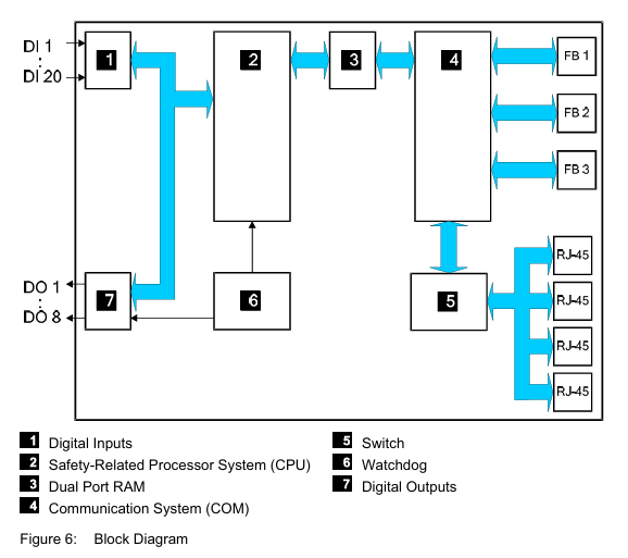
In the Hardware Editor, the controller is represented like a base plate equipped with the following modules:
Processor module (CPU)
Communication module (COM)
Input module (DI 20)
Output module (DO 8)
Double-click the module to open the Detail View with the corresponding tabs. The tabs are used to assign the global variables configured in the user program to the system variables.
Parameters and Error Codes for the Inputs and Outputs
The following tables specify the system parameters that can be read and set for the inputs and outputs, including the corresponding error codes.
In the user program, the error codes can be read using the variables assigned within the logic.
The error codes can also be displayed in SILworX.
Configuration with ELOP II Factory
Configuring the Inputs and Outputs
The signals previously defined in the Signal Editor (Hardware Management) are assigned to the individual channels (inputs and outputs) using ELOP II Factory. Refer to the system manual for compact systems or the online help for more details.
The following chapter describes the system signals used for assigning signals in the controller.
Signals and Error Codes for the Inputs and Outputs
The following tables specify the system signals that can be read and set for the inputs and outputs, including the corresponding error codes.
In the user program, the error codes can be read using the signals assigned within the logic.
The error codes can also be displayed in ELOP II Factory.
Operation
The controller F30 is ready for operation. No specific monitoring is required for the controller.
Handling
Handling of the controller during operation is not required.
Diagnosis
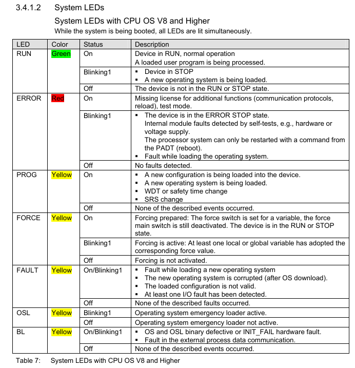
A first diagnosis results from evaluating the LEDs, see Chapter 3.4.1.
The device diagnostic history can also be read using the programming tool.
Maintenance
No maintenance measures are required during normal operation.
If a failure occurs, the defective module or device must be replaced with a module or device of the same type or with a replacement model approved by HIMA.
Only the manufacturer is authorized to repair the device/module.
Faults
If the test harnesses detect safety-critical faults, the module enters the STOP_INVALID state and will remain in this state. This means that the input signals are no longer processed by the device and the outputs switch to the de-energized, safe state. The evaluation of diagnostics provides information on the fault cause.
Maintenance Measures
The following measures are required for the device:
Loading the operating system, if a new version is required
Executing the proof test
Loading the Operating System
HIMA is continuously improving the operating system of the devices.
HIMA recommends to use system downtimes to load a current version of the operating system into the devices.
Refer to the release list to check the consequences of the new operation system version on the system!
The operating system is loaded using the programming tool.
Prior to loading the operating system, the device must be in STOP (displayed in the programming tool). Otherwise, stop the device.
For more information, refer to the programming tool documentation.
Proof Test
HIMatrix devices and modules must be subjected to a proof test in intervals of 10 years.
Decommissioning
Remove the supply voltage to decommission the device. Afterwards pull out the pluggable screw terminal connector blocks for inputs and outputs and the Ethernet cables.
Transport
To avoid mechanical damage, HIMatrix components must be transported in packaging.
Always store HIMatrix components in their original product packaging. This packaging also provides protection against electrostatic discharge. Note that the product packaging alone is not suitable for transport.
Disposal
Industrial customers are responsible for correctly disposing of decommissioned HIMatrix hardware. Upon request, a disposal agreement can be arranged with HIMA.
All materials must be disposed of in an ecologically sound manner.

- YOKOGAWA
- Reliance
- ADVANCED
- SEW
- ProSoft
- WATLOW
- Kongsberg
- FANUC
- VSD
- DCS
- PLC
- man-machine
- Covid-19
- Energy and Gender
- Energy Access
- Renewable Integration
- Energy Subsidies
- Energy and Water
- Net zero emission
- Energy Security
- Critical Minerals
- A-B
- petroleum
- Mine scale
- Sewage treatment
- cement
- architecture
- Industrial information
- New energy
- Automobile market
- electricity
- Construction site
- HIMA
- ABB
- Rockwell
- Schneider Modicon
- Siemens
- xYCOM
- Yaskawa
- Woodward
- BOSCH Rexroth
- MOOG
- General Electric
- American NI
- Rolls-Royce
- CTI
- Honeywell
- EMERSON
- MAN
- GE
- TRICONEX
- Control Wave
- ALSTOM
- AMAT
- STUDER
- KONGSBERG
- MOTOROLA
- DANAHER MOTION
- Bentley
- Galil
- EATON
- MOLEX
- Triconex
- DEIF
- B&W
- ZYGO
- Aerotech
- DANFOSS
- KOLLMORGEN
- Beijer
- Endress+Hauser
- schneider
- Foxboro
- KB
- REXROTH
- YAMAHA
- Johnson
- Westinghouse
- WAGO
- TOSHIBA
- TEKTRONIX
- BENDER
- BMCM
- SMC
- HITACHI
- HIRSCHMANN
- XP POWER
- Baldor
- Meggitt
- SHINKAWA
- Other Brands
- UniOP
- KUKA
- IBA
- Beckhoff
- ADLINK
52
-
ADLINK HPCI-14S12U - Industrial Control Backplane 12PCI Backplane PCI-14S Passive Backplane
-
ADLINK PCIe-GIE74C - image acquisition card 4-CH GigE Vision PoE+ Frame Grabber
-
ADLINK PCI-8164 - control card 4-Axis Advanced Motion Controller Board
-
ADLINK PCIe-U304 - 4 Port USB3 PCIe Frame Grabbers USB Screw Hole Card
-
ADLINK PCI-9112 - Multi-Function Data Acquisition Card DAQ Card
-
ADLINK PCI-7432 - 51-12013-0A50 4-CH Isolated Numérique I/O PCI Cartes Digital I/O Card
-
ADLINK PCA-6106P3-0C1 REV.C1 - backplane 6-Slot Passive Backplane Board
-
ADLINK PCI-7224 - 24-CH Opto-Isolated Digital I/O PCI Board
-
ADLINK CPCI-7433R(G) - Digital Input Board Rear I/O CompactPCI Card
-
ADLINK EBP-13E4 - 51-46703-0A30 Industrial PC Backplane Passive Backplane
-
ADLINK PCIE-HDV62 - Image acquisition card High Definition Video Frame Grabber
-
ADLINK EBP-13E4 - 51-46703-0A30 Industrial Backplane Board Passive Backplane
-
ADLINK 90111-B1 / CPCI-6770 - PCB CPU MODULE CompactPCI Single Board Computer
-
ADLINK PCI-7248 - DATA ACQUISITION PCI CARD 48-CH Parallel Digital I/O Board
-
ADLINK PCI-7230 - 51-12003-0a50 board PCI7230 32-CH Isolated Digital I/O Card
-
ADLINK PCI2A000CB - 51-20000-0B30 Multi-Function DAQ Card Baseboard
-
ADLINK PCI-8134-005 - 4-Axis Motion Controller Card
-
ADLINK PCI-7224 - 24-CH Opto-Isolated Digital I/O PCI Card
-
ADLINK PCI-7434 - 64-CH Isolated Digital Output Card
-
ADLINK PCI-8132 - motion control card 2-Axis Servo & Stepper Controller
-
ADLINK PCI-8134 - Motion Controller PCI Card 4-Axis Controller Board
-
ADLINK PCI-8164 - Motion Control Card 51-12406-0A40 4-Axis Controller
-
ADLINK 51-12001-0C20 - Circuit Board Data Acquisition Interface Module Hardware
-
ADLINK NuPR0-840 - industrial control motherboard Full-Size PICMG CPU Board
-
ADLINK PCI-7444 - 51-12023-0A10 card 128-CH Isolated Digital Output Board
-
ADLINK PCI-1612B - data acquisition card 4-Port RS-232/422/485 Serial Communication Card
-
ADLINK PCI-6208V 009 - 8/16-CH 16-Bit Analog Output Cards PCB-I-E-482=6BX3
-
ADLINK NUPRO-935A/LV - industrial control motherboard Full-Size PICMG SBC Board
-
ADLINK PCI-9114DG - Multi-Function DAQ Card Data Acquisition PCI Card
-
ADLINK ACL-7130 - Data acquisition card Isolated Digital I/O Board
-
ADLINK ABX-6300D-4E1-BP - board ABX6300D4E1BP Video Interface Expansion Card
-
ADLINK CPCI-6940 - CPCI-6940/D1539/M16-0(EA)-000E 6U CompactPCI Processor Board
-
ADLINK NuPRO-760 - industrial control motherboard Half-Size PICMG SBC CPU Board
-
ADLINK IMB-M42H (G)-0020 - industrial control motherboard LGA1155 Micro-ATX Mainboard
-
ADLINK RTV-24 / PCI-MP4S - 51-12519-1C30 4-Channel Real Time Video Capture Board
-
ADLINK PCI-8134 - 4-Axis Servo & Stepper Motion Controller Card
-
ADLINK MXC-6101D - V.PC000.002.ST.00 Box PC Configurable Embedded Computer
-
ADLINK PCI-8134A - 51-12421-0A10 Motion Control Card 4-Axis Controller Card
-
ADLINK DIN-100S / DIN-100SA1 - Technology SCSI-II TB 100-PIN Terminal Block Board
-
ADLINK DIN-812M001 / DIN812M001 - 51-14034-0A1 51140340A1 Terminal Module Breakout Interface
-
ADLINK PCI-8164 - Servo motion control 4-Axis Advanced Controller Card
-
ADLINK PCIe-GIE64 - Acquisition card GigE Vision PoE+ Frame Grabber
-
ADLINK M-302 - Industrial control motherboard ATX PC Board Mainboard
-
ADLINK PCI-8134 - Motion Controller PCI Card 4-Axis Controller Board
-
ADLINK PCI-RTV24 - Image capture card Analog Video Frame Grabber
-
ADLINK PCI-8102 - Motion control card 2-Axis Servo & Stepper Controller Board
-
ADLINK PCI-9112 REV.B1 - Card Multi-Function Data Acquisition Card
-
ADLINK HSI-DI32-M-N / HSL-TB32-M-DIN - Discrete I/O MODULE Distributed Automation Module System
-
ADLINK PCI-7296 - IO card REV.A3 96-CH Parallel Digital I/O Card
-
ADLINK DIN-814P-A4 / 814Y - terminal board Motion Control Interface Block
-
ADLINK DIN-814P-A4 - 51-14056-0A10 PCB-I-E-2736=ZA01 Screw Terminal Board Breakout
-
ADLINK M-322 - motherboard Industrial Control Computer Mainboard
-
ADLINK NUPRO-406 REV:B1 - industrial control motherboard Full-Size PICMG CPU Board
-
ADLINK AMP-204C - card DSP-Based 4-Axis Advanced Pulse-Train Controller
-
ADLINK HPCI14S REV.B1 - industrial computer baseboard 14-Slot Passive Backplane
-
ADLINK PCI-7250 - 8-CH Relay Output & 8-CH Isolated DI PCI Card
-
ADLINK EBP-13E2 - baseplate Passive Backplane Industrial Computer Chassis Board
-
ADLINK LPCI-3488A - PCI-GPIB card 51-12801-0A30 acquisition card IEEE-488 Interface Board
-
ADLINK PCI-6216V-GL - 51-12201-0C30 16-CH 16-Bit Voltage Analog Output Card
-
ADLINK ACL-8454 - 16-CH Isolated Digital I/O & 4-CH Counter Card
-
ADLINK HPCI-9S7U - backplane Passive Backplane Compatible with NuPRO-A301 852 841 842
-
ADLINK DAQ-2010-007 - Simultaneous-Sampling Multi-Function Data Acquisition Card
-
ADLINK MP-C154 - 51-64205-0A10 Motion Control Card 4-Axis Controller Board
-
ADLINK MXE-202/mSSD16B/WiFi-BT - Matrix Rugged I/O Platform Embedded Fanless Computer
-
ADLINK CM-920-R-17 - PC/104-Plus Single Board Computer Module Intel Celeron M
-
ADLINK PCI-7250 NSMP - 8-CH Relay Output & 8-CH Isolated DI Card
-
ADLINK PCI-8164 - 4-Axis Motion Controller PCI Card W/ Cable and Breakout Box
-
ADLINK EMX-100 - Ethernet-based 4-axis Motion Controllers Distributed Motion Module
-
ADLINK PCI-8134A - Press control card 4-Axis Motion Controller Board
-
ADLINK M-845EG REV:3.2 - industrial motherboard Pentium 4 Socket 478 Micro-ATX
-
ADLINK PCI-9114A Rev A2 DG - card High-Resolution Multi-Function Data Acquisition Board
-
ADLINK IEC-915GV - REV 1.1 Industrial motherboard Socket 478 CPU Board
-
ADLINK PCI-9111DG(G) - Data Acquisition Card Multi-Function DAQ Card
-
ADLINK HPCI-15S10 REV:B2 - Industrial computer base plate Passive Backplane Board
-
ADLINK NuPR0-840 / NuPR0-840DV - industrial control motherboard Full-size PICMG CPU Board
-
ADLINK RTV-24 / PCI-MP4S - 51-12519-1C30 4-Channel Real Time Video Capture Board
-
ADLINK NUPRO-780 - industrial control motherboard Pentium III Single Board Computer
-
ADLINK PCI-7296 - 0050 card 96-CH Opto-Isolated Parallel DIO Card Set
-
ADLINK NUPRO-780 - industrial control motherboard PICMG Full-Size SBC
-
ADLINK PCI-7248 - 51-12006-0A3 002 Pci 7248 48-CH Parallel Digital I/O Card
-
ADLINK PCI-7230 - 32-CH Isolated Digital I/O Card
-
ADLINK AMP-204C - motion control card 4-Axis Advanced Controller Board
-
ADLINK PCI-1714UL - Card Ultra High-Speed 4-CH Simultaneous Sampling DAQ
-
ADLINK NuPRO-E330 - industrial computer equipment motherboard PICMG 1.3 SHB SBC
-
ADLINK AMP-204C - DSP-Based 4-Axis Advanced Pulse-Train Motion Controller Module
-
ADLINK PCI-7256 - 001 51-12206-0A2 REV.A2 LPCI-7256 16-CH Latching Relay Output Card
-
ADLINK ND6050 - NUDAM DIGITAL I/0 MODULE Distributed I/O Unit
-
ASEM BM100 - Box PC Embedded Fanless Industrial Computer
-
ADLINK PCI-7250 - PCI Acquisition Card 8-CH Relay Output & Isolated DI Board
-
ADLINK PCI-8164 - Servo motion control 4-Axis Controller Card
-
ADLINK NuPRO-A40H - Industrial Motherboard 51-41807-1A30 OSP LGA1155 H61
-
ADLINK ADMAX X300 SERVER - 51066010-0A30 motherboard Multi-Processor Mainboard
-
ADLINK CMe-GIE62+ - 51-32903-0A30 control card PC/104-Plus GigE Vision Frame Grabber
-
ADLINK NUPRO-780 - industrial control motherboard Full-Size PICMG SBC CPU Board
-
ADLINK ETX-AT-N270-18/GKTEL - 51-71111-OB10 motherboard ETX CPU Module Board
-
ADLINK DIN-812M - interface module Terminal Block Connection Board
-
ADLINK IMB-M42H - industrial control motherboard LGA1155 Micro-ATX Mainboard
-
ADLINK PXIS-2508 - 8-slot 3U PXI Instrument Chassis Power Hardware Assembly
-
ADLINK AMP-208C - Motion Control card DSP-Based 8-Axis Pulse-Train Controller
-
ADLINK PCI-9111 / PCI-9111DG - Multi-Function Data Acquisition Card DAQ Board
-
ADLINK IEEE-488 GPIB card - Bus Interface Controller Communication Board
-
ADLINK RTV-24 - 51-12519-1C30 image acquisition card Video Frame Grabber Card
-
ADLINK TB-24P/24-01 - Board 24 Way Screw Terminal Breakout Board
-
ADLINK HSL-DI16DO16-DB-NN - 51-23015-0A40 Distributed Discrete I/O Module Set
-
ADLINK PCI-7442 - switch quantity card data acquisition card 64-CH Isolated Card
-
ADLINK ACL-7130 REV. B2 - industrial control capture card Isolated Digital I/O PCI Card
-
ADLINK PCI-6S / PCI6S - Backplane 6-Slot Passive Backplane Chassis Board
-
ADLINK ACL-8113A - card Isolated Digital Input Card
-
ADLINK CPCI-6208V-003 - board cPCI CompactPCI 8-CH Analog Output Card
-
ADLINK DIN-100S-01(G) - SCSI 100-Pin Terminal Block Interface Board
-
ADLINK PCI-7433 - Isolated Digital Input Card 64-CH
-
ADLINK PCI-9812 - Synchronous sampling analog input card High-Speed DAQ Board
-
ADLINK PCI-7434 REV.B1 - PLOTECH PCB-I-E-1182=6EX2 64-CH Isolated Digital Output Card
-
ADLINK PCIe-RTV24 - 51-18016-0A20 4-CH Real-Time Video Capture Card PCIe Frame Grabber
-
ADLINK PCI-8144 / PCI-8144N - Motion control card 4-Axis Stepper Motor Controller
-
ADLINK DIN-68S-01 - terminal board 68-Pin Connector Terminal Block
-
ADLINK MP-C154 - Motion control card 4-Axis Advanced Controller Card
-
ADLINK PCI-7248 (G) - Motherboard 48-CH Parallel Digital I/O Card
-
ADLINK MXE-1301(G) - Intel Atom D2550+NM10 MXE 1300 Series 93-4130-0030 Embedded Computer
-
ADLINK PRO-841 Rev 2.0 / PRO-060907000670 - CPU 2.26GHz & RAM Industrial PC Board
-
ADLINK NuPRO-E330 - Industrial Motherboard System Host Board PICMG 1.3 SHB
-
ADLINK EBP-13E2 - Passive Backplane Industrial Chassis Baseboard
-
ADLINK PCI-8154 - 4-axis Motion Control Card Servo & Stepper Controller Board
-
ADLINK NuPrO-596 REV.B1 - industrial control motherboard Half-size PICMG CPU Board
-
ADLINK PCI-7852 / PCI-7851 - PLOTECH High-Speed Link Control Card Interface Board
-
ADLINK PCI-9112 - 51-12252-0D20 data acquisition card Multi-Function DAQ
-
ADLINK PCI-9112 - Circuit Board 51-12252-0C20 Multi-Function Data Acquisition Card
-
ADLINK NUPRO-761 REV:1.1 - industrial control motherboard PICMG Full-Size CPU Board

K-JIANG

Add: Jimei North Road, Jimei District, Xiamen, Fujian, China
Tell:+86-15305925923