
K-WANG


Watlow F4T Controller Installation and Failure
Environmental requirements for working temperature: -18~50 ℃ (-0~122 ° F); Storage temperature: -40~85 ℃; Humidity 0~90% RH without condensation
High voltage power supply specifications (F4TXX [1-4]): 85~264Vac 50/60Hz; Low voltage type (F4TXX [5-8]): 20.4~30.8Vac/dc
Power consumption 23W (maximum), 54VA
certification standard UL 61010(File E185611)、CSA 22.2#14(File 158031)、FM Class 3545、CE(EN 61326)、RoHS 2
Watlow F4T Controller Installation and Failure
Product Overview and Basic Information
1. Core parameters and authentication
Protection level: IP65 for front panel, IP10 for empty slot cover
Environmental requirements for working temperature: -18~50 ℃ (-0~122 ° F); Storage temperature: -40~85 ℃; Humidity 0~90% RH without condensation
High voltage power supply specifications (F4TXX [1-4]): 85~264Vac 50/60Hz; Low voltage type (F4TXX [5-8]): 20.4~30.8Vac/dc
Power consumption 23W (maximum), 54VA
certification standard UL 61010(File E185611)、CSA 22.2#14(File 158031)、FM Class 3545、CE(EN 61326)、RoHS 2
2. User interface and operation
Display screen: 4.3-inch TFT PCAP color touch screen, supporting 4 physical buttons (home, menu, return, help)
Core Display: Loop Name, Control Mode (Auto/Manual), Process Value (PV), Set Point (SP), Output Power (PWR)
Menu functions: configuration files (40, 50 steps per file), data logs, system settings (network/security)
Installation and wiring specifications
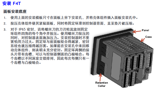
1. Installation method and size
Key requirements for installation type
Panel installation hole size: 117.40mm (width) × 120.14mm (height); The fixing ring should be tightly attached to the panel to ensure an IP65 seal
Embedded installation requires PEM nut posts (such as S0-632-6 Z1 galvanized steel); The bracket is fixed with 6 # 6-32 screws, and the front panel needs to be covered
Install through the wall with a hole of 178 × 122mm; install the heat sink vertically, leaving a ventilation space of ≥ 102mm above and below
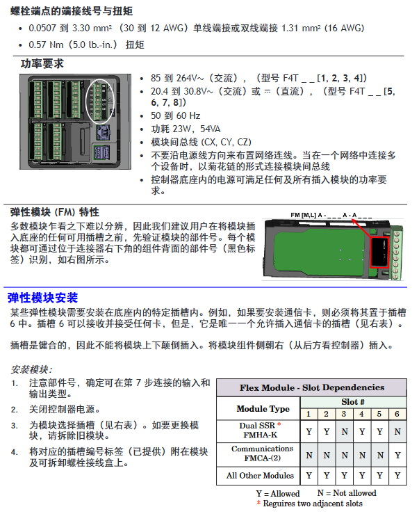
2. Terminal wiring requirements
Input terminal:
Wire diameter: 0.0507~3.30mm ² (30~12 AWG), double wire termination ≤ 1.31mm ² (16 AWG)
Torque: 0.57Nm (5.0 lb in), wire stripping length 5.5mm
Wire/load/ground terminal:
Wire diameter: 2.5~25mm ² (14~3 AWG)
Torque: 2.7Nm (24 lb in), wire stripping length 11mm; re tighten after 48 hours, every 3-6 months
Power wiring: Terminals 98 (+) and 99 (-) should follow NEC or local electrical regulations to avoid parallel wiring with power lines
3. Installation of Elastic Module (FM)
Slot dependency rules:
The communication module (FMCA series) can only be installed in slot 6;
The high-density dual SSR module (FMHA-KAAA) requires 2 adjacent slots and cannot be placed in slots 3/6;
The module needs to be inserted with the component side facing right, and the key design prevents reverse installation.
Module identification: Confirm the part number through the black label in the lower right corner of the connector (e.g. FMMA-UKAA-AAA is 1 universal input+1 SSR output).
Input/output wiring and module specifications
1. Input wiring (some key types)
Input type wiring requires accuracy and range
Connect the negative electrode (red wire) of the thermocouple to the S terminal; The compensating wire should be made of the same alloy as the thermocouple; Input impedance>20M Ω J-type: ± 1.75 ℃ (0~750 ℃); K-type: ± 2.45 ℃ (-200~1250 ℃)
RTD (Platinum) 2-wire/3-wire, 3-wire self compensating ≤ 10 Ω lead resistance; S1 (white line) connected to R1 100 Ω (0 ℃): ± 2.00 ℃ (-200~800 ℃); 1000Ω(0℃):±2.00℃(-200~800℃)
Digital input voltage input: ≤ 36V (3mA), ≥ 3V (0.25mA) activated; Dry contact: ≤ 100 Ω activated, ≥ 500 Ω inactive update rate 10Hz; maximum short-circuit current 13mA
Current transformer input 0~50mAac; Requires Watlow 16-0246 module; The load line needs to pass through the CT in the same direction with a response time of ≤ 1 second; Accuracy ± 1mA
2. Output wiring (some key types)
Output type wiring requirements specification parameters
Mechanical relay 240Vac/30VDC, 5A resistance load; Minimum 20mA load at 24V; When connecting Quencac (0804-0147-0000) 120/240Vac across coils, a guiding power of 125VA is required; Rated load 100000 cycles
Solid state relay (SSR) 24~264Vac, 0.5A at 149 ° F (65 ℃), 1A at 50 ° F (10 ℃); only AC load optically isolated; The maximum off state leakage current is 105 μ A; 20VA guidance power at 120/240Vac
Switching DC 22~32VDC open circuit voltage; 2 output combination current ≤ 40mA; when driving external SSR, connect to DC+/DC - short circuit limit<50mA; DIN-A-MITE compatible
Universal process output 0~10Vdc (minimum load of 1k Ω) or 0~20mA (maximum load of 800 Ω); Voltage/current output accuracy of ± 15mV (voltage)/± 30 μ A (current) cannot be used simultaneously; Temperature stability 100ppm/℃
Calibration and PC connection
1. Calibration operation
Calibration prerequisite: Accurate signal source is required (such as thermocouple 0.000~50.00mV, RTD 50.0~350.0 Ω). It is recommended to first verify whether the error exceeds the specifications (such as thermocouple ± 1.75 ℃).
Operation method:
Composer software: Connect device → Device menu → Calibration → Select module/input → Enter 2 limit values as prompted;
Front panel: Menu → Service → Calibration → Select module/input → Perform on-site calibration.
Notes:
The calibration values will be reset to factory settings and cleared;
3-wire RTD calibration requires cross connection of R, T, and S inputs;
The security settings are divided into "full access/read only/no access", and without access permission, the calibration screen cannot be accessed.
2. PC connection and Composer software
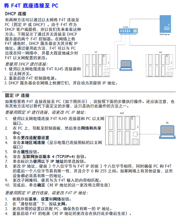
Ethernet settings:
Default parameters: IP 192.168.0.222, subnet 255.255.255.0, gateway 0.0.0.0;
DHCP connection: F4T is connected to the switch, and the DHCP server automatically assigns an IP address;
Fixed IP connection: PC is directly connected to F4T, and the first three segments of PC IP are consistent with F4T (such as 192.168.0. XXX).
Composer software:
Function: Configure elastic module (check if slot module matches), customize function block (alarm/timer/mathematical operation);
Troubleshooting and Maintenance
1. Common faults and solutions (partial)
Possible causes and solutions for the fault phenomenon
Alarm cannot be cleared/reset. 1. Alarm latch activation; 2. Alarm source setting error 1. Reset when the process is within range; 2. Select the correct input instance
No serial communication 1. Address/baud rate mismatch; 2. EIA-485 wiring error 1. Unified device protocol parameters; 2. T+/R+connected to B, T -/R - connected to A
Temperature runaway (overshoot/undershoot): 1. Thermoelectric dipole polarity reversal; 2. Heater short circuit: 1. Connect the red wire to the S terminal; 2. Replace the heater/repair the wiring
No display 1. Power off; 2. The fuse is open circuit; 3. Voltage error: 1. Check the circuit breaker/interlock; 2. Replace the fuse; 3. Confirm 24/240Vac
The process cannot reach the set point 1. The controller is not tuned; 2. Set the control mode to "off". 1. Perform automatic tuning; 2. Set as "PID" or "on-off"
2. Battery replacement
Battery specifications: Model BR2032 (Watlow part number 0830-0858-0000), nominal voltage 3V, lifespan of 10 years at 77 ° F (25 ℃), and replacement time of 7.5 years in harsh environments.
Replacement steps:
Turn off all power sources of F4T;
Use a small screwdriver to push out the battery holder from the side hole and remove the old battery (note the polarity clearly);
Insert the positive pole of the new battery to the left and reset the battery holder;
It is recommended to recycle used batteries and not dispose of them casually.
Model ordering rules (example: F4T11A1A1AA)
Example of optional values for field meanings
The first and second product series F4=T series controller
3rd basic type T=touch screen
4th application type 1=Standard, X=Custom
The 5th future option A=none, J=data record
6th power supply and connector 1=100~240Vac right angle connector (with identification)
The 7th and 8th bits of the configuration file and function block AA=no configuration file+basic function block
Customization options for positions 9-15 (connector/firmware/document) 1A=including DVD document+gray personalized border
Key issues
Question 1: What are the types of elastic modules (FM) for F4T controllers? What are the different types of core functions and slot installation rules?
Answer:
Types and core functions of elastic modules:
Hybrid I/O module (FMMA series): includes 1 universal input (supporting thermocouple/RTD/0~10V/0~20mA)+1 output (such as SSR, mechanical relay, switched DC), used for conventional temperature acquisition and load control, such as FMMA-UKAA-AAA (1 universal input+1 SSR output);
Restriction module (FMLA series): used for safety interlock control, including 1 input (universal/thermistor)+1-2 outputs (such as C-shaped relay, supporting normally closed interlock), such as FMLA-LCJ-AAA (restriction control with universal input+switched DC output);
High density I/O module (FMHA series): integrates multiple inputs/outputs, such as FMHA-RAAA-AAA (4 universal inputs), FMHA-JAAA-AAA (4 mechanical relay outputs), suitable for multi-channel acquisition and control scenarios;
Communication module (FMCA series): Only supports Modbus RTU protocol (EIA-232/485), used for serial communication between the controller and PLC/PC, such as FMCA-2AA-AAA.
Slot installation rules:
Exclusive slot: The communication module (FMCA series) can only be installed in slot 6 and cannot be recognized in other slots;
Multi slot requirement: Some high-density modules (such as dual SSR output FMHA-KAAA) require 2 adjacent slots and cannot be placed in slot 3 (single slot design);
Keying error prevention: The module has a keying structure and cannot be inserted upside down. The component side should face right (when viewed from the back of the controller);
Label requirement: After installation, slot number labels should be affixed to the module and junction box to avoid controller failure caused by inserting the wrong slot during replacement.
Question 2: How to correctly wire the thermocouple input of F4T controller? What steps should be followed when calibrating thermocouple inputs?
Answer:
Requirements for correct wiring of thermocouples:
Polarity differentiation: The negative lead of a thermocouple is usually red and must be connected to the S terminal (signal negative) of the module, while the positive lead is connected to the R terminal (signal positive). Reversing the connections can result in incorrect temperature readings;
Compensation wire: It is necessary to use a compensation wire made of the same alloy as the thermocouple (such as K-type compensation wire for K-type) to reduce the influence of ambient temperature on readings;
Insulation requirements: The input impedance of the thermocouple should be greater than 20M Ω, and the maximum source resistance should be 2k Ω. When wiring, it is necessary to avoid parallel wiring with the power line to prevent electromagnetic interference;
Open circuit detection: The module has a built-in 3 μ A open circuit sensor for detection. If the wiring is open, it will trigger an "incorrect input" alarm.
Thermocouple input calibration steps (using Composer software as an example):
Preparation equipment: high-precision millivolt signal source (if able to output 0.000~50.000mV), copper wire (to minimize wiring error), voltage/ohmmeter (to verify the accuracy of the signal source);
Software connection: Start Composer → Connect F4T (enter IP 192.168.0.222) → Enter "Device menu → Calibration";
Select channel: Select the module where the thermocouple is located and the input channel (such as input 1 of slot 1) in the "pluggable module";
Enter calibration value:
Input the lower limit signal (such as 0.000mV, corresponding to 0 ℃) to the module, enter the actual signal value in the software, and click "Calibrate Lower Limit";
Input the upper limit signal (such as 50.000mV, corresponding to approximately 1200 ℃, depending on the thermocouple type), input the actual value, and click "Calibrate Upper Limit";
Verification and saving: After calibration, input the intermediate value (such as 25.000mV) to the module, confirm that the displayed value and actual value error are ≤ specifications (such as J-type ± 1.75 ℃), and save the calibration data;
Attention: If the factory settings are restored after calibration, the calibration values will be cleared; The calibration of a 3-wire RTD requires crossing the R, T, and S terminals, and the lead resistance should be ≤ 10 Ω.
Question 3: What are the possible reasons for the F4T controller experiencing a "temperature runaway (continuous increase after process value overshoot)" fault? What are the corresponding troubleshooting and resolution steps?
Answer:
Possible reasons:
Output function setting error (such as heating output set to cooling);
Reverse wiring of thermocouple/RTD (e.g. thermocouple red wire connected to positive electrode, RTD S1 not connected to R1);
Controller output wiring error (such as SSR output L1/L2 reversed);
Heater or wiring short circuit (causing continuous power supply to the load);
Power controller connection defects (such as DIN-A-MITE and F4T signal interruption, unable to turn off the load);
The control algorithm is set to "on-off" and the hysteresis is too large (causing the heating to not stop in time).
Troubleshooting and resolution steps:
Check the output function settings:
Front panel: Menu → Settings → Output → Select the corresponding output channel, confirm that the "Function Type" is "Heating" (not "Cooling");
If there is an error, modify it to the correct type and restart the controller to take effect;
Verify sensor wiring:
Thermocouple: Disconnect the wiring, confirm that the red wire (negative electrode) is connected to the S terminal, the positive electrode is connected to the R terminal, and if the wiring is reversed, reconnect it;
RTD: 3 wire type needs to confirm S1 (white wire) connected to R1, T1 connected to S2, lead resistance ≤ 10 Ω (measured with an ohmmeter);
Check the output wiring and load:
After the power is cut off, use a multimeter to check the on/off switch of the heater wiring. If there is a short circuit, replace the heater;
Check SSR/relay output: output 100% power to the controller, measure the output terminal voltage (such as 240Vac), and the voltage should disappear after power failure. If there is continuous voltage, replace the SSR/relay;
Verify power controller connection:
If using a DIN-A-MITE power controller, check the signal lines between F4T and DIN-A-MITE (such as switched DC output) to ensure that there is no looseness/disconnection and that the signal can trigger DIN-A-MITE shutdown normally;
Adjust control algorithm:
If it is "on-off" control: menu → control → algorithm → change to "PID", execute automatic tuning (TRU-TUNE) ®+), Reduce overshoot;
If PID overshoot occurs: adjust the proportional band (increase) or integral time (extend) to reduce response speed;
Test validation:
Power on again, set the target temperature (such as 100 ℃), observe whether the process value stabilizes within the set point ± accuracy range (such as ± 1 ℃), and if it still loses control, troubleshoot the controller output hardware (such as replacing the output module).
- YOKOGAWA
- Reliance
- ADVANCED
- SEW
- ProSoft
- WATLOW
- Kongsberg
- FANUC
- VSD
- DCS
- PLC
- man-machine
- Covid-19
- Energy and Gender
- Energy Access
- Renewable Integration
- Energy Subsidies
- Energy and Water
- Net zero emission
- Energy Security
- Critical Minerals
- A-B
- petroleum
- Mine scale
- Sewage treatment
- cement
- architecture
- Industrial information
- New energy
- Automobile market
- electricity
- Construction site
- HIMA
- ABB
- Rockwell
- Schneider Modicon
- Siemens
- xYCOM
- Yaskawa
- Woodward
- BOSCH Rexroth
- MOOG
- General Electric
- American NI
- Rolls-Royce
- CTI
- Honeywell
- EMERSON
- MAN
- GE
- TRICONEX
- Control Wave
- ALSTOM
- AMAT
- STUDER
- KONGSBERG
- MOTOROLA
- DANAHER MOTION
- Bentley
- Galil
- EATON
- MOLEX
- Triconex
- DEIF
- B&W
- ZYGO
- Aerotech
- DANFOSS
- KOLLMORGEN
- Beijer
- Endress+Hauser
- schneider
- Foxboro
- KB
- REXROTH
- YAMAHA
- Johnson
- Westinghouse
- WAGO
- TOSHIBA
- TEKTRONIX
- BENDER
- BMCM
- SMC
- HITACHI
- HIRSCHMANN
- XP POWER
- Baldor
- Meggitt
- SHINKAWA
- Other Brands
- UniOP
- KUKA
- IBA
- Beckhoff
-
ADLINK CPCI-6860A - 51-31310-OB10 industrial motherboard CompactPCI SBC
-
ADLINK AmITX-SL-G-H110 - 51-7A104-0A30 Mini-ITX Industrial Motherboard
-
ADLINK PXI-2005-003 - CPCI Industrial PC Data Acquisition Card Multi-Function DAQ
-
ADLINK DININ-814M - 51-14032-0A3D SCSI-100P cable connection Interface Terminal Board
-
ADLINK CPCI-3920NA/C2D15/M1G - 3U CompactPCI Intel Core 2 Duo Single Board Computer
-
ADLINK PCIE-8560 - 51-18014-0A20 Communication Card High Speed DAQ
-
ADLINK PCI-C154+ - Motion Control Card 4-axis Motion Controller Board
-
ADLINK PCI-RTV24 - image capture card Analog Video Frame Grabber
-
ADLINK NuPRO-842LV/P - 51-41360-0B30 Industrial Motherboard CPU Board
-
ADLINK cBP-3208/3208R - CPCI Board 3U 8-Slot CompactPCI Backplane
-
ADLINK PCI-8164 - 4-Axis Motion Controller PCI Card 51-12406-0A40
-
ADLINK PCIe-GIE64+ - 4-CH GigE Vision PoE+ Frame Grabber Video Capture Card
-
ADLINK CPCI-6860 / 6860A - CompactPCI Dual Xeon Single Board Computer
-
ADLINK IEC-915GV - REV 1.1 Industrial motherboard CPU Board
-
ADLINK ND-6520 - Technology RS-232 to RS-422RS-485 Converter NuDAM Module
-
ADLINK RTV-24 / PCI-MP4S - 51-12519-1C30 4-Channel Real Time Video Capture Board
-
ADLINK cPCI-6910 / cPCI-6910AM/M1G - cPCI-6910AM/DXL16/M1G/S80G(G)-3120 BOARD CompactPCI SBC
-
ADLINK NUPRO-A40H - Linghua 51-41807-1A30 Industrial Control Computer Motherboard
-
ADLINK USB-3488A - USB to GPIB INTERFACE USB-3488A(G) Controller Module
-
ADLINK PCI-8134A - motion control card 4-Axis Controller Card
-
ADLINK PCI-7432 - Board 32-Channel input / 32-output Isolated Digital I/O PCI Card
-
ADLINK PCI-8134A - 51-12421-0A10 motion controller card tested
-
ADLINK LPCIe-7230 - 32 CH Isolated Input/output Card 2 Interrupts Low Profile PCIe
-
ADLINK NuPRO-E340 - industrial computer motherboard 51-47807-0A30 PICMG 1.3 SHB
-
ADLINK PCI-7434 - High-speed Digital Acquisition Card 64-CH Isolated DO Card
-
ADLINK NuPRO-E330 - 51-41805-0A20 Indsutrial Board SHB Single Board Computer
-
ADLINK PCI-7248 - OPTO-22 48 CHANNEL DIO DIGITAL TTL/DTL I/O 51-12006-0A40 GP
-
ADLINK PCI-8134 - Motion control card 4-Axis Controller Card
-
ADLINK AMP-208C - Movimiento Control Tarjeta 51-12420-1A20 W/Expansión & Breakout
-
ADLINK PCI-8164 - 51-12406-0A40 PCB Board 4-Axis Motion Controller Card
-
ADLINK DIN-68Y-SGII / DIN-68M-J3A - Terminal Board Connector Interface Block
-
ADLINK PCIe-7432 - Technology 51-18402-0A10 PCIe Card With High Input Range
-
ADLINK PCI-8144 / PCI-8144N - Motion control card 4-Axis Stepper Controller Card
-
ADLINK HSL-HUB3/REPEATER - HIGH SPEED LINK EXTENSION MODULES Distributed Hub Module
-
ADLINK ND-6017 - Data Logging + Acquisition 8CH A/D input Mod NuDAM Module
-
ADLINK LPCIe-7250 - data acquisition card Low Profile 8-CH Relay Output Card
-
ADLINK PCI-7432 - I/O card 64-CH Isolated Digital Input Output PCI Card
-
ADLINK IMB-M43H - industrial control computer motherboard Q87 Chip Micro-ATX
-
ADLINK MP-C154 - Motion control Card 4-Axis Motion Controller Board
-
ADLINK PCI-RTV24 - image capture card Video Frame Grabber Card
-
ADLINK PCI-7250 - 8-CH Relay Output & 8-CH Isolated DI Card
-
ADLINK PCI-6308V - 8-CH 12-Bit Isolated Analog Output PCI Card PCB-I-E-1148=6EX2
-
ADLINK PCI-7248 - capture card 48-CH Opto-22 Compatible DIO Card
-
ADLINK HSL-AI16A02-M-VV - Analog Input Output Distributed Module
-
ADLINK NuPRO-A301 - Rev:1.4 NUPRO-A301 PICMG Full-Size Single Board Computer
-
ADLINK PCI-6208V-GL - 8-CH Voltage Analog Output PCI Card
-
ADLINK PCI-8134A - 51-12421-0A10 4-Axis Motion Controller Card
-
ADLINK MNET-S23 - TECHNOLOGY MNET S23 - SERVO DRIVER CONTROL MODULE
-
ADLINK M-342 - ATX I3 I5 I7 Q67 Industrial Motherboard
-
ADLINK NUPRO-780 - Industrial Motherboard CPU Board PICMG SBC
-
ADLINK MP-C154 / MP-C152 - 4-Axis Motion Control Card Pulse-Train Controller
-
ADLINK NuPRO-935A/LV10B0 - Motherboard 51-41802-0A10 GP w/RAM Industrial Control Board
-
ADLINK MP-C154 - Motion control card 4-Axis Motion Controller Mainboard
-
ADLINK PCI-7250 - PCI Acquisition Card 8-CH Relay Output Isolated DI Card
-
ADLINK ACL-7124 - Technology Inc.24 DIO Card Digital Input Output Card
-
ADLINK PCI-8554 A2 - Timer/Counter Data Acquisition Card
-
ADLINK DIN-825-GP4 - Terminal Block Interface Board Breakout Module
-
ADLINK NuPR0-761 - REV:1.1 Industrial motherboard Full-Size PICMG SBC
-
ADLINK MXE-1401/M8G (G) - Matrix Fanless Embedded Computer Industrial PC
-
ADLINK HSL-DI16DO16-UD-NN - Digital 16 Channel I/O Mod Distributed I/O Module
-
ADLINK ND6520 - NUDAM INTELLIGENT DA&C MODULE RS232-RS-422/RS485 CONVERTOR
-
ADLINK NUPRO-761 - REV:1.1 Industrial Motherboard CPU Board
-
ADLINK AMP-208C - Motion Control Card 51-12420-1A20 DSP-based 8-axis
-
ADLINK NuPRO-A301REV 1.4 - with packaging industrial computer motherboard PICMG SBC
-
ADLINK PCM-9112+ - 51-12300-0A2 industrial motherboard Multi-Function DAQ PC/104 Module
-
ADLINK PCM-7250+ - 8-CH Relay Outputs & 8-CH Isolated DI Module PC/104
-
ADLINK PCI-RTV24 - Image capture card Analog Video Frame Grabber
-
ADLINK PCI-8134 - Motion Controller PCI Card 4-Axis Controller Board
-
ADLINK PCI-7432 - Isolated Digital I/O PCI Card
-
ADLINK PCI-8554 A2 - acquisition card Timer/Counter Card
-
ADLINK PCI-8132 - Rev.A2 2-Axis Servo & Stepper Motion Controller Card
-
ADLINK PCI-8132 - Data Acquisition card 2-Axis Motion Controller Card
-
ADLINK EBP-13E4 - 51-46703-0A30 Industrial Backplane Board Passive Backplane
-
ADLINK PCI-800L - Electronic Card Interface Controller Card
-
ADLINK PCIe-GIE72 - 51-18531-0A10 PCB Board GigE Vision Frame Grabber
-
ADLINK DAQ-2010(G)-OOBO - Simultaneous-Sampling Multi-Function DAQ Card
-
ADLINK PCI-9112 - REV.B1 Multifunction DAQ Card Data Acquisition Card
-
ADLINK PCI-7230 - 51-12003-DA60 32-CH Isolated Digital I/O Card
-
ADLINK PCI-7432 - Data Acquisition Card Isolated Digital I/O PCI Card
-
ADLINK ETX-AT-N270-18/LXE - 51-71111-0A20 ETX CPU Module Motherboard
-
ADLINK HSL-DI32-UD-N - DIGITAL INPUT 32 POINTS MODULE Distributed I/O
-
ADLINK AMP-204C - Motion Control card DSP-Based 4-Axis Advanced Controller
-
ADLINK MNET-4XMOG-0050 - Four-axis Motion Controller Distributed Motion Module
-
ADLINK AMP-204C - Motion control card DSP-Based 4-Axis Pulse-Train Controller
-
ADLINK PCI-7442 - Switch card 64-Channel Datalogging & Acquisition Card
-
ADLINK M-302 - Industrial control motherboard ATX PC Board
-
ADLINK NUPRO-852 / NUPRO-852LV - Industrial motherboard Single Board Computer
-
ADLINK PCI-8134 - REV.B1. 4-Axis Motion Controller Card
-
ADLINK PCI-GIE62 + - 51-18502-0A20 2-CH GigE Vision Frame Grabber PoE Card
-
ADLINK PCI-MPG24 - 51-12523-0B20 MPEG4 Card Video Compression Hardware
-
ADLINK HSL-TB32-M-DIN - 32-CH I/O TERMINAL W/ HSL-AI16AO2-M-VV MODULE
-
ADLINK PCI-M114-GL - PCB Ver 2.1 Motion Controller Axis Card
-
ADLINK IMB-M40H - SYM76996H61 motherboard Industrial Computer Mainboard
-
ADLINK NUPRO-A40H - 51-41807-1A20 industrial control motherboard H61 Chip
-
ADLINK PCI-M114-GL - Axis Card Data Acquisition Card PCB VER2.2 Motion Controller
-
ADLINK PCI-8134 - Motion Controller PCI Card 4-Axis Controller Board
-
ADLINK PCI-8102 - Motion control card 2-Axis Servo & Stepper Controller
-
ADLINK NuPRO-841REV:3.0 - motherboard Industrial Control PC Board
-
ADLINK HSL-TB32-U-DIN REV A1 - Breakout Terminal Board Field I/O Module
-
ADLINK AMP-204C - Motion Control card DSP-Based 4-Axis Pulse-Train Controller
-
ADLINK NUPRO-A40H - 51-41807-1A20 industrial control motherboard H61 PC Board
-
ADLINK PCI-6308A / PCI-6308V - 51-12202-0A50 Isolated Analog Output Card
-
ADLINK AMP-204C - DSP-Based 4-Axis Advanced Pulse-Train Motion Controller
-
ADLINK PCI-7434 - Technology 64-Channel Isolated Digital I/O PCI Cards
-
ADLINK CPCI-6840 / CPCI-6840V / PM16/M1G-12G0 - CompactPCI Single Board Computer CPU Module
-
ADLINK PCIE-GIE74 - Motherboard Video Capture Card 51-18531-0A10 Frame Grabber
-
ADLINK NuPRO-E330 - industrial computer equipment motherboard Control Mainboard
-
ADLINK AMP-208C / 51-12420-1A20 - Motion Control Card W/ Expansion & Breakout Board
-
ADLINK HPCI-14S12U - industrial computer baseboard Passive Backplane 14 Slots
-
ADLINK PCI-8164 - 4-Axis Motion Controller PCI Card W/ 1x Cable, 1x Breakout Box
-
ADLINK PCIe-RTV24 - 51-18016-0A20 Image Acquisition Video Capture Card
-
ADLINK M-342 - 5 PCI ATX Motherboard Industrial PC Mainboard
-
ADLINK PCI-FIW64 - 4/2 Channel IEEE1394B Image Capture Card FireWire Frame Grabber
-
ADLINK PCI-7432 - digital IO card 64-CH Isolated Digital Input Output Card
-
ADLINK 51-12001-0C20 - Circuit Board PCI-7200 Data Acquisition Controller Card
-
ADLINK PXI-3920 - PXI 3U cPCI Industrial Controller Embedded System CPU Board
-
ADLINK NuPRO-841REV:2.0 - motherboard Industrial Control PC Board
-
ADLINK NuPro-E330 - 51-41805-0A20 PCB Industrial Control Computer Motherboard
-
ADLINK PCI-RTV24 - Image capture card Analog Video Frame Grabber
-
ADLINK PCI-7442 - Switch card 64-Channel Datalogging & Acquisition Card
-
ADLINK HPX-13S4 - device baseboard Passive Backplane Riser Card
-
ADLINK PCI-9112 REV A.1 - Multi Function DA&C Board Data Acquisition Card
-
ADLINK PCI-7248 - 51-12006-0A40 Card Control 48-CH Digital I/O Module
-
ADLINK CPCI-6860 / 6860A - motherboard CompactPCI Dual Xeon Single Board Computer
-
ADLINK DPAC-3020-11(G) - Embedded PC Automation Controller Machine Control Board
-
ADLINK NuPRO-841 REV:1.0 - industrial control motherboard CPU Board
-
ADLINK MNET-4XMOG-0050 - Four-axis Motion Controller MNET Motion Control Card
-
ADLINK ETX-AT-N270-18/LXE - 51-71111-0A20 ETX CPU Module Motherboard

K-JIANG

Add: Jimei North Road, Jimei District, Xiamen, Fujian, China
Tell:+86-15305925923