
K-WANG


Watlow DIN-A-MITE ® Style C Solid State Power Controller
Watlow DIN-A-MITE ® Style C Solid State Power Controller
Product basic information and manufacturer background
1. Product positioning and manual usage
This product is an industrial grade solid-state power controller, with the model identification as "DIN-A-MITE ® Style C”, The manual clearly states that its core function is to guide users in completing product installation, wiring, parameter configuration, and safe operation and maintenance. It also includes specifications and recommended solutions for semiconductor fuses that users are concerned about, and emphasizes the need to follow national and local electrical safety regulations during installation.
2. Core configuration range of the product
Electrical basic parameters: Supports single-phase, three-phase 2-leg, and three-phase 3-leg (suitable for four wire star loads) configurations, with AC voltage coverage of 120-600V (ac) and current switching capability ranging from 30-80A depending on the model. Please refer to the output rated curve for specific specifications 🔶 1-9.
Control and protection options: Provide zero crossing variable time base or AC/DC input contactor versions, some zero crossing models have thyristor (SCR) short circuit protection and heater open circuit protection; Single phase models additionally support phase angle control and phase angle control with current limitation, and product configuration information can be directly identified through model coding.
Detailed technical specifications
1. General electrical parameters
(1) Current is related to power
Rated current: Please refer to the output rated curve on page 5. Different cooling methods (natural convection, fan cooling, through wall installation) and load types (resistive heater load) correspond to different rated values, and it is clear that the rated value is based on the resistive heater load 🔶 1-22.
Transient and limit current: The maximum peak surge current within 16.6 milliseconds is 1350A; the selection of fuses must meet the maximum value of 9100 A ² s for I ² t; The minimum latch current of SCR is 500mA, and the minimum holding current is 200mA to ensure stable triggering and operation of the device 🔶 1-24 🔶 1-25 🔶 1-26.
Auxiliary current and power consumption: The fan current varies depending on the power supply -0.14A at 24V (dc), 0.12A at 120V (ac), 0.06A at 240V (ac); the maximum off state leakage current is 1mA at 25 ° C (77 ° F); the power loss of each controlled branch is 1.2 watts/ampere (calculated based on switching ammeter) 🔶 1-28 🔶 1-29.
(2) Voltage range
Segmented by voltage level input range: 24-48V (ac) models with minimum 20V and maximum 53V; 120-240V (ac) models with minimum 48V and maximum 265V; 277-600V (ac) models with minimum 85V and maximum 660V, covering commonly used industrial voltage scenarios and adapting to different regional power grids 🔶 1-33 🔶 1-34.
(3) Environmental adaptability
The working humidity is 0-90% relative humidity (without condensation), and the storage temperature range is -40 to+85 ° C (-40 to 185 ° F); The insulation performance has only been tested below an altitude of 3000 meters, and additional evaluation is required for high-altitude scenarios 🔶 1-74 🔶 1-75; Simultaneously passing IEC 60068-2-32 (impact) and IEC 60068-2-6 (vibration) tests to ensure the anti-interference ability of industrial environments 🔶 1-59.
2. Operator interface and alarm function
(1) Interface configuration
Standard configuration includes command signal input and indicator lights, alarm output and indicator lights, and current limit indicator LEDs. Users can intuitively monitor the operating status of the equipment and quickly identify key working conditions such as signal input, alarm triggering, and current limit 🔶 1-18 🔶 1-19.
(2) Alarm function (limited to zero crossing models only)
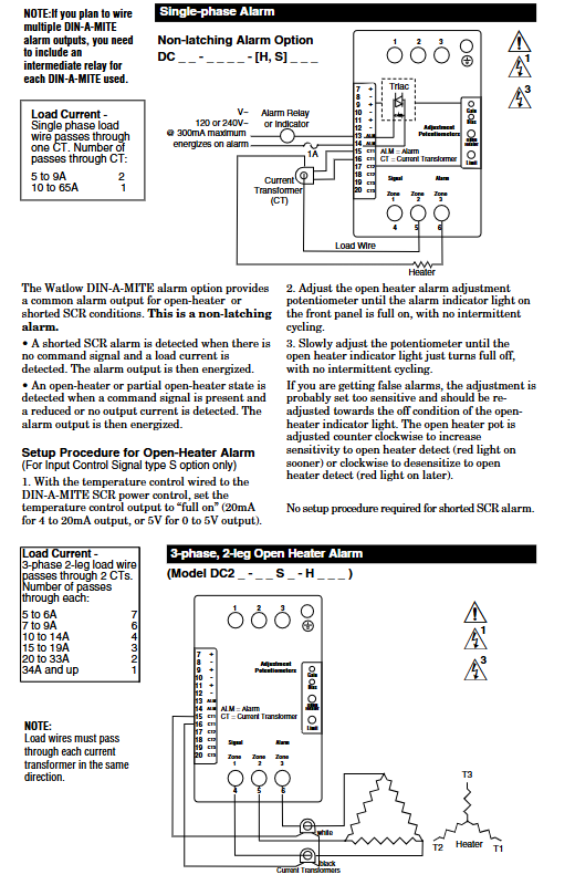
SCR short circuit alarm: When the input command signal is turned off, but the current transformer detects a load current of 10A or above, an alarm is triggered (2 turns of winding are required for 5A current, 3 turns of winding are required for 2.5A current), and the alarm state is an abnormal combination of "signal off+load current present".
Heater open circuit alarm: Only applicable to models with input control signal option "S". It is triggered when the input command signal is turned on, but the load current detected by the current transformer is lower than the alarm set value, covering the fault scenario of "signal on+insufficient current".
Alarm output characteristics: The alarm output is non latch type and is powered on when triggered; Adopting bidirectional thyristor (Triac) output, compatible with external power supply of 24-240V (ac), rated current varies at different temperatures -300mA at 25 ° C (77 ° F), 200mA at 50 ° C (122 ° F), 100mA at 80 ° C (176 ° F), typical holding current of 200 μ A, latch current of 5mA 🔶 1-42.
3. Certification and Security Compliance
International certification: meets ROHS environmental requirements; CE certification requires the use of appropriate filters to cover the 2004/108/EC Electromagnetic Compatibility Directive (EN 61326 Industrial Immunity Class A emission, not applicable to Class B environment) and the 2006/95/EC Low Voltage Directive (EN 50178 safety requirements), but phase angle and phase angle input control signal types with current limitation (P and L) do not have CE certification 🔶 1-45 🔶 1-46 🔶 1-47 🔶 1-48 🔶 1-49 🔶 1-50 🔶 1-51.
North American certification: UL ® 50 Type 4X shell certification, UL ANSI/ISA 12.12.01 temperature code T4A; The through wall heat sink component is suitable for Class I, Zone 2, Groups A, B, C, and D hazardous and non hazardous areas, but safety warnings such as "replacing any component may affect the applicability of hazardous areas" and "cannot be disconnected when the circuit is live unless the area confirms that there is no flammable concentration" are clearly stated 🔶 1-54 🔶 1-55 🔶 1-56; Simultaneously for UL ® 508 listed products, C-UL ® Document number E73741.
Installation specifications and size requirements
1. Installation method and steps
(1) DIN rail installation (DIN EN 50022, 35 × 7.5mm rail)
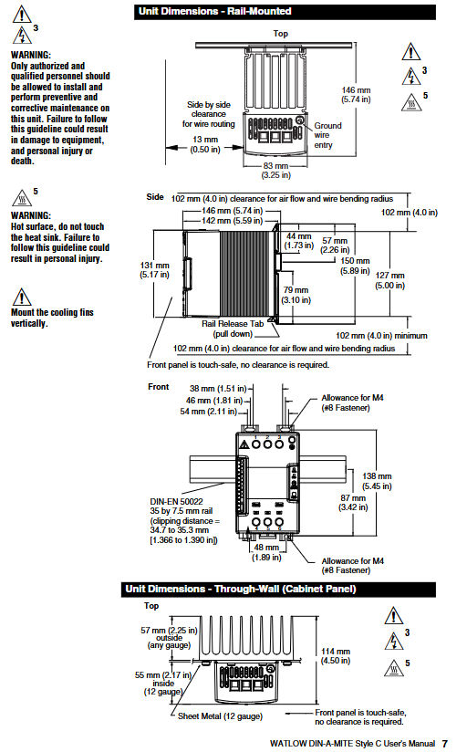
Installation steps: ① Push the device in and press down to clamp the top rail hook into the rail; ② Rotate the bottom of the device towards the guide rail; ③ The guide rail buckle will "click" to fasten. If it is not fastened, check whether the guide rail is bent; ④ The heat sink must be installed vertically (core requirement to ensure heat dissipation efficiency) 🔶 1-223 🔶 1-224 🔶 1-225.
Disassembly steps: Press and release the buckle, while rotating the device upwards and away from the guide rail to remove it.
Spacing requirement: A 102mm (4.0 inches) gap should be reserved on the side for airflow and wire bending radius; The front is designed with anti touch features, requiring no additional clearance; Minimum snap distance 34.8mm (1.37 inches), maximum 35.3mm (1.39 inches) 🔶 1-236 🔶 1-245.
(2) Panel installation
Four M4 (# 8) fasteners are required for fixation. Please refer to the panel installation dimension diagram on page 7 of the manual for specific dimensions, with a focus on the grounding wire entry position (13mm/0.50 inches) and the parallel arrangement wire gap (83mm/3.25 inches).
(3) Wall through installation (UL) ® 50 Type 4X Shell Model
Additional materials: 1 silicone gasket, 8 M5 screws and locking washers, 1 DIN-A-MITE C wall penetrating device 🔶 1-253 🔶 1-254 🔶 1-255.
Installation steps: ① Drill holes and cut the panel according to the size diagram on the right; ② Remove the mounting screws from the heat sink; ③ Tear off the protective film of the silicone gasket, attach the gasket to the heat sink, and ensure that the gasket hole is aligned with the heat sink screw hole; ④ Vertically install heat sink, torque controlled at 2.26-2.82 Nm (20-25 inch pounds) 🔶 1-257 🔶 1-258 🔶 1-259.
Size and Gap: The panel opening should meet the contour requirements of 178mm (7.00 inches) × 122mm (4.81 inches), and a minimum gap of 102mm (4.0 inches) should be reserved above and below the heat sink for airflow. A minimum gap of 10mm (0.4 inches) should be reserved on both sides.
2. Requirements for wiring terminals
(1) Input terminal (control signal type)
Adopting a crimping design, compatible with 0.2-1.5mm ² (24-16 AWG) wires; Use a 3.5mm (1/8 inch) flathead screwdriver and tighten to a torque of 0.5 Nm (4.4 inch pounds); The stripping length of the wire is 5.5mm (0.22 inches); The insulation level of the wire must be ≥ 75 ° C and is only applicable to copper conductors 🔶 1-61 🔶 1-62 🔶 1-63 🔶 1-64.
(2) Main circuit terminals (phase line, load, grounding)
Also of crimping type, compatible with 2.5-25mm ² (14-3 AWG) wires; Can be tightened with a 6.4mm (1/4 inch) flathead screwdriver or a 1A type # 2 Pozidriv screwdriver to a torque of 2.7 Nm (24 inch pounds); Wire stripping length 11mm (7/16 inches); Core maintenance requirement: Re tighten after 48 hours (to reduce wire cold flow), and then re tighten every 3-6 months thereafter 🔶 1-66 🔶 1-67 🔶 1-68 🔶 1-69 🔶 1-70.
(3) Cooling fan terminal
Adopting a quick connect design (1/8 inch push in), compatible with 16-14 AWG wires; Recommend using Amp part number 640929-1 or equivalent product 🔶 1-85.
Control mode and signal configuration
1. Zero crossing control mode (including contactor and proportional control)
(1) Type of contactor (input control signal)
DC input (Type C): 4.5-32V (DC) input, with a maximum current of 6mA per channel at 4.5V. An additional 2mA total current is required for each additional LED; To extend the service life, the cycle time should be less than 3 seconds 🔶 1-94.
AC input (Type K): Suitable for 24V (ac) ± 10%, 120V (ac)+10%/-25%, 240V (ac)+10%/-25%, with a maximum current of 25mA per circuit; it is strictly prohibited to share with temperature controllers with RC buffer circuits. If used, the RC buffer circuit must be removed first; Cycle time should be less than 3 seconds to extend lifespan 🔶 1-95 🔶 1-98.
(2) Proportional control (Type F, 4-20mA DC)
Variable time base control for loop power supply, only applicable to F0 input option; A current source of 8.0V (dc) or higher is required, with no more than 2 series inputs; Linearity requirements: Full open point 19.5-19.9mA (dc), maximum peak voltage 6.2V; Input output power accuracy ± 5% (0% -100% range, 4.3-19.7mA or 12.3-19.7mA); Temperature stability<0.15%/° C 🔶 1-96 🔶 1-102 🔶 1-105 🔶 1-106.
2. Phase angle and single cycle variable time base control
(1) Phase angle control (single-phase specific)
Applicable models: Type P (pure phase angle), Type L (phase angle with current limitation), only supports single-phase configuration, and has no alarm option 🔶 1-111.
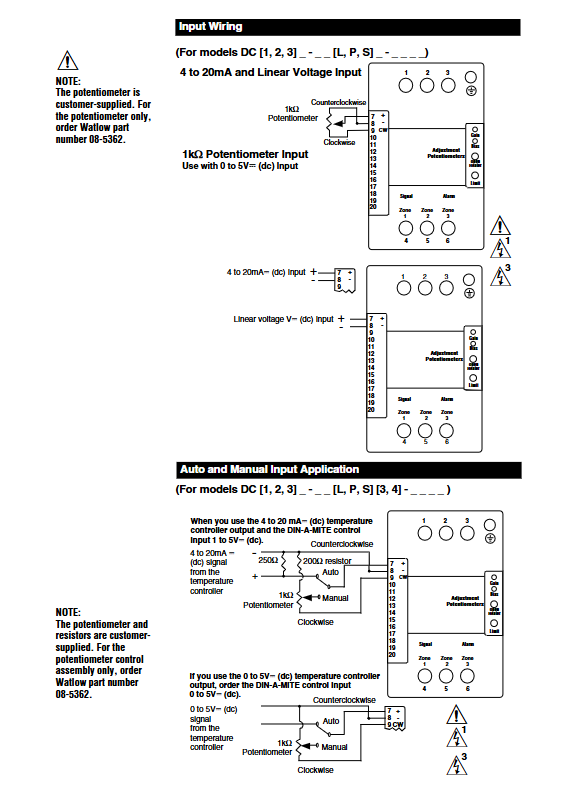
Input signal: Supports 0-20mA, 4-20mA, 12-20mA (DC) and 0-5V, 1-5V, 0-10V (DC); Input impedance: 4-20mA signal is 250 Ω, linear voltage signal is 5k Ω 🔶 1-112.
Output and accuracy: Output voltage covers 100-120V, 200-208V, 230-240V, 277V, 400V, 480V, 600V (ac), deviation -15%/+10%, frequency 50/60Hz (deviation ± 5%); At 25 ° C, the output conduction time is directly proportional to the command signal, with an accuracy of ± 5%; Temperature stability<0.25%/° C 🔶 1-115 🔶 1-117.
Soft start function: 5-second soft start when powered on, soft start when thermostat overtemperature occurs, soft start when half cycle dropout detection occurs, 1-second soft switching when set value changes, protecting load and devices 🔶 1-124 🔶 1-125 🔶 1-126.
(2) Single cycle variable time base (Type S)
Working logic: At 50% power, "1 cycle on, 1 cycle off"; At 25% power, "conduct for 1 cycle and close for 3 cycles"; Continuous conduction for no more than 1 cycle when power is less than 50%, and continuous shutdown for no more than 1 cycle when power is greater than 50% 🔶 1-110.
Accuracy and adaptability: The output power is proportional to the command signal at 25 ° C, with an accuracy of ± 5%; Temperature stability<0.25%/° C; supports linear voltage, 4-20mA or potentiometer input 🔶 1-120.
3. Resolution and Additional Options
Resolution: The accuracy of the output variation relative to the input range is greater than 0.1%.
Manual control kit: Optional 1k Ω single turn potentiometer (with 0-100% dial), part number 08-5362.
Ordering coding rules and current levels
1. Model code disassembly (complete code: DC+phase+cooling/current+voltage+control signal+alarm+language+customization)
Meaning and Options of Encoding Segments
DC prefix: Fixed identifier (DIN-A-MITE Style C)
Phase configuration 1=single-phase 1 controlled leg; 2=Three phase 2 controlled legs; 3=Three phase, three controlled legs (four wire star); 8=2 independent area; 9=3 independent areas
Cooling/current 0=natural convection (standard DIN rail/panel heat sink); 1=120V AC fan cooling; 2=240V AC fan cooling; 3=24V DC fan cooling; T=Natural convection (wall/cabinet type heat sink, UL 50)
Voltage level 02=24-48V AC (C/F/K control); 12=100-120V AC (L/P/S control); 20=200-208V AC (L/P/S control); 24=120-240V AC(C/F/K)/230-240V AC(L/P/S); 27=277V AC(L/P/S); 40=400V AC(L/P/S); 48=480V AC(L/P/S); 60=277-600V AC(C/F/K)/600V AC(L/P/S)
Control signal C0=4.5-32V DC contactor; K1=22-26V AC contactor; K2=100-120V AC contactor; K3=200-240V AC contactor; F0=4-20mA ratio (loop power supply); L (0-5)=phase angle with current limitation (single-phase); P (0-5)=phase angle (single-phase); S (0-5)=single cycle variable time base; Input types corresponding to 0-5 in parentheses: 0=4-20mA, 1=12-20mA (S only), 2=0-20mA, 3=0-5V DC, 4=1-5V DC, 5=0-10V DC
Alarm option 0=No alarm; S=SCR short circuit alarm (not applicable to 8/9 area or L/P control); H=heater open circuit+SCR short circuit alarm (only S control)
Manual language 0=English; 1=German; 2=Spanish; 3=French
Customized option 00=standard parts; 1X=1-second soft start (P/L control); XX=Custom Options/Identification
2. Current level table (by model prefix)
Model prefix Current level Remarks
DC10 55A natural convection (standard heat sink)
DC1T 62A natural convection (through wall/cabinet type heat sink)
DC11/DC12/DC13 75A fan cooling (120V AC/240V AC/24V DC)
DC20/DC80 40A three-phase 2-leg/2-zone, natural convection
DC2T/DC8T 46A three-phase 2-leg/2-zone, through wall heat sink
DC81/DC82/DC83/DC30/DC90 30A 2-zone fan cooling/three-phase 3-leg/3-zone natural convection
DC3T/DC9T 35A three-phase 3 leg/3 area, wall penetrating heat sink
DC31/DC32/DC33/DC91/DC92/DC93 55A three-phase 3 leg/3 zone, fan cooling
Selection of fuses and EMI filtering
1. Semiconductor fuse (suitable for applications with 600V AC and below)
Rated current of fuse Watlow fuse model Bussman fuse model Watlow bracket model Ferraz bracket model
30A 17-8030 FWP30A14F 17-5114 USM141i
40A 17-8040 FWP40A14F 17-5114 USM141i
50A 17-8050 FWP50A14F 17-5114 USM141i
63A 17-8063 FWP63A22F 17-5122 US221i
80A 17-8080 FWP80A22F 17-5122 US221i
100A 17-8100 FWP100A22F 17-5122 US221i
2. Combination fuse (suitable for applications with 600V AC and below)
Rated current of fuse Watlow, fuse model Bussman, Watlow bracket model Bussman, bracket model
30A 0808-0325-0030 DFJ30 0808-0326-1530 CH30J1i
40A 0808-0325-0040 DFJ40 0808-0325-3560 CH60J1i
50A 0808-0325-0050 DFJ50 0808-0325-3560 CH60J1i
63A 0808-0325-0060 DFJ60 0808-0325-3560 CH60J1i
80A 0808-0325-0080 DFJ80 0808-0325-7010 J60100-1CR
100A 0808-0325-0100 DFJ100 0808-0325-7010 J60100-1CR
3. EMI filtering requirements (electromagnetic interference suppression)
Mandatory scenario: When the load current is greater than 6A and the frequency is 150-250kHz, an external EMI filter must be used. Watlow verified that the "Tank Filter" can effectively suppress the EMI generated by the SCR power controller and meet the conducted emission limit.
Filter selection: For single-phase 230V (ac), choose Crydom 1F25 or Watlow 14-0019; Choose Crydom 3F20 or Watlow 14-0020 for three-phase 440V (ac); At the same time, a warning is issued that "slot filters may suppress useful communication in the 150-250kHz frequency band (such as baby monitors, medical alarm systems), and there is no safety risk that needs to be verified in advance" 🔶 1-437.
- YOKOGAWA
- Reliance
- ADVANCED
- SEW
- ProSoft
- WATLOW
- Kongsberg
- FANUC
- VSD
- DCS
- PLC
- man-machine
- Covid-19
- Energy and Gender
- Energy Access
- Renewable Integration
- Energy Subsidies
- Energy and Water
- Net zero emission
- Energy Security
- Critical Minerals
- A-B
- petroleum
- Mine scale
- Sewage treatment
- cement
- architecture
- Industrial information
- New energy
- Automobile market
- electricity
- Construction site
- HIMA
- ABB
- Rockwell
- Schneider Modicon
- Siemens
- xYCOM
- Yaskawa
- Woodward
- BOSCH Rexroth
- MOOG
- General Electric
- American NI
- Rolls-Royce
- CTI
- Honeywell
- EMERSON
- MAN
- GE
- TRICONEX
- Control Wave
- ALSTOM
- AMAT
- STUDER
- KONGSBERG
- MOTOROLA
- DANAHER MOTION
- Bentley
- Galil
- EATON
- MOLEX
- Triconex
- DEIF
- B&W
- ZYGO
- Aerotech
- DANFOSS
- KOLLMORGEN
- Beijer
- Endress+Hauser
- schneider
- Foxboro
- KB
- REXROTH
- YAMAHA
- Johnson
- Westinghouse
- WAGO
- TOSHIBA
- TEKTRONIX
- BENDER
- BMCM
- SMC
- HITACHI
- HIRSCHMANN
- XP POWER
- Baldor
- Meggitt
- SHINKAWA
- Other Brands
- UniOP
- KUKA
- IBA
- Beckhoff
-
ADLINK CPCI-6860A - 51-31310-OB10 industrial motherboard CompactPCI SBC
-
ADLINK AmITX-SL-G-H110 - 51-7A104-0A30 Mini-ITX Industrial Motherboard
-
ADLINK PXI-2005-003 - CPCI Industrial PC Data Acquisition Card Multi-Function DAQ
-
ADLINK DININ-814M - 51-14032-0A3D SCSI-100P cable connection Interface Terminal Board
-
ADLINK CPCI-3920NA/C2D15/M1G - 3U CompactPCI Intel Core 2 Duo Single Board Computer
-
ADLINK PCIE-8560 - 51-18014-0A20 Communication Card High Speed DAQ
-
ADLINK PCI-C154+ - Motion Control Card 4-axis Motion Controller Board
-
ADLINK PCI-RTV24 - image capture card Analog Video Frame Grabber
-
ADLINK NuPRO-842LV/P - 51-41360-0B30 Industrial Motherboard CPU Board
-
ADLINK cBP-3208/3208R - CPCI Board 3U 8-Slot CompactPCI Backplane
-
ADLINK PCI-8164 - 4-Axis Motion Controller PCI Card 51-12406-0A40
-
ADLINK PCIe-GIE64+ - 4-CH GigE Vision PoE+ Frame Grabber Video Capture Card
-
ADLINK CPCI-6860 / 6860A - CompactPCI Dual Xeon Single Board Computer
-
ADLINK IEC-915GV - REV 1.1 Industrial motherboard CPU Board
-
ADLINK ND-6520 - Technology RS-232 to RS-422RS-485 Converter NuDAM Module
-
ADLINK RTV-24 / PCI-MP4S - 51-12519-1C30 4-Channel Real Time Video Capture Board
-
ADLINK cPCI-6910 / cPCI-6910AM/M1G - cPCI-6910AM/DXL16/M1G/S80G(G)-3120 BOARD CompactPCI SBC
-
ADLINK NUPRO-A40H - Linghua 51-41807-1A30 Industrial Control Computer Motherboard
-
ADLINK USB-3488A - USB to GPIB INTERFACE USB-3488A(G) Controller Module
-
ADLINK PCI-8134A - motion control card 4-Axis Controller Card
-
ADLINK PCI-7432 - Board 32-Channel input / 32-output Isolated Digital I/O PCI Card
-
ADLINK PCI-8134A - 51-12421-0A10 motion controller card tested
-
ADLINK LPCIe-7230 - 32 CH Isolated Input/output Card 2 Interrupts Low Profile PCIe
-
ADLINK NuPRO-E340 - industrial computer motherboard 51-47807-0A30 PICMG 1.3 SHB
-
ADLINK PCI-7434 - High-speed Digital Acquisition Card 64-CH Isolated DO Card
-
ADLINK NuPRO-E330 - 51-41805-0A20 Indsutrial Board SHB Single Board Computer
-
ADLINK PCI-7248 - OPTO-22 48 CHANNEL DIO DIGITAL TTL/DTL I/O 51-12006-0A40 GP
-
ADLINK PCI-8134 - Motion control card 4-Axis Controller Card
-
ADLINK AMP-208C - Movimiento Control Tarjeta 51-12420-1A20 W/Expansión & Breakout
-
ADLINK PCI-8164 - 51-12406-0A40 PCB Board 4-Axis Motion Controller Card
-
ADLINK DIN-68Y-SGII / DIN-68M-J3A - Terminal Board Connector Interface Block
-
ADLINK PCIe-7432 - Technology 51-18402-0A10 PCIe Card With High Input Range
-
ADLINK PCI-8144 / PCI-8144N - Motion control card 4-Axis Stepper Controller Card
-
ADLINK HSL-HUB3/REPEATER - HIGH SPEED LINK EXTENSION MODULES Distributed Hub Module
-
ADLINK ND-6017 - Data Logging + Acquisition 8CH A/D input Mod NuDAM Module
-
ADLINK LPCIe-7250 - data acquisition card Low Profile 8-CH Relay Output Card
-
ADLINK PCI-7432 - I/O card 64-CH Isolated Digital Input Output PCI Card
-
ADLINK IMB-M43H - industrial control computer motherboard Q87 Chip Micro-ATX
-
ADLINK MP-C154 - Motion control Card 4-Axis Motion Controller Board
-
ADLINK PCI-RTV24 - image capture card Video Frame Grabber Card
-
ADLINK PCI-7250 - 8-CH Relay Output & 8-CH Isolated DI Card
-
ADLINK PCI-6308V - 8-CH 12-Bit Isolated Analog Output PCI Card PCB-I-E-1148=6EX2
-
ADLINK PCI-7248 - capture card 48-CH Opto-22 Compatible DIO Card
-
ADLINK HSL-AI16A02-M-VV - Analog Input Output Distributed Module
-
ADLINK NuPRO-A301 - Rev:1.4 NUPRO-A301 PICMG Full-Size Single Board Computer
-
ADLINK PCI-6208V-GL - 8-CH Voltage Analog Output PCI Card
-
ADLINK PCI-8134A - 51-12421-0A10 4-Axis Motion Controller Card
-
ADLINK MNET-S23 - TECHNOLOGY MNET S23 - SERVO DRIVER CONTROL MODULE
-
ADLINK M-342 - ATX I3 I5 I7 Q67 Industrial Motherboard
-
ADLINK NUPRO-780 - Industrial Motherboard CPU Board PICMG SBC
-
ADLINK MP-C154 / MP-C152 - 4-Axis Motion Control Card Pulse-Train Controller
-
ADLINK NuPRO-935A/LV10B0 - Motherboard 51-41802-0A10 GP w/RAM Industrial Control Board
-
ADLINK MP-C154 - Motion control card 4-Axis Motion Controller Mainboard
-
ADLINK PCI-7250 - PCI Acquisition Card 8-CH Relay Output Isolated DI Card
-
ADLINK ACL-7124 - Technology Inc.24 DIO Card Digital Input Output Card
-
ADLINK PCI-8554 A2 - Timer/Counter Data Acquisition Card
-
ADLINK DIN-825-GP4 - Terminal Block Interface Board Breakout Module
-
ADLINK NuPR0-761 - REV:1.1 Industrial motherboard Full-Size PICMG SBC
-
ADLINK MXE-1401/M8G (G) - Matrix Fanless Embedded Computer Industrial PC
-
ADLINK HSL-DI16DO16-UD-NN - Digital 16 Channel I/O Mod Distributed I/O Module
-
ADLINK ND6520 - NUDAM INTELLIGENT DA&C MODULE RS232-RS-422/RS485 CONVERTOR
-
ADLINK NUPRO-761 - REV:1.1 Industrial Motherboard CPU Board
-
ADLINK AMP-208C - Motion Control Card 51-12420-1A20 DSP-based 8-axis
-
ADLINK NuPRO-A301REV 1.4 - with packaging industrial computer motherboard PICMG SBC
-
ADLINK PCM-9112+ - 51-12300-0A2 industrial motherboard Multi-Function DAQ PC/104 Module
-
ADLINK PCM-7250+ - 8-CH Relay Outputs & 8-CH Isolated DI Module PC/104
-
ADLINK PCI-RTV24 - Image capture card Analog Video Frame Grabber
-
ADLINK PCI-8134 - Motion Controller PCI Card 4-Axis Controller Board
-
ADLINK PCI-7432 - Isolated Digital I/O PCI Card
-
ADLINK PCI-8554 A2 - acquisition card Timer/Counter Card
-
ADLINK PCI-8132 - Rev.A2 2-Axis Servo & Stepper Motion Controller Card
-
ADLINK PCI-8132 - Data Acquisition card 2-Axis Motion Controller Card
-
ADLINK EBP-13E4 - 51-46703-0A30 Industrial Backplane Board Passive Backplane
-
ADLINK PCI-800L - Electronic Card Interface Controller Card
-
ADLINK PCIe-GIE72 - 51-18531-0A10 PCB Board GigE Vision Frame Grabber
-
ADLINK DAQ-2010(G)-OOBO - Simultaneous-Sampling Multi-Function DAQ Card
-
ADLINK PCI-9112 - REV.B1 Multifunction DAQ Card Data Acquisition Card
-
ADLINK PCI-7230 - 51-12003-DA60 32-CH Isolated Digital I/O Card
-
ADLINK PCI-7432 - Data Acquisition Card Isolated Digital I/O PCI Card
-
ADLINK ETX-AT-N270-18/LXE - 51-71111-0A20 ETX CPU Module Motherboard
-
ADLINK HSL-DI32-UD-N - DIGITAL INPUT 32 POINTS MODULE Distributed I/O
-
ADLINK AMP-204C - Motion Control card DSP-Based 4-Axis Advanced Controller
-
ADLINK MNET-4XMOG-0050 - Four-axis Motion Controller Distributed Motion Module
-
ADLINK AMP-204C - Motion control card DSP-Based 4-Axis Pulse-Train Controller
-
ADLINK PCI-7442 - Switch card 64-Channel Datalogging & Acquisition Card
-
ADLINK M-302 - Industrial control motherboard ATX PC Board
-
ADLINK NUPRO-852 / NUPRO-852LV - Industrial motherboard Single Board Computer
-
ADLINK PCI-8134 - REV.B1. 4-Axis Motion Controller Card
-
ADLINK PCI-GIE62 + - 51-18502-0A20 2-CH GigE Vision Frame Grabber PoE Card
-
ADLINK PCI-MPG24 - 51-12523-0B20 MPEG4 Card Video Compression Hardware
-
ADLINK HSL-TB32-M-DIN - 32-CH I/O TERMINAL W/ HSL-AI16AO2-M-VV MODULE
-
ADLINK PCI-M114-GL - PCB Ver 2.1 Motion Controller Axis Card
-
ADLINK IMB-M40H - SYM76996H61 motherboard Industrial Computer Mainboard
-
ADLINK NUPRO-A40H - 51-41807-1A20 industrial control motherboard H61 Chip
-
ADLINK PCI-M114-GL - Axis Card Data Acquisition Card PCB VER2.2 Motion Controller
-
ADLINK PCI-8134 - Motion Controller PCI Card 4-Axis Controller Board
-
ADLINK PCI-8102 - Motion control card 2-Axis Servo & Stepper Controller
-
ADLINK NuPRO-841REV:3.0 - motherboard Industrial Control PC Board
-
ADLINK HSL-TB32-U-DIN REV A1 - Breakout Terminal Board Field I/O Module
-
ADLINK AMP-204C - Motion Control card DSP-Based 4-Axis Pulse-Train Controller
-
ADLINK NUPRO-A40H - 51-41807-1A20 industrial control motherboard H61 PC Board
-
ADLINK PCI-6308A / PCI-6308V - 51-12202-0A50 Isolated Analog Output Card
-
ADLINK AMP-204C - DSP-Based 4-Axis Advanced Pulse-Train Motion Controller
-
ADLINK PCI-7434 - Technology 64-Channel Isolated Digital I/O PCI Cards
-
ADLINK CPCI-6840 / CPCI-6840V / PM16/M1G-12G0 - CompactPCI Single Board Computer CPU Module
-
ADLINK PCIE-GIE74 - Motherboard Video Capture Card 51-18531-0A10 Frame Grabber
-
ADLINK NuPRO-E330 - industrial computer equipment motherboard Control Mainboard
-
ADLINK AMP-208C / 51-12420-1A20 - Motion Control Card W/ Expansion & Breakout Board
-
ADLINK HPCI-14S12U - industrial computer baseboard Passive Backplane 14 Slots
-
ADLINK PCI-8164 - 4-Axis Motion Controller PCI Card W/ 1x Cable, 1x Breakout Box
-
ADLINK PCIe-RTV24 - 51-18016-0A20 Image Acquisition Video Capture Card
-
ADLINK M-342 - 5 PCI ATX Motherboard Industrial PC Mainboard
-
ADLINK PCI-FIW64 - 4/2 Channel IEEE1394B Image Capture Card FireWire Frame Grabber
-
ADLINK PCI-7432 - digital IO card 64-CH Isolated Digital Input Output Card
-
ADLINK 51-12001-0C20 - Circuit Board PCI-7200 Data Acquisition Controller Card
-
ADLINK PXI-3920 - PXI 3U cPCI Industrial Controller Embedded System CPU Board
-
ADLINK NuPRO-841REV:2.0 - motherboard Industrial Control PC Board
-
ADLINK NuPro-E330 - 51-41805-0A20 PCB Industrial Control Computer Motherboard
-
ADLINK PCI-RTV24 - Image capture card Analog Video Frame Grabber
-
ADLINK PCI-7442 - Switch card 64-Channel Datalogging & Acquisition Card
-
ADLINK HPX-13S4 - device baseboard Passive Backplane Riser Card
-
ADLINK PCI-9112 REV A.1 - Multi Function DA&C Board Data Acquisition Card
-
ADLINK PCI-7248 - 51-12006-0A40 Card Control 48-CH Digital I/O Module
-
ADLINK CPCI-6860 / 6860A - motherboard CompactPCI Dual Xeon Single Board Computer
-
ADLINK DPAC-3020-11(G) - Embedded PC Automation Controller Machine Control Board
-
ADLINK NuPRO-841 REV:1.0 - industrial control motherboard CPU Board
-
ADLINK MNET-4XMOG-0050 - Four-axis Motion Controller MNET Motion Control Card
-
ADLINK ETX-AT-N270-18/LXE - 51-71111-0A20 ETX CPU Module Motherboard

K-JIANG

Add: Jimei North Road, Jimei District, Xiamen, Fujian, China
Tell:+86-15305925923