
K-WANG


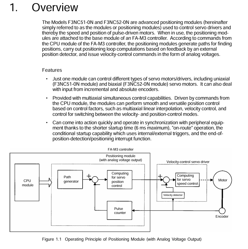
YOKOGAWA FA-M3 positioning module (with analog voltage output)
Document identification: Document number IM 34M6H58-01E, document model code DOCIM. This number must be referenced for communication and additional manual purchases; The media number is the same as the document number (CD version), and the copyright belongs to Yokogawa Electric in 1998.
YOKOGAWA FA-M3 positioning module (with analog voltage output)
Basic information and important statements
1. Applicable product and document identification
Applicable products: FA-M3 series unlimited range multi controller, specific models F3NC51-0N (single axis positioning module) and F3NC52-0N (dual axis positioning module), with the function of positioning control with analog voltage output.
Document identification: Document number IM 34M6H58-01E, document model code DOCIM. This number must be referenced for communication and additional manual purchases; The media number is the same as the document number (CD version), and the copyright belongs to Yokogawa Electric in 1998.
2. Important statement
Manual transmission: It needs to be transmitted to the end user. Before using the module, it is necessary to read the manual thoroughly to fully understand the product.
Content limitation: The manual only describes product functions and does not guarantee compatibility with specific user purposes; Without permission, partial or complete transcription or reproduction is not allowed; The content may change without prior notice.
Error feedback: Although we try our best to ensure the accuracy of the content, if any errors or omissions are found, please contact the nearest representative office or sales office of Yokogawa Electric.
Disclaimer: Yokogawa Electric only guarantees the product according to the separately provided warranty terms and is not responsible for direct/indirect losses caused by user use or unforeseeable defects of the product; The software is only for use on designated computers and is prohibited from reverse engineering, unauthorized transfer, etc.
Safety precautions
1. Definition of safety symbols
Meaning and usage scenarios of symbol types
CAUTION (product/manual) should follow the instructions in the manual to avoid personal injury, equipment damage, and other hazards such as electric shock prevention; The symbol in the manual is also used to indicate key information for understanding operations and functions
Warning (manual only): Please refer to the manual instructions to prevent hardware/software damage or system failure
TIP (manual only) provides information to supplement the current topic
SEE ALSO (manual only) indicates other sources of information to be referenced
2. Core security requirements
Grounding requirements: The functional grounding terminal (FG) must be grounded before use, and it must independently comply with Japanese Industrial Standards (JIS) Class 3 grounding, with a grounding resistance not exceeding 100 Ω, and avoid being grounded together with high-voltage power lines.
Installation environment: Avoid installation in locations with direct sunlight, temperatures exceeding 0-55 ℃, humidity exceeding 10% -90% (prone to condensation), corrosive/flammable gases, and mechanical vibrations/impacts.
Operation specification: The power must be turned off before installing/disassembling the module; Tighten the installation screws and terminal screws of the module to ensure that the interconnection cable connectors are secure and checked before powering on; An emergency stop circuit needs to be constructed using external relays to interlock with the controller status (stop/run); Avoid cleaning with solvents such as paint thinner, only wipe with a damp cloth or neutral cleaner.
Component replacement and modification: Only company designated components can be used for replacement, and it is prohibited to modify or add components to the interior of the product; The CPU module contains a built-in battery and should be stored in high temperature (storage temperature -20-75 ℃) and high humidity environments to prevent a sudden decrease in battery life.
Electrostatic protection: Before operating in a dry environment, touch the grounded metal to release static electricity.
Product specifications
1. General specifications (core parameters)
Project F3NC51-0N (single axis) F3NC52-0N (dual axis) Description
Control the number of axes: 1 axis and 2 axes-
Control method based on encoder feedback semi closed loop control based on encoder feedback semi closed loop control-
Analog voltage output -10~10V -10~10V for speed control commands
Encoder compatibility incremental encoder (A/B phase, RS422 differential input, maximum 2Mpps at 4x); Absolute encoders (Yokogawa ∑ series, Sanyo Electric Manchester encoder series, etc., see Section 2.4 for details) are the same as single axis encoders-
Control mode position control, speed control, speed position control mode switching are the same as single axis-
Position control function axis independent interpolation, multi axis linear interpolation, dual axis arc interpolation; Pulse range -134217728~134217727 pulses; Pulse frequency ranging from 0.1 to 200000 pulses per second; Support absolute/relative position selection, operation in the path, target position/speed change during operation, manual pulse generator axis stepping with single axis-
Pulse frequency range for speed control function -2000000 to 2000000 pulses per second; Support speed changes during operation on the same single axis-
Acceleration and deceleration methods include trapezoidal, two-stage, and S-shaped (three-stage) tracking, with single axis acceleration and deceleration times ranging from 0 to 32767ms each
Origin search can be defined through the origin setting value and external triggering; Search speed: Users can set the same single axis-
External contact input limit switch, driver alarm, origin, external trigger, universal input, emergency stop contact are the same as single axis 24V DC, 4.1mA
External contact output servo ON, driver reset, brake OFF contacts are the same as single axis 24V DC, 0.1A
Data backup is handled by the CPU module on the same single axis-
Start time maximum 6ms maximum 6ms-
Current consumption 5V DC, 390mA 5V DC, 400mA-
External power supply 24V DC, 10mA 24V DC, 10mA-
External wiring 40 pin connector (1) 40 pin connector (2)-
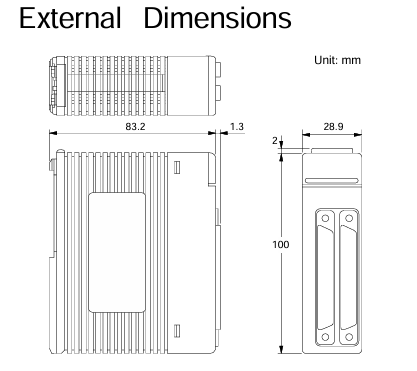
Dimensions: 28.9 (width) x 100 (height) x 83.2 (depth) mm (excluding protrusions) Same as single axis-
Weight 130g 140g-
2. Model and suffix code
Model code suffix code type remarks
F3NC51-0N single axis position loop control, -10~10V voltage output, maximum speed 2Mpps
F3NC52-0N dual axis position loop control, -10~10V voltage output, maximum speed 2Mpps
3. Applicable encoders
Universal two-phase rotary encoder;
Yokogawa Motor serial absolute encoder (such as ∑ series);
Sanyo Motor serial absolute encoder (such as P series) or compatible models (such as Panasonic MINAS series, Manchester encoded serial transmission).
4. Module components and indicator lights
F3NC51-0N (single axis): RDY indicator light (always on when the internal circuit is normal), ERR1 indicator light (lit when an error occurs), 40 pin connector (connected to external I/O devices such as servo motors and limit switches).
F3NC52-0N (dual axis): RDY indicator light (normally lit), ERR1 indicator light (lit up for axis 1 error), ERR2 indicator light (lit up for axis 2 error), 2 40 pin connectors (corresponding to external device connections for axis 1 and axis 2 respectively).
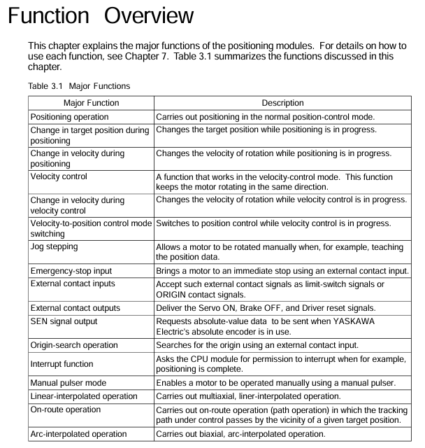
Function Overview
The core functions of the module revolve around the position control, speed control, and mode switching of the motor, supporting various flexible operations, as follows:
Function Name Core Description Operation Points
The positioning operation is performed according to the instructions of the CPU module. After setting the target position, speed, acceleration and deceleration parameters, the "start operation instruction" relay is triggered. After the positioning is completed, the "positioning end" relay can be set to absolute/relative position; The acceleration and deceleration curves can be trapezoidal, two-stage, or S-shaped; Can set the positioning judgment range and timeout period; Support normal startup or waiting for internal/external trigger startup
Target position change during positioning operation, writing new positioning parameters and triggering the "Target Position Change Request" relay, can synchronously change speed, supports direction change (motor first stops urgently and then locates towards the new target position)-
Speed change during positioning operation, writing new target speed and triggering the "speed change request" relay to achieve real-time speed adjustment-
Speed control writes parameters such as target speed (negative speed corresponds to reverse rotation), acceleration and deceleration time, triggering the "start operation command" relay. The motor continues to rotate and needs to be terminated through "deceleration stop request" or "immediate stop request". Only incremental encoders are supported; Acceleration and deceleration curves are the same as positioning operations; Support normal startup or waiting for internal/external trigger startup
Speed change in speed control. During speed control operation, writing a new target speed and triggering the "speed change request" relay does not support direction change (need to slow down and stop first, then reset direction to start)-
Switching between speed and position control modes: During the operation of speed control, parameters such as target position, speed, acceleration and deceleration are written to trigger the mode switching command. The positioning operation can be set to normal switching or wait for external triggering switching when the instantaneous position is set to "0"; Support detection of Z-phase signal switching (Z-phase polarity and counting frequency need to be set)
Writing parameters such as target speed and acceleration/deceleration time in jog step, triggering the "positive jog step" or "negative jog step" relay. When the relay is disconnected, the motor decelerates and stops according to the parameters, which only takes effect when there are no errors, servo ON, positioning end, position control mode, and no other instructions are executed; Can only be terminated by "stop immediately", cannot be stopped by "slow down"
The emergency stop input module includes one emergency stop input (dedicated to the 1-axis connector, shared by both axes), which is a B-contact input and must be wired. Otherwise, the module will not work and the motor will stop immediately after triggering-
External contact input: 6 external contact inputs, functions can be defined through the "contact input mode" (such as limit, alarm, origin, trigger, etc.), polarity can be set separately, and status can be read through the application program-
External contact outputs 3 external contact outputs (servo ON, brake OFF, driver reset), triggered by corresponding commands, polarity can be set separately, and status can be read through the application program-
The SEN signal output is only used to connect the Yokogawa Motor absolute encoder and request the transmission of absolute value data. Other drivers need to be suspended when connected-
The origin search operation writes parameters such as search direction, speed, mode (contact input detection action), Z-phase edge selection, etc., triggering the "origin search" relay. After detecting the preset external contact input or Z-phase signal, it decelerates and stops. The detection position can be used as the origin (or origin offset value) to adjust parameters in multiple cycles to achieve complex search; In the absolute encoder system, the Yokogawa method can be searched with the incremental encoder, while the Sanyo method cannot be searched
The interrupt function supports "position detection interrupt" (interrupts the CPU when the instruction/encoder position reaches the set value) and "positioning end interrupt" (interrupts the CPU when positioning is completed). Please refer to the CPU manual for handling interrupts-
After triggering the "Manual Pulse Generator Mode ON" in manual pulse generator mode, the motor is controlled by the manual pulse generator, and the ratio of pulse input to motor movement is set by the "Manual Pulse Generator Proportional Value"; Dual axis can be set to this mode simultaneously, and the shared pulse input cannot control the motor through CPU instructions in this mode; Restore position control after mode OFF
Linear interpolation operation simultaneously writes target speed, position, acceleration and deceleration parameters in both axes (with the same acceleration and deceleration time, speed ratio=movement ratio), synchronously triggers the "start operation command" relay, and after each axis completes positioning, the corresponding "positioning end" relay acts-
Starting a new positioning operation during the operation of positioning in the path, the new operation is initiated before the end of the current operation, forming a path overlap (interval in the path), without the need to stop at the middle target position, and supporting direction changes requires determining the start timing through the "remaining deceleration time" status to avoid operation conflicts
The arc interpolation operation writes parameters such as the center position, radius, starting angle, and angle movement in both axes, synchronously triggering the "start operation command" relay. The module generates the arc path through trigonometric functions to ensure that the X/Y axis parameters are consistent (starting angle, angle movement, etc.); When a single axis error occurs, the other axis continues to run, and the program needs to detect the error and stop it
Parameter settings
The module parameters are divided into entrance parameters (usually set only once after power on), startup parameters (reference for instructions such as positioning/speed control execution), origin search related startup parameters, extended instruction parameters, control mode switching parameters, and arc interpolation parameters. The core parameters are as follows:
1. Entrance parameters (key items)
Parameter Name Axis 1 Data Position Axis 2 Data Position Initial Value Range/Description
Positive limit value 001/002 201/202 134217727-134217728~134217727 pulse, set the position limit within the physical stroke
Negative limit value 003/004 203/204-134217728-134217728- (positive limit value -1) pulse
Speed limit value 005/006 205/206 131072000~131072000 (1/65536) pulse/ms, limit path generation speed
Overspeed detection value 007/008 207/208 131072000~131072000 (1/65536) pulse/ms, detecting the actual speed of the motor exceeding the limit
Super acceleration detection value 009/010 209/210 131072000~131072000 (1/65536) pulse/ms/ms, detecting actual motor acceleration exceeding the limit
Deviation error detection value 011/012 211/212 134217727 1~134217727 pulses, detecting that the deviation between the instruction position and the encoder feedback position exceeds the limit
Motor rotation direction 013 213 0 0: Positive speed command voltage corresponds to forward rotation; 1: Positive speed command voltage corresponds to reverse rotation
Encoder specification 018 218 0 0: Universal incremental type; 1: Sanyo Manchester encoding absolute formula; 2: Yokogawa Serial Absolute Formula
Speed/voltage ratio 020/021 220/221 10240 1~2000000 pps/V, calculation formula: (rated motor speed x encoder pulses/minute) ÷ rated voltage
2. Other parameters (core items)
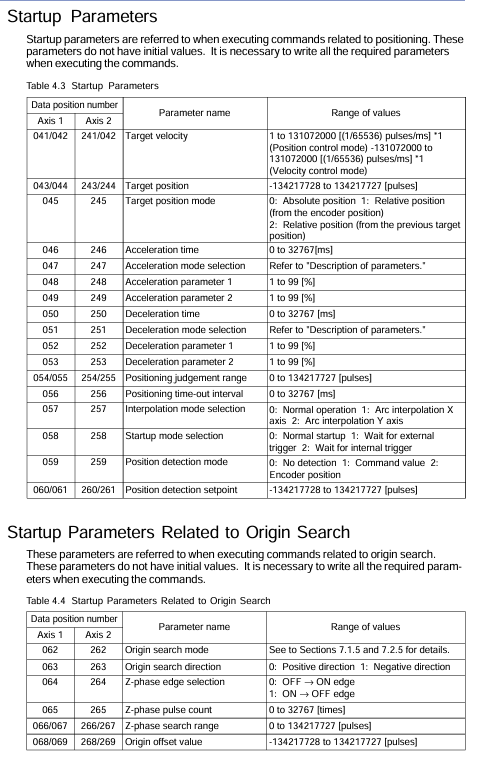
Startup parameters: including target speed, target position, target position mode (absolute/relative), acceleration and deceleration time/mode/parameters, positioning judgment range, timeout time, interpolation mode, startup mode, position detection mode/set value, etc. There is no initial value, which needs to be written before instruction execution.
Origin search parameters: including origin search mode (contact detection action), search direction, Z-phase edge selection, Z-phase pulse count, Z-phase search range, origin offset value, no initial value.
Extended instruction parameters: including extended instruction type (servo ON/OFF, brake ON/OFF, driver reset, etc.), static deviation adjustment, manual pulse generator proportional value, without initial value.
Arc interpolation parameters: including center position, radius, starting angle, angle movement, angle target velocity, acceleration and deceleration time, target position, correction pulse range, without initial values.
3. Example of parameter settings
Taking "motor rated speed 3000rpm, rated voltage 6V, encoder 8192 pulses/rev (4x), ball screw pitch 5mm/rev, operating range -500~1000mm" as an example, the key inlet parameters are calculated as follows:
Positive limit value: 1000mm ÷ 5mm/rev x 8192 pulses/rev=1638400 pulses;
Negative limit value: -500mm ÷ 5mm/rev x 8192 pulses/rev=-819200 pulses;
Speed limit value: (100mm/s ÷ 5mm/rev × 8192 pulses/rev) ÷ 1000 × 65536=10737418 (1/65536) pulses/ms;
Speed/voltage ratio: (3000rpm × 8192 pulses/rev ÷ 60s/min) ÷ 6V=68267 pps/V.
Status and I/O Relay
1. Status monitoring
The module status needs to be read through the CPU module, and the core status items are as follows (2-digit data needs to be read as "low word+high word", some of which are fixed-point data):
Status Name Axis 1 Data Position Axis 2 Data Position Description
Error status 101 301: Store error code when an error occurs, meaningless when there are no errors
Contact input status 103 303 stores the external contact input (including emergency stop) status, with 1 bit corresponding to 1 input and polarity defined by parameters
The current status of the instruction position is the path position generated by module 104/105 304/305, which is not the actual position of the motor and is measured in unit pulses
Encoder Position Current Status 108/109 308/309 Encoder Feedback Motor Actual Position, Unit Pulse
Target position status 112/113 312/313: The target position of the positioning operation (calculated according to the target position mode)
Extended state 114 314 stores operational states (acceleration/constant speed/deceleration, mode waiting, control mode, etc.), parsed bit by bit
Remaining deceleration time 115 315 Remaining deceleration time from positioning to target position, 0=path generation stop, -1=acceleration/uniform speed
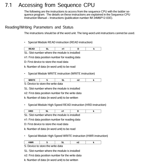
2. I/O relay (interface CPU module)
Output relays (32 per axis, F3NC51-0N's 2-axis relay is invalid): The core includes start operation instructions (Y Ⅲ 33/49), extension instructions (Y Ⅲ 34/50), deceleration stop requests (Y Ⅲ 35/51), immediate stop requests (Y Ⅲ 36/52), origin search start (Y Ⅲ 37/53), etc., where III is the FA-M3 slot number where the module is located.
Input relays (32 per axis, F3NC51-0N 2-axis relays are meaningless): The core includes confirmation of start operation instructions (X Ⅲ 01/17), confirmation of extension instructions (X Ⅲ 02/18), confirmation of deceleration stop (X Ⅲ 03/19), end of origin search (X Ⅲ 05/21), end of positioning (X Ⅲ 14/30), error notification (X Ⅲ 12/28), etc.
- YOKOGAWA
- Reliance
- ADVANCED
- SEW
- ProSoft
- WATLOW
- Kongsberg
- FANUC
- VSD
- DCS
- PLC
- man-machine
- Covid-19
- Energy and Gender
- Energy Access
- Renewable Integration
- Energy Subsidies
- Energy and Water
- Net zero emission
- Energy Security
- Critical Minerals
- A-B
- petroleum
- Mine scale
- Sewage treatment
- cement
- architecture
- Industrial information
- New energy
- Automobile market
- electricity
- Construction site
- HIMA
- ABB
- Rockwell
- Schneider Modicon
- Siemens
- xYCOM
- Yaskawa
- Woodward
- BOSCH Rexroth
- MOOG
- General Electric
- American NI
- Rolls-Royce
- CTI
- Honeywell
- EMERSON
- MAN
- GE
- TRICONEX
- Control Wave
- ALSTOM
- AMAT
- STUDER
- KONGSBERG
- MOTOROLA
- DANAHER MOTION
- Bentley
- Galil
- EATON
- MOLEX
- Triconex
- DEIF
- B&W
- ZYGO
- Aerotech
- DANFOSS
- KOLLMORGEN
- Beijer
- Endress+Hauser
- schneider
- Foxboro
- KB
- REXROTH
- YAMAHA
- Johnson
- Westinghouse
- WAGO
- TOSHIBA
- TEKTRONIX
- BENDER
- BMCM
- SMC
- HITACHI
- HIRSCHMANN
- XP POWER
- Baldor
- Meggitt
- SHINKAWA
- Other Brands
- UniOP
- KUKA
- IBA
- Beckhoff
- ADLINK
-
Beckhoff CX1100-0910 - Power Supply Module
-
Beckhoff C5210-0010 - Communication Module C5210
-
BECKHOFF KL1352 - Bus Terminal SET OF 2 FREE FAST SHIP
-
Beckhoff EL3058 - 8 x analog input single ended 4...20mA 85惟 shunt 12bit
-
Beckoff CX1100-0920 - UPS Module 24VDC (US SELLER) * *
-
BECKHOFF C6920-0000 - C69200000 PLC Moudule
-
Beckhoff CX5120-0115 - CPU controller module CX5120-0115
-
Unknown 15F5C1E-Y50A - Of Frequency Converters
-
Beckhoff AX5118-0000-0200 - Servo Drive HTP0
-
BECKHOFF AX5106-0000-0200 - Servo Drive
-
Beckhoff CX5240-0175 - Module (free) #U2327D YG
-
Beckhoff CP6607-0001-0000 - Compact PC Panel Economy Installation Operator 5,7 "
-
Beckhoff EP3744-0041 - 2022 EP37440041 Module
-
Beckhoff CP6209-0001-0020 - 6.5" PC Touch Screen Control Panel 24VDC
-
Beckhoff CX9020-0111 - /U900 +8x+2xEL3121+1x EL9410+3xEL1008+1x EL2008 Set
-
Beckhoff C6525-1030-0050 - Industrial PC
-
Beckoff CX1100-0920 - UPS Module 24VDC (US SELLER)
-
Beckhoff CX5010-0120 - CX5010 Processor Intel Atom Z510 B24
-
Siemens 6FC5203-0AF04-1BA1 - Operation Panel
-
Beckhoff CX5230-0175 - / 000029724 Embedded PC / Industrial PC on Rail
-
Beckhoff CP3916-0000 - industrielles Anzeige- und Bedienterminal
-
BECKHOFF CX1500-M310 - CX1000-N000 CX1000-0011 CX1000-C00L CX1100-0002 PLC Module
-
Beckhoff EL1872 - 16-channel digital input terminal
-
BECKHOFF EP2318-0001 - module
-
Beckhoff CX9020-0110 - Basic CPU Module
-
Beckhoff EL2564 - EtherCAT Terminal, 4-channel LED output, 5鈥?8VDC, 4A, RGBW
-
Beckhoff CX5130-0155 - /000105637 Automation Embedded PC
-
B&R 400 - Power Control Panel Rev D0 24 VDC
-
Beckhoff CX2020-0155 - module
-
Beckhoff CX9020-0115 - PLC Module
-
BECKHOFF EL6695 - PLC EL 6695
-
BECKHOFF EL7047 - PLC Modules
-
Beckhoff CX1000-0012 - Control HW 2.2 + CX1500-M310 + CX1000-C00L + CX1100-0002+
-
Beckhoff C6920-1039-0030 - control cabinet industrial PC CPU Celeron 1.90 GHz, 2 cores
-
BECKHOFF CX1100-0910 - PLC Module#
-
Beckhoff IL2301-B318-0000 - Coupler Box 4 Channel Digital Input |
-
Beckhoff CX7080 - Module
-
Beckhoff C6930-0060 - Industrial PC
-
Beckhoff CP7902-1060-0000 - Touchscreen 15 " CP7902
-
beckhoff CX9020-0111 - Controller module or UPS
-
Beckhoff CX8091 - PLC Module CX8091
-
Beckhoff C6640-1008-0030 - Control Cabinet Industrial PC
-
BECKHOFF CX1100-0920 - module
-
Beckhoff C9900-M921 - see pictures
-
BECKHOFF CP6829-0001-0000 - Touch Panel
-
BECKHOFF C6930-0060 - Industrial Computer
-
BECKHOFF CX8050 - PLC module
-
Beckhoff CP6202-0021-0020 - Touch Screen #
-
BECKHOFF AM3031-0C20-0000 - SERVO MOTOR
-
Unknown BCH1302N11A1C - Servo motor
-
Beckhoff EL2502 - 2-channel pulse width output terminal
-
Beckhoff EL6731 - Profibus Master / *Rev: 0025
-
Beckhoff CP3918-0010 - Control Panel
-
BECKHOFF CP2915-0010 - [24 MONTH WARRANTY] Control Panel
-
Beckhoff AX5203-0000-0202 - Servo Drive
-
Schneider TSXDSY64T2K - PLC OUTPUT MODULE
-
Beckhoff EP4174-0002 - Module-
-
Beckhoff IL2302-B318-0000 - Profibus Box
-
Beckhoff CP6709-0001-0000 - Touchpanel
-
BECKHOFF CX2030-0123 - Controller
-
Beckhoff CX9020-0111 - Processor Module
-
Beckhoff CX1020-0000 - CX Basic CPU Module
-
Beckhoff AX2003-AS - Servo Drive HTP0
-
Beckhoff C6240-1052-0040 - 4-086-06-3073 Industrial Computer CB1052-0003
-
Beckhoff EL1918 - 8 xTwinSAFE Input
-
Beckhoff AM8072-0R20-0000 - Servomotor
-
BECKHOFF AM8021-1B21-0000 - servo motor #T882 YS
-
Beckhoff EL6224 - 4 X Terminal IO-LINK
-
Beckhoff CX5140-0135 - embedded PC with Intel Atom processor 4 GB HW 3.6
-
Beckhoff CP7201-1000-0000 - Panel PC #
-
Beckhoff CX5130-0121 - Embedded-PC 4GB CPU Module HW 2.5 Industrial PC
-
Beckhoff AM8022-0D41-1002 - Servomotor
-
BECKHOFF CX2030-0130 - Module
-
BECKHOFF EL1872 - 16-channel digital input terminal
-
Unknown GXMMW.A203P33 - 1pc encoder
-
Beckhoff EL6631-0000 - EtherCAT Terminal 2-Port EL 6631
-
BECKHOFF C6925-0030 - Industrial Computer
-
Beckhoff CX8190 - A Module
-
BECKHOFF CX2040-0135 - CX2040-0135/000000927 CPU BASE MODULE i7 2715QE 2.1GHz --
-
BECKHOFF KL6023-0000 - Wireless adapter
-
Saia Burgess PCD7.F700 - PCD7F700 Communication Module
-
Beckhoff CX5130-0112 - CPU Module
-
BECKHOFF CX1020-N010 - CX1020-N000 CX1020-0111 CX1100-0004 EL2008 EL3064 EL4004
-
Beckhoff EP1819-0021 - A Module
-
Beckhoff CX2030-0120 - / 4gb with CX2100 0004
-
B&R X20-XC-0292 - Automation Powerlink Ethernet Bus Controller Module
-
Beckhoff BK3110 - One PLC Module
-
BECKHOFF KL3222 - PLC Module
-
BECKHOFF CX1500-M310 - CX1000-N000 CX1000-0011 CX1000-C00L CX1100-0002 PLC MODULE
-
Beckhoff CP3918-0010 - Control Panel
-
Beckhoff CX2030-0100-1002 - /4GB + CX2100 + CX2550 + CX2500-0060 + SSD
-
Beckhoff EP1816-0008 - PLC Module
-
Beckhoff CX5130-0112 - Module
-
Beckhoff Cx1500-m750 - CPU Hw: 1.4
-
BECKHOFF AX5112-0000-0200 - AX511200000200 Servo Driver
-
Beckhoff EL3751 - EtherCAT Terminal 1 Channel Analog Input Multifunction 24 Bit
-
Beckhoff CX1100-0002 - Power Supply Module
-
Beckhoff CP3916-1016-0010 - Control Panel
-
BECKHOFF CX9001-1101 - #NAME?
-
Beckhoff EP3174-0002 - EtherCAT Box Module
-
Beckhoff C6030-0070 - servo drive
-
Beckhoff CX2020-0120 - /4GB CPU, CX2100-0904, 3x EL6900, EL1904, 16GB Memory
-
BECKHOFF C6110 - BOX-PC 113608
-
BECKHOFF EK1914 - module #P
-
Beckhoff C6140 - Ipox IP-4GVI63 + CH7009A_DVI_TV + SIEMENS A5E00369843 + WD800AAJB
-
Beckhoff CX5020-0111 - controller Good quality
-
BECKHOFF C6015-0010 - / 6559380 ULTRA-COMPACT INDUSTRIAL PC ()
-
Beckhoff AX5203-0000-0200 - PLC module
-
Beckhoff EL2872 - 16-channel digital output terminal
-
BECKHOFF C3640-0000 - Panel Industrial PC 100/240VAC 128MB E0122L
-
Beckhoff CX8031 - Module
-
Beckhoff CX5020-0120-1002 - PLC module#
-
Beckhoff C6140 - M845B + SIEMENS A5E00369843 + C9900_A159_1 + AUTOMATA CAN PCI 1N
-
BECKHOFF AX5112-0000-0200 - Servo Drive*ie
-
B&R ECPA42-01 - Analog Output Module 4-Channel, +/- 10V Output Signal, 20mA Max
-
Beckhoff EL6631-0010 - PLC Module
-
BECKHOFF C6930-0070 - CONTROL CABINET INDUSTRIAL PC
-
BECKHOFF AX5112-0000-0200 - AX511200000200 Servo Driver
-
BECKHOFF EK9000 - Programmable Logic Controller Module EK9000 EK9000
-
BECKHOFF C6920-1028-0000 - Industrial computer
-
Beckhoff CX2030-0120 - controller Module
-
Beckhoff BX8000-0000 - Bus Terminal Controller HW 4.4
-
B&R 3NC154.60-2 - Positioning Module#
-
BECKHOFF CX1020-0122 - PLC module
-
Beckhoff AM3032-0D40-0000 - Servo Motor
-
BECKHOFF CX5020-0111 - CPU Module CX5020-0111
-
Beckhoff CB1051 - G5 Motherboard
-
BECKHOFF KL2641 - 1-channel relay output terminal

K-JIANG

Add: Jimei North Road, Jimei District, Xiamen, Fujian, China
Tell:+86-15305925923