
K-WANG


Foxboro ™ DCS Field Device Controller 280(FDC280)
Foxboro ™ DCS Field Device Controller 280(FDC280)
Product Overview and Core Positioning
FDC280 is a distributed and optional fault-tolerant on-site installation controller, with the core function of implementing Foxboro ™ The integration of DCS and field devices does not require additional fieldbus modules (FBM), and it also undertakes process control and alarm tasks. It is mainly positioned as the "field device integration center", which is different from the same type of FCP280 (which does not support PIO bus and focuses on Ethernet/serial protocol integration).
1. Core functions
Device integration: Directly interface with Ethernet/serial field devices that support multiple protocols, collect device data for display, historical storage, and execute control tasks.
Control capability: Built in adjustment control, logic control, timing control, sequence control functions, supporting alarm detection and notification.
Hardware architecture: Adopting dual core ARM ® SOC processor with clear dual core division of labor:
Core 1 (Control Core): Run control software and DCS control network communication software, supporting fault-tolerant operations.
Core 2 (I/O core): Run device integration software, independently handle on-site device connections and status diagnostics.
Basic requirements: A host workstation with Foxboro DCS Control Core Services v9.3 or higher must be installed, and connected to the control network via 100Mbps fiber/copper Ethernet. It must have obtained ISASecure EDSA Level 1 security certification.
2. Key difference: FDC280 vs FCP280
Comparison item FDC280 FCP280
Core positioning on-site equipment integration (Ethernet/serial port) universal process control
PIO bus support not supported
Core advantage: No FBM required, directly integrated with field devices compatible with traditional PIO bus devices
Network configuration plan
FDC280 supports both Ethernet and serial network configurations, divided into two modes: "simplex" and "fault tolerant", to meet the redundancy requirements of different field devices.
1. Ethernet network configuration
Support direct connection to Ethernet field devices or connection to serial devices through a "protocol specific gateway" (to achieve Ethernet serial bridging), with three core solutions:
Configuration Type Applicable Scenarios Key Features
Simplex, a single FDC280 module for scenarios with low reliability requirements, does not require redundant connections and saves wiring costs
Fault tolerant - Independent network with high reliability requirements, on-site equipment requires independent redundant network dual FDC280 modules (left/right), connected to two independent Ethernet networks provided by customers, with module IP addresses that can be the same or unique
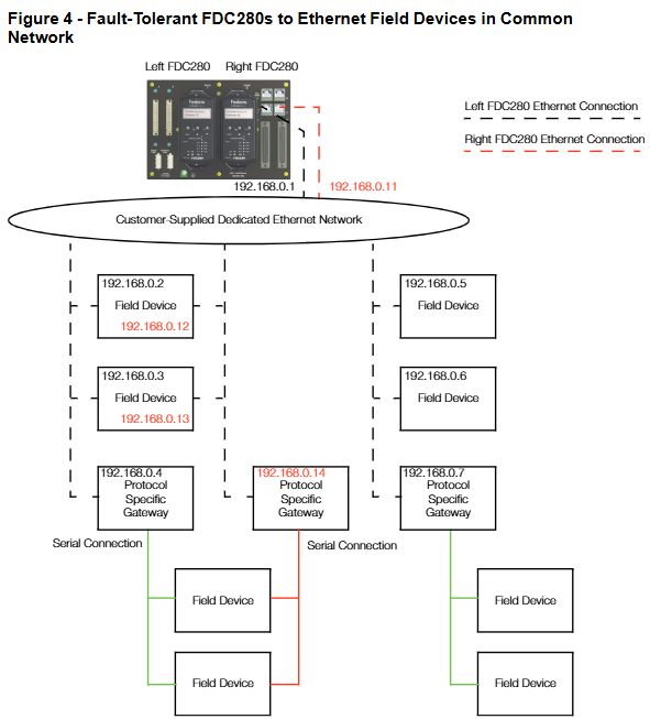
Fault tolerant - Shared network field devices without independent redundancy requirements (such as single port devices). Dual FDC280 modules share one Ethernet network, supporting single port device access and reducing network complexity
Note: It is recommended to use a management switch for easy maintenance and troubleshooting; The device can also be directly connected to the FDC280 motherboard without the need for a switch.
2. Serial port network configuration
Each module of FDC280 contains 4 independently configurable serial ports (supporting RS232/RS422/RS485), with a maximum support of 128 serial field devices (up to 32 devices per RS485 port). The core solution is divided into 2 types:
Non fault-tolerant (Simplex): A single FDC280 can be connected to a single port serial device through a "Terminal Component (TA)", supporting RS485 multi station connection without a modem and RS232/RS422 direct connection.
Fault tolerant type: Dual FDC280 modules are connected to devices through TA and adapted to different port devices:
Dual port device: The left/right module connects the two ports of the device separately to achieve redundant communication.
Single port device: RS232 needs to be connected to two TAs through a Y-shaped cable; RS485/422 can be directly connected through a dual module TA sharing connection.
Core features and performance parameters
1. Key functional characteristics
Specific description of characteristic categories
The device and I/O capacity support a maximum of 256 field devices, 8000 soft I/O points, and 8252 total functional blocks (including Station blocks, ECB components, etc.). Please refer to the FDC280 sizing tool (B0700GS) to calculate the load
The protocol supports 6 core protocols, some of which support concurrent multi instance/multi version (see table below for details)
The diagnostic capability has a built-in "diagnostic driver" that can capture real-time communication messages with the device and send them to the workstation diagnostic application without physical interruption
Fault tolerance mechanism dual module "marriage" operation, Control Network communication requires dual module messages to be matched bit by bit before sending; Core 1 supports primary/backup switching, while Core 2 supports redundancy state comparison and role handover
In self hosted mode, the control database checkpoint file is stored in flash memory, and the host can autonomously start and execute control policies when offline
Software updates distinguish between "Major updates (new features, no online upgrade support)" and "Minor updates (only module switching, no process interruption)"
Environmental adaptability die-casting aluminum shell, no need for ventilation, supports Class G3 harsh environment (ISA S71.04 standard), CE certification for on-site installation
Time synchronization supports GPS satellite UTC time (external) or DCS internal TimeKeeper synchronization (internal), with data timestamp accuracy of 10 times/second (minimum scanning interval of 100ms)
2. Support protocols and concurrency capabilities
Protocol name, part number, multiple protocols, concurrent support, same protocol, multiple instances support
Modbus TCP Client K0177AH Yes Yes
Modbus RTU&ASCII Client K0177CV Yes
Triconex ™ TSAA Client K0177DE is
OPC UA Client K0177EC (single instance only)
Is EtherNet/IP Scanner Driver K0177EP
PROFINET IO Controller K0177FU No No (single instance only)
3. Functional specification parameters
Specific numerical values for parameter categories
The maximum execution speed of functional blocks with a processor performance of 16000 blocks per second, and the minimum block processing cycle (BPC) of 100ms
The maximum capacity of a single sequence block is 32KB
IPC connects 200 data source points (providing external data), 30 sink points (receiving external data), and 1 dedicated internal point
OM (Object Manager) can scan a database with a maximum capacity of 28000 points (18000 points when BPC ≥ 200ms, 7500 points when BPC=100ms); The maximum convergence point is 11250 points
Configurable block period of 0.1/0.2/0.5/0.6/1/2/5/6/10/30 seconds, 1/10/60 minutes
Fault tolerant module pairing time is less than 0.5 seconds
Hardware and environmental specifications
1. Core hardware components and parameters
The FDC280 hardware includes four categories: "module", "motherboard", "network adapter", and "terminal component". The key parameters are as follows:
Component type, model/part number, key specifications
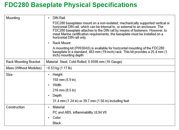
FDC280 module RH101FQ size: height 105/116mm (including installation ears) x width 51.8mm x depth 147mm; single module weight 0.8kg
The base plate RH101KF (2 bits) supports 1 non fault tolerant module or 2 fault tolerant modules, including 2 10/100Mbps/1Gbps copper cable Ethernet RJ45 interfaces, 2 37 pin D-type serial port interfaces, and 2 time synchronization interfaces
Network adapter fiber optic: RH924WA (Rev. E+); Copper cable: RH924UQ (Rev. D+) takes power from the base plate, fiber supports multimode 62.5/125 μ m cable (maximum 2km), copper cable supports Cat5 (maximum 100m)
Serial terminal component ring terminal post: P0926PA; Tightening screws: RH926GH weighs 363g and 272g respectively, and needs to be paired with Type 5 terminal cables (such as RH100HV-1m and RH100HZ-5m)
2. Power and environmental requirements
Category specifications
Power requirement input voltage: 24VDC (redundant,+5%/-10%); The maximum power consumption of a single module is 8.5W
Working temperature -20~60 ℃ (-4~140 ℉)
Storage temperature -40~70 ℃ (-40~158 ℉)
Relative humidity 5%~95% (no condensation)
Altitude operation: up to 3000m; storage: -300~12000m
Anti pollution level Class G3 (ISA S71.04), supports 10-year mixed gas exposure testing (EIA 364-65A Class III), module with conformal coating (conformal coating: protective coating)
Vibration resistance 0.5g (5~500Hz)
3. Compliance certification
Electromagnetic Compatibility (EMC): Compliant with Directive 2014/30/EU, EN 61326-1 Class A (Emission and Industrial Immunity).
Product safety: UL/UL-C certification (applicable to Class I, Groups A-D, Zone 2), EU Low Voltage Directive (2014/35/EU), ATEX Directive (2014/34/EU, DEMKO Ex nA IIC T4 Gc, applicable to Zone 2).
Environmental compliance: Compliant with the EU RoHS Directive (2011/65/EU and revised versions 2015/863, 2017/2102).
California Proposition 65: Products containing lead and lead compounds may cause cancer or reproductive harm, details can be found at www.P65Warning.ca.gov.
Fault tolerance mechanism and reliability design
The "fault-tolerant" core of FDC280 consists of dual module redundancy, independent diagnosis, and seamless switching, covering the control network, CPU, and I/O levels to ensure uninterrupted processes
1. Three layer fault-tolerant/redundant design
Level fault tolerance/redundancy mechanism switching logic
The dual modules of the control network are connected through the backplane and share control network access (dual switches). Communication messages need to be matched bit by bit by the dual modules before being sent. When a fault is detected, the non faulty module takes over control without process interruption
Core 1 (control core) primary/backup mode, real-time synchronization status. When the primary core fails, the backup core immediately switches to primary dynamic mode
Core 2 (I/O core) independently diagnoses the connection status of dual core devices. When the main core fails and the backup core device is better connected compared to the backup core status, the main core resets and hands over the role
The main module on the I/O side is responsible for reading and writing I/O points, while the backup module monitors device connections through "heartbeat commands" and synchronizes I/O values in real-time. When the main module loses connection, the backup module seamlessly takes over without any process fluctuations
2. Maintain convenience
Hot plug support: Replacing the FDC280 module does not require disconnecting the backplane power supply, and does not affect the field I/O signal of another module.
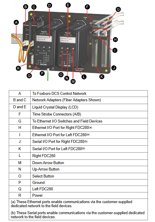
Status visualization: The front of the module includes an LCD display screen (displaying module identification, role, hardware version, network status) and LED indicator lights (running status, Ethernet connection status), supporting the configuration of "letterbug" through panel buttons.
- YOKOGAWA
- Reliance
- ADVANCED
- SEW
- ProSoft
- WATLOW
- Kongsberg
- FANUC
- VSD
- DCS
- PLC
- man-machine
- Covid-19
- Energy and Gender
- Energy Access
- Renewable Integration
- Energy Subsidies
- Energy and Water
- Net zero emission
- Energy Security
- Critical Minerals
- A-B
- petroleum
- Mine scale
- Sewage treatment
- cement
- architecture
- Industrial information
- New energy
- Automobile market
- electricity
- Construction site
- HIMA
- ABB
- Rockwell
- Schneider Modicon
- Siemens
- xYCOM
- Yaskawa
- Woodward
- BOSCH Rexroth
- MOOG
- General Electric
- American NI
- Rolls-Royce
- CTI
- Honeywell
- EMERSON
- MAN
- GE
- TRICONEX
- Control Wave
- ALSTOM
- AMAT
- STUDER
- KONGSBERG
- MOTOROLA
- DANAHER MOTION
- Bentley
- Galil
- EATON
- MOLEX
- Triconex
- DEIF
- B&W
- ZYGO
- Aerotech
- DANFOSS
- KOLLMORGEN
- Beijer
- Endress+Hauser
- schneider
- Foxboro
- KB
- REXROTH
- YAMAHA
- Johnson
- Westinghouse
- WAGO
- TOSHIBA
- TEKTRONIX
- BENDER
- BMCM
- SMC
- HITACHI
- HIRSCHMANN
- XP POWER
- Baldor
- Meggitt
- SHINKAWA
- Other Brands
- UniOP
- KUKA
- IBA
- Beckhoff
- ADLINK
-
ADLINK HPCI-14S12U - Industrial Control Backplane 12PCI Backplane PCI-14S Passive Backplane
-
ADLINK PCIe-GIE74C - image acquisition card 4-CH GigE Vision PoE+ Frame Grabber
-
ADLINK PCI-8164 - control card 4-Axis Advanced Motion Controller Board
-
ADLINK PCIe-U304 - 4 Port USB3 PCIe Frame Grabbers USB Screw Hole Card
-
ADLINK PCI-9112 - Multi-Function Data Acquisition Card DAQ Card
-
ADLINK PCI-7432 - 51-12013-0A50 4-CH Isolated Numérique I/O PCI Cartes Digital I/O Card
-
ADLINK PCA-6106P3-0C1 REV.C1 - backplane 6-Slot Passive Backplane Board
-
ADLINK PCI-7224 - 24-CH Opto-Isolated Digital I/O PCI Board
-
ADLINK CPCI-7433R(G) - Digital Input Board Rear I/O CompactPCI Card
-
ADLINK EBP-13E4 - 51-46703-0A30 Industrial PC Backplane Passive Backplane
-
ADLINK PCIE-HDV62 - Image acquisition card High Definition Video Frame Grabber
-
ADLINK EBP-13E4 - 51-46703-0A30 Industrial Backplane Board Passive Backplane
-
ADLINK 90111-B1 / CPCI-6770 - PCB CPU MODULE CompactPCI Single Board Computer
-
ADLINK PCI-7248 - DATA ACQUISITION PCI CARD 48-CH Parallel Digital I/O Board
-
ADLINK PCI-7230 - 51-12003-0a50 board PCI7230 32-CH Isolated Digital I/O Card
-
ADLINK PCI2A000CB - 51-20000-0B30 Multi-Function DAQ Card Baseboard
-
ADLINK PCI-8134-005 - 4-Axis Motion Controller Card
-
ADLINK PCI-7224 - 24-CH Opto-Isolated Digital I/O PCI Card
-
ADLINK PCI-7434 - 64-CH Isolated Digital Output Card
-
ADLINK PCI-8132 - motion control card 2-Axis Servo & Stepper Controller
-
ADLINK PCI-8134 - Motion Controller PCI Card 4-Axis Controller Board
-
ADLINK PCI-8164 - Motion Control Card 51-12406-0A40 4-Axis Controller
-
ADLINK 51-12001-0C20 - Circuit Board Data Acquisition Interface Module Hardware
-
ADLINK NuPR0-840 - industrial control motherboard Full-Size PICMG CPU Board
-
ADLINK PCI-7444 - 51-12023-0A10 card 128-CH Isolated Digital Output Board
-
ADLINK PCI-1612B - data acquisition card 4-Port RS-232/422/485 Serial Communication Card
-
ADLINK PCI-6208V 009 - 8/16-CH 16-Bit Analog Output Cards PCB-I-E-482=6BX3
-
ADLINK NUPRO-935A/LV - industrial control motherboard Full-Size PICMG SBC Board
-
ADLINK PCI-9114DG - Multi-Function DAQ Card Data Acquisition PCI Card
-
ADLINK ACL-7130 - Data acquisition card Isolated Digital I/O Board
-
ADLINK cPCI-6626 - 6U CompactPCI 2.0 Blades i7-2710QE PCB-I-E-2570=9N41
-
ADLINK MXC-6322D(G) - Industrial Fanless Computer
-
ADLINK cPCI-8168-004 - CompactPci NulPC Motion Control Board 51-36402-0A3
-
ADLINK CPCI-7300[G] - COMPACTPCI Digital I/O Card Data Acquisition
-
ADLINK CPCI-6626/2710/M4G - COMPACTPCI COMPUTER BOARD
-
ADLINK cPCI-8168-009 - cPCI NulPC Motion Control Board
-
ADLINK cPCI-6626/2710/M4G - VME CPU Board Computer Board
-
ADLINK CPCI-R6200(G)-0040 - COMPACTPCI CONTROL BOARD
-
ADLINK CPCI-3840/PM18/M1G(G)-3650 - COMPACTPCI CPU Module Single Board Computer
-
ADLINK cPCI-7248 - 48-CH Opto-22 Compatible Digital I/O Module
-
ADLINK DLAP-211-JNX - NVIDIA Jetson Xavier NX Edge AI Inference Platform
-
ADLINK cPCI-3544 - Series 4-Port RS-422/485 Isolated Serial Communications Card
-
ADLINK CM1-86DX3 - PC/104 SBC Stanley Vortex86DX3 CPU 2GB Ram
-
ADLINK DLAP-211-JNX - NVIDIA Jetson Xavier NX Edge AI Inference Platform
-
ADLINK cPCI-3544 - Series 4-Port RS-422/485 Isolated Serial Communications Card
-
ADLINK CM1-86DX3 - PC/104 SBC Stanley Vortex86DX3 CPU 2GB Ram
-
ADLINK PCI-7433 - switch value acquisition card Isolated Digital Input Card
-
ADLINK PCI-9112 - 51-12252-0D20 Multi-Function Data Acquisition Card
-
ADLINK NUPRO-A301 REV:1.4 - industrial control motherboard PICMG Full-Size SBC
-
ADLINK 51-18502-0A10 - Frame Grabber Image Acquisition Interface Card
-
ADLINK PCI-7296 - 51-12009-0A50 PCB-I-E-925=6DX1 96-CH Parallel Digital I/O Board
-
ADLINK PCI-8132 GP A2 - Motion Control Card 2-Axis Servo & Stepper Controller
-
ADLINK PCI-7442 - switch quantity card data acquisition card 64-CH Isolated Card
-
ADLINK HPX-13S4 - baseboard PICMG 1.3 Passive Backplane Chassis Baseplate
-
ADLINK NuPRO-590 / NTC-567-ZM-F36 - Single Board Computer PCB-I-E-1853=9L21 Half-Size SBC
-
ADLINK PCIe-8332 - 16-axis plate Motion Control Hardware Card
-
ADLINK NuPRO-775 REV.B1 - motherboard Pentium 4 Full-Size PICMG SBC
-
ADLINK PXI-3920 - Embedded Controller 3U PXI cPCI System Intelligence Board
-
ADLINK PCI-8134 - driver card motion control card 4-Axis Controller Board
-
ADLINK HSL-DI32-M-N-011 / HSL-TB32-M-DIN - Digital Input & Base Module PLC Distributed I/O System
-
ADLINK PCI-6216V-206 / PCI-208V 009 - 16 CH 16bit analog output card
-
ADLINK NuPro-E330 - 51-41805-0A20 PCB Single Board Computer Host Board
-
ADLINK PCI-1622C - Card 8-Port RS-232/422/485 PCI Serial Communication Board
-
ADLINK PCIe-7432 - 51-18402-0A10 Carte PCIe Avec Plage D'Entrée Élevée Isolated DIO Card
-
ADLINK PCI-7250 - PCI Acquisition Card 8-CH Relay Output Isolated DI Card
-
ADLINK PCI-7230 - 32-CH Isolated Digital I/O Card
-
ADLINK PCI-8164 - PCB 4-Axis Motion Controller Card
-
ADLINK PCI-7854 - Collection card High-Speed Link Distributed Motion Controller
-
ADLINK NuPRO-935A/LV - industrial control computer motherboard Full-Size PICMG SBC
-
ADLINK IMB-M40H - motherboard IH61-AA4 1155 LGA1155 Micro-ATX Mainboard
-
ADLINK PCI-7248 - Linhua 51-12006-0A40 48-CH Parallel Digital I/O Card
-
ADLINK HPCI-14S12U - Linhua industrial computer baseboard Passive Backplane
-
ADLINK PCI-8132 Rev.A2 - 2-Axis Servo & Stepper Motion Controller Card
-
ADLINK ACL-8111 - ISA card Multi-Function DAQ Card
-
ADLINK ACL-8111 - ISA card Multi-Function Data Acquisition Board
-
ADLINK PCI-7200 REV.A3 - Digital I/O card 12MB/s High-Speed Parallel Digital I/O
-
ADLINK PCI-7296 REV.A3 - 96-CH High-Density Opto-Isolated DIO Card
-
ADLINK PCI-7434 - 64-CH Isolated Digital Output Card
-
ADLINK M-342 - atx motherboard Industrial PC Mainboard
-
ADLINK NuPRO-935ADV (A) 1.9 - CPU Board Intel Core 2 Quad CPU Q9500 2.83GHz PICMG Board
-
ADLINK NUPRO-935A/DV - motherboard dual network port 51-41802-0A10 CPU Board
-
ADLINK PCI-RTV24 - image capture card Analog Video Frame Grabber Board
-
ADLINK HPX-13S4 - device baseboard PICMG 1.3 Passive Backplane Chassis Baseplate
-
ADLINK PCI-8134A - control card 4-Axis Motion Controller Card
-
ADLINK ACL-7130 REV. B2 - industrial control capture card Isolated Digital I/O Board
-
ADLINK EBP-13E2 - Industrial Backplane Board Passive Backplane Baseboard
-
ADLINK NuPRO-935ADV (A) 1.9 - CPU Board Intel Core 2 Quad CPU Q9500 2.83GHz PICMG SBC
-
ADLINK PCI-8134A - motion control card 4-Axis Pulse-Train Controller Card
-
ADLINK PCI-9112 REV A.1 - Multi Function DA&C Board Data Acquisition Card
-
ADLINK 51-12001-0C20 - Circuit Board Multi-Function Data Acquisition Hardware
-
ADLINK PCI-7300A - 80-CH High-Speed Digital I/O Card
-
ADLINK PCI-7230 - 16-CH Isolated Digital Input Output Card
-
ADLINK DIN-814-GP - motion control module Interface Terminal Block
-
ADLINK NUPRO-A40H - 51-41807-1A20 Industrial Control Motherboard LGA1155
-
ADLINK PCI-7433 rev A2 - Isolated Digital Input Card
-
ADLINK NuPRO-780 - Pentium III 800 512 MB SBC NuPRO780 51-41309-0B2 Single Board Computer
-
ADLINK PCI-7853 / PCI-7854 - Acquisition card High-Speed Link Control Card
-
ADLINK NUPRO-852 / NUPRO-852LV - Industrial motherboard Full-Size PICMG CPU Board
-
ADLINK NuPRO-842LV/P - 51-41360-0B30 Industrial Motherboard Half-Size PICMG SBC
-
ADLINK PCI-FIW64 - 4/2 Channel IEEE1394B Image Capture Card Frame Grabber
-
ADLINK PCI-7851 Rev A1.1 - HSL system card High-Speed Link Master Controller
-
ADLINK PCI-7230 - 51-12003-0A50 card 32-CH Isolated Digital I/O Card
-
ADLINK NuPRO-841REV:1.0 - Industrial CPU Board Mainboard
-
ADLINK NuPRO-841 REV:1.0 - motherboard Industrial Control PC Mainboard
-
ADLINK PCI-8256 - 8-Axis Advanced Motion Control PCI Board
-
ADLINK PCI-6S / PCI6S - Backplane 6-Slot Passive Backplane Board
-
ADLINK PCI-7234 REV B3 - 32-CH Isolated Digital Output PCI Card
-
ADLINK PCI-8213 - HannStar MV-4 51-45003-0b4 Board
-
ADLINK PCI-7233 - 51-12004-0a20 board PCI7233 32-CH Isolated Digital Input Card
-
ADLINK PCI-7851 - 006 51-24003-0B20 High-Speed Link Master Motion Control Card
-
ADLINK PCI-7432 - 64-CH Isolated Digital I/O PCI Cards
-
ADLINK LPCI-3488 - Card Low Profile IEEE-488 GPIB Interface Card
-
ADLINK HPCI14S REV.B1 - industrial control computer base plate Passive Backplane
-
ADLINK NEON-1020 - Industrial camera Smart Camera Vision System
-
ADLINK PCI-7432 - Isolated Digital I/O PCI Card 64-CH
-
ADLINK Pcm-7250+ - 8-Ch Relay Outputs & 8-Ch Isolated DI Module PC/104
-
ADLINK CPCI-7841 - DUAL-PORT ISOLATED CAN INTERFACE CARD CompactPCI
-
ADLINK PCI-3488 / PCI-GPIB - PCI IEEE-488 GPIB Interface Card
-
ADLINK PCI-1711U - Card Multi-Function Data Acquisition Board
-
ADLINK NUPRO-A301 - REV:1.1 1.2 1.4 PICMG Full-Size Single Board Computer
-
Adlink DIN-50S-01 - PLOTECH 51-14024-0A40 50-pin Wiring Terminal Board
-
Chroma 52962 / 58183 - PXI Optical Spectrometer carrier adapter Card
-
ADLINK PCI-6208V - PCI DATA ACQUISITION & RECORDING CARD 8-CH Analog Output
-
ADLINK HSL-DI32-DB-N - Industrial Control Board Distributed Digital Input Module
-
ADLINK HSL-AO4-U - 4-CH HIGH SPEED LINK ANALOG OUTPUT MODULE Distributed I/O
-
ADLINK PCI-7396 - 0050 GP 51-12012-0B20 96-CH High-Speed Digital I/O Card
-
ADLINK NUPRO-935A/DV - 51-41802-0A10 motherboard Industrial CPU Single Board Computer
-
ADLINK PCI-9111 DG - Industrial Acquisition Card Multi-Function DAQ Card

K-JIANG

Add: Jimei North Road, Jimei District, Xiamen, Fujian, China
Tell:+86-15305925923