
K-WANG


Schneider Electric Foxboro ™ DCS FPS480-24 Compact Power Supply
Schneider Electric Foxboro ™ DCS FPS480-24 Compact Power Supply
Product positioning and core applications
Foxboro ™ DCS FPS480-24 is a 480W compact DC power supply launched by Schneider Electric, belonging to the Foxboro DCS system supporting equipment under the EcoStruxure architecture. Its core function is to provide stable 24V DC power supply for DCS system loads (such as FCP280 controller, Compact/Standard 200 series I/O subsystem equipment), and can also be expanded to power external field devices. Its design is compatible with K13 system enclosures and K14 system and terminal enclosures, supports customized configurations (meeting power consumption and wattage requirements), and has passed ATEX, UL, UL-C certifications. It can be used in Class 1, Division 2 (North America), and Zone 2 (International) hazardous areas, especially suitable for DCS system power supply needs in harsh industrial environments.
Core Features and Advantages
(1) Wide range input and high efficiency
Flexible input adaptation: automatically compatible with alternating current (AC) and direct current (DC) inputs, with an AC input range of 85-264V AC (47-63Hz, single-phase) and a DC input range of 120-264V DC (output reduced to 90% when 108-119V DC), meeting the voltage standards of power grids in different regions around the world without the need for additional transformers.
High efficiency and energy saving: With an efficiency of up to 94% (at 230V AC input), low energy consumption reduces operating costs. Based on average electricity prices and load calculations, the return on investment (ROI) can be less than 2 years; Built in power factor correction (PFC) circuit, with a power factor close to 1 when AC input (0.98 at 115V AC and 0.92 at 230V AC), reducing harmonic interference in the power grid.
(2) Security protection and reliability
Multiple protection mechanisms
Overcurrent protection: dual stage current limitation, automatically shuts down when the load current exceeds 105% of the rated value (at 25 ° C) for more than 4 seconds; The typical value of short-circuit current is 48A, and the output constant current setting value is about 32.5A to avoid short circuit damage to the equipment.
Overvoltage protection: When the output voltage is abnormally high, it will automatically shut down. The input power supply needs to be disconnected (within 30 seconds) to reset, and the power supply will be restored after troubleshooting.
Isolation and Insulation: The insulation resistance between input-output, output casing, and input-output casing is greater than 100M Ω (tested at 500V DC), and the insulation strength meets industrial safety standards to prevent leakage risks.
Environmental adaptability: The shell is coated with a conformal coating to prevent corrosion; The protection level and environmental tolerance meet the G3 level harsh environment standard, supporting working temperatures of -25~70 ° C (load linearly reduced to 75% at 60-70 ° C), relative humidity of 5-95% (no condensation), altitude of -300~3000m (storage altitude up to 12000m), no need for fans, and reducing mechanical failure points through natural convection heat dissipation.
(3) Compliance in hazardous areas
Complete certification: UL/UL-C certification (compliant with UL60950-1 and UL508 standards), ATEX certification (Ex nA IIC T3), IECEx certification, can be used in Class 1, Division 2 (Groups A-D), Zone 2 (IIC explosion group) hazardous areas, as an "associated device" to power non flammable communication circuits (requires coordination with designated processor modules, refer to the DIN Rail Installation Subsystem User Guide).
Technical specifications
(1) Input and output parameters
Category specification details
Input specifications - AC input: 85-264V AC (47-63Hz, single-phase), input current 4.5A at 115V AC, 2.3A at 230V AC
-DC input: 120-264V DC (108-119V DC with 90% derating), input current 4.5A
-Starting voltage: typical value 71.6V AC, shutdown voltage: typical value 66.7 V AC
Output specification - Output voltage: 24.0V DC (factory set ± 0.2V DC)
-Voltage regulation rate: Line regulation rate 96mV, load regulation rate 240mV
-Output current: rated 20A (480W), maintained at 20A at 60 ° C, reduced to 15A (360W) at 70 ° C
-Ripple and noise: typical value of 240mVpp, maximum value of 600mV (at -25~0 ° C)
-Temperature coefficient:<0.02%/° C
-Soft start time:<1 second (115V AC input)
-Holding time: 14ms (full power, 115/230V AC input)
(2) Physical and installation specifications
Installation method: Horizontal DIN rail installation (standard DIN rail bracket and fixture), detachable bracket supports panel installation.
Dimensions and Weight: The nominal dimensions are approximately 123mm (length) x 88mm (width) x 82mm (height), with a net weight of 1.3kg (2.87lb) and a gross weight of 1.45kg (3.2lb). The compact design saves cabinet space.
Connection method: M3 screw terminal connection, input and output cables need to be provided by the user. It is recommended to use 14AWG (high current circuit) or 18AWG (low current circuit) wires.
(3) Status monitoring and alarm
LED indication: Green "DC OK" LED indicates output voltage>19.2V (normal operation); The red "Peak" LED indicates that the output voltage is less than 80% of the rated value (under voltage or overload).
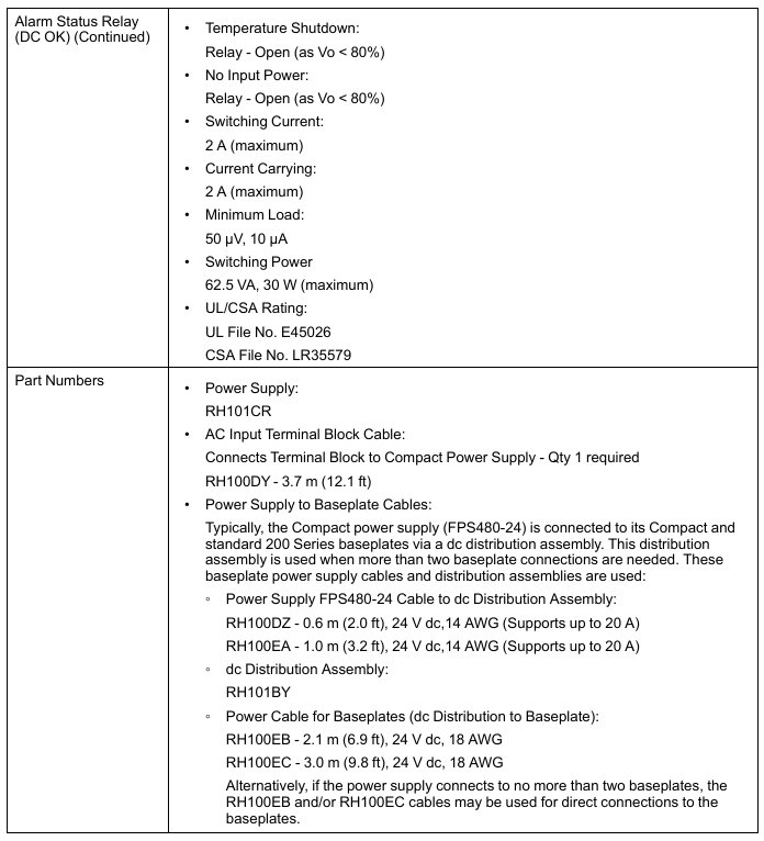
Relay alarm: The "DC OK" normally closed (NC) relay contacts close when the output voltage is greater than 80% of the rated value, and disconnect when it is less than 80% (such as short circuit, overload, or no input power). External alarm can be triggered by external modules such as FBM207b. The rated load of the relay contacts is 30V DC/1A, 110V DC/0.3A, 125V AC/0.5A, with insulation strength of 1000V AC (between contacts) and 1500V AC (between coils and contacts).
Environment and Compliance
(1) Environmental tolerance
Environmental indicators, operating range, storage range
Temperature -25~70 ° C (-13~158 ° F), linear load derating at 60-70 ° C -40~70 ° C (-40~158 ° F)
Relative humidity 5-95% (no condensation) 5-95% (no condensation)
Altitude -300~3000m (-1000~10000ft) -300~12000m (-1000~40000ft)
Vibration<19.6m/s ² (2G)-
(2) Electromagnetic Compatibility (EMC) and Safety Certification
EMC compliance: Compliant with IEC/EN 60950, UL60950-1, UL508, Semi F47 (only 200V AC) and other standards, with conducted emission (EN55022-B/CISPR22-B), radiated emission (EN55022-B/CISPR22-B), harmonic current (IEC61000-3-2 Class A) and other indicators meeting standards. Anti interference capabilities include: 8kV contact discharge/15kV air discharge (ESD), 2kV electrical fast transient (EFT), 2kV line to ground/4kV line to neutral lightning surge, 10V conducted RF common mode interference, etc.
Safety certification: UL file number E45026, CSA file number LR35579; ATEX certification (Ex nA IIC T3), CENELEC certification, meeting the requirements for use in hazardous areas; California Proposition 65 Warning: Products containing lead and lead compounds may cause cancer or reproductive harm. For more information, please refer to www.p65warnings. ca.gov.
Accessories and Connection Configuration
(1) Core accessory model
Accessory name, model, and purpose
The RH101CR core power supply unit of the power host provides 24V DC/20A output
AC input terminal block cable -1 cable is required to connect the terminal block to the power host
Connect the power supply to the Compact/Standard 200 series motherboard using RH100DY (3.7m), RH100DZ (0.6m), and RH100EA (1.0m) cables, with 14AWG supporting 20A current
DC distribution component RH101BY is used for multi board connection to achieve power distribution
Bottom board power cable (distribution component to bottom board) RH100EB (2.1m), RH100EC (3.0m) 18AWG, directly connecting the distribution component to the bottom board, supporting up to 2 bottom board direct connections
(2) Connection precautions
If only 1-2 base plates are connected, RH100EB/RH100EC cables can be directly used; If more than 2 baseboards are connected, power must be distributed through the RH101BY distribution component to avoid current overload.
It is recommended to use an independent power supply for external on-site equipment to avoid non system loads affecting the stability of DCS system power supply; All wiring must be fastened with M3 screw terminals to ensure reliable contact.
Key points for use and maintenance
Calibration requirements: The power supply is pre-set with a 24.0V DC output at the factory, which does not require user calibration or voltage adjustment, reducing maintenance workload.
Fault handling: After shutting down due to overvoltage/overcurrent, the input power supply should be disconnected first (within 30 seconds), and load faults (such as short circuits and overloads) should be checked before powering on again to restore power; When the "DC OK" relay is disconnected, it is necessary to check whether the output voltage is less than 80% of the rated value (19.2V DC), and troubleshoot input power supply, load, or internal power supply faults.
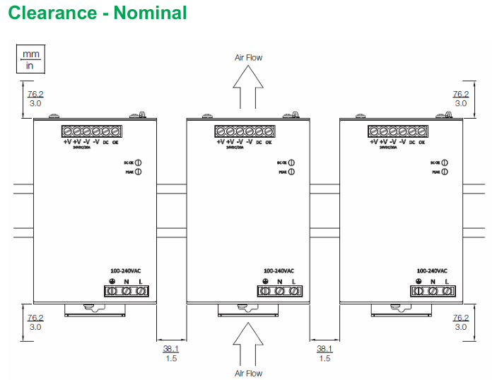
Installation spacing: To ensure natural convection heat dissipation, a ventilation gap of at least 76.2mm (3.0in) should be reserved around the power supply to avoid installation in close proximity to heating equipment.
- YOKOGAWA
- Reliance
- ADVANCED
- SEW
- ProSoft
- WATLOW
- Kongsberg
- FANUC
- VSD
- DCS
- PLC
- man-machine
- Covid-19
- Energy and Gender
- Energy Access
- Renewable Integration
- Energy Subsidies
- Energy and Water
- Net zero emission
- Energy Security
- Critical Minerals
- A-B
- petroleum
- Mine scale
- Sewage treatment
- cement
- architecture
- Industrial information
- New energy
- Automobile market
- electricity
- Construction site
- HIMA
- ABB
- Rockwell
- Schneider Modicon
- Siemens
- xYCOM
- Yaskawa
- Woodward
- BOSCH Rexroth
- MOOG
- General Electric
- American NI
- Rolls-Royce
- CTI
- Honeywell
- EMERSON
- MAN
- GE
- TRICONEX
- Control Wave
- ALSTOM
- AMAT
- STUDER
- KONGSBERG
- MOTOROLA
- DANAHER MOTION
- Bentley
- Galil
- EATON
- MOLEX
- Triconex
- DEIF
- B&W
- ZYGO
- Aerotech
- DANFOSS
- KOLLMORGEN
- Beijer
- Endress+Hauser
- schneider
- Foxboro
- KB
- REXROTH
- YAMAHA
- Johnson
- Westinghouse
- WAGO
- TOSHIBA
- TEKTRONIX
- BENDER
- BMCM
- SMC
- HITACHI
- HIRSCHMANN
- XP POWER
- Baldor
- Meggitt
- SHINKAWA
- Other Brands
- UniOP
- KUKA
- IBA
- Beckhoff
-
ADLINK cPCI-6626 - 6U CompactPCI 2.0 Blades i7-2710QE PCB-I-E-2570=9N41
-
ADLINK MXC-6322D(G) - Industrial Fanless Computer
-
ADLINK cPCI-8168-004 - CompactPci NulPC Motion Control Board 51-36402-0A3
-
ADLINK CPCI-7300[G] - COMPACTPCI Digital I/O Card Data Acquisition
-
ADLINK CPCI-6626/2710/M4G - COMPACTPCI COMPUTER BOARD
-
ADLINK cPCI-8168-009 - cPCI NulPC Motion Control Board
-
ADLINK cPCI-6626/2710/M4G - VME CPU Board Computer Board
-
ADLINK CPCI-R6200(G)-0040 - COMPACTPCI CONTROL BOARD
-
ADLINK CPCI-3840/PM18/M1G(G)-3650 - COMPACTPCI CPU Module Single Board Computer
-
ADLINK cPCI-7248 - 48-CH Opto-22 Compatible Digital I/O Module
-
ADLINK DLAP-211-JNX - NVIDIA Jetson Xavier NX Edge AI Inference Platform
-
ADLINK cPCI-3544 - Series 4-Port RS-422/485 Isolated Serial Communications Card
-
ADLINK CM1-86DX3 - PC/104 SBC Stanley Vortex86DX3 CPU 2GB Ram
-
ADLINK DLAP-211-JNX - NVIDIA Jetson Xavier NX Edge AI Inference Platform
-
ADLINK cPCI-3544 - Series 4-Port RS-422/485 Isolated Serial Communications Card
-
ADLINK CM1-86DX3 - PC/104 SBC Stanley Vortex86DX3 CPU 2GB Ram
-
ADLINK PCI-7433 - switch value acquisition card Isolated Digital Input Card
-
ADLINK PCI-9112 - 51-12252-0D20 Multi-Function Data Acquisition Card
-
ADLINK NUPRO-A301 REV:1.4 - industrial control motherboard PICMG Full-Size SBC
-
ADLINK 51-18502-0A10 - Frame Grabber Image Acquisition Interface Card
-
ADLINK PCI-7296 - 51-12009-0A50 PCB-I-E-925=6DX1 96-CH Parallel Digital I/O Board
-
ADLINK PCI-8132 GP A2 - Motion Control Card 2-Axis Servo & Stepper Controller
-
ADLINK PCI-7442 - switch quantity card data acquisition card 64-CH Isolated Card
-
ADLINK HPX-13S4 - baseboard PICMG 1.3 Passive Backplane Chassis Baseplate
-
ADLINK NuPRO-590 / NTC-567-ZM-F36 - Single Board Computer PCB-I-E-1853=9L21 Half-Size SBC
-
ADLINK PCIe-8332 - 16-axis plate Motion Control Hardware Card
-
ADLINK NuPRO-775 REV.B1 - motherboard Pentium 4 Full-Size PICMG SBC
-
ADLINK PXI-3920 - Embedded Controller 3U PXI cPCI System Intelligence Board
-
ADLINK PCI-8134 - driver card motion control card 4-Axis Controller Board
-
ADLINK HSL-DI32-M-N-011 / HSL-TB32-M-DIN - Digital Input & Base Module PLC Distributed I/O System
-
ADLINK PCI-6216V-206 / PCI-208V 009 - 16 CH 16bit analog output card
-
ADLINK NuPro-E330 - 51-41805-0A20 PCB Single Board Computer Host Board
-
ADLINK PCI-1622C - Card 8-Port RS-232/422/485 PCI Serial Communication Board
-
ADLINK PCIe-7432 - 51-18402-0A10 Carte PCIe Avec Plage D'Entrée Élevée Isolated DIO Card
-
ADLINK PCI-7250 - PCI Acquisition Card 8-CH Relay Output Isolated DI Card
-
ADLINK PCI-7230 - 32-CH Isolated Digital I/O Card
-
ADLINK PCI-8164 - PCB 4-Axis Motion Controller Card
-
ADLINK PCI-7854 - Collection card High-Speed Link Distributed Motion Controller
-
ADLINK NuPRO-935A/LV - industrial control computer motherboard Full-Size PICMG SBC
-
ADLINK IMB-M40H - motherboard IH61-AA4 1155 LGA1155 Micro-ATX Mainboard
-
ADLINK PCI-7248 - Linhua 51-12006-0A40 48-CH Parallel Digital I/O Card
-
ADLINK HPCI-14S12U - Linhua industrial computer baseboard Passive Backplane
-
ADLINK PCI-8132 Rev.A2 - 2-Axis Servo & Stepper Motion Controller Card
-
ADLINK ACL-8111 - ISA card Multi-Function DAQ Card
-
ADLINK ACL-8111 - ISA card Multi-Function Data Acquisition Board
-
ADLINK PCI-7200 REV.A3 - Digital I/O card 12MB/s High-Speed Parallel Digital I/O
-
ADLINK PCI-7296 REV.A3 - 96-CH High-Density Opto-Isolated DIO Card
-
ADLINK PCI-7434 - 64-CH Isolated Digital Output Card
-
ADLINK M-342 - atx motherboard Industrial PC Mainboard
-
ADLINK NuPRO-935ADV (A) 1.9 - CPU Board Intel Core 2 Quad CPU Q9500 2.83GHz PICMG Board
-
ADLINK NUPRO-935A/DV - motherboard dual network port 51-41802-0A10 CPU Board
-
ADLINK PCI-RTV24 - image capture card Analog Video Frame Grabber Board
-
ADLINK HPX-13S4 - device baseboard PICMG 1.3 Passive Backplane Chassis Baseplate
-
ADLINK PCI-8134A - control card 4-Axis Motion Controller Card
-
ADLINK ACL-7130 REV. B2 - industrial control capture card Isolated Digital I/O Board
-
ADLINK EBP-13E2 - Industrial Backplane Board Passive Backplane Baseboard
-
ADLINK NuPRO-935ADV (A) 1.9 - CPU Board Intel Core 2 Quad CPU Q9500 2.83GHz PICMG SBC
-
ADLINK PCI-8134A - motion control card 4-Axis Pulse-Train Controller Card
-
ADLINK PCI-9112 REV A.1 - Multi Function DA&C Board Data Acquisition Card
-
ADLINK 51-12001-0C20 - Circuit Board Multi-Function Data Acquisition Hardware
-
ADLINK PCI-7300A - 80-CH High-Speed Digital I/O Card
-
ADLINK PCI-7230 - 16-CH Isolated Digital Input Output Card
-
ADLINK DIN-814-GP - motion control module Interface Terminal Block
-
ADLINK NUPRO-A40H - 51-41807-1A20 Industrial Control Motherboard LGA1155
-
ADLINK PCI-7433 rev A2 - Isolated Digital Input Card
-
ADLINK NuPRO-780 - Pentium III 800 512 MB SBC NuPRO780 51-41309-0B2 Single Board Computer
-
ADLINK PCI-7853 / PCI-7854 - Acquisition card High-Speed Link Control Card
-
ADLINK NUPRO-852 / NUPRO-852LV - Industrial motherboard Full-Size PICMG CPU Board
-
ADLINK NuPRO-842LV/P - 51-41360-0B30 Industrial Motherboard Half-Size PICMG SBC
-
ADLINK PCI-FIW64 - 4/2 Channel IEEE1394B Image Capture Card Frame Grabber
-
ADLINK PCI-7851 Rev A1.1 - HSL system card High-Speed Link Master Controller
-
ADLINK PCI-7230 - 51-12003-0A50 card 32-CH Isolated Digital I/O Card
-
ADLINK NuPRO-841REV:1.0 - Industrial CPU Board Mainboard
-
ADLINK NuPRO-841 REV:1.0 - motherboard Industrial Control PC Mainboard
-
ADLINK PCI-8256 - 8-Axis Advanced Motion Control PCI Board
-
ADLINK PCI-6S / PCI6S - Backplane 6-Slot Passive Backplane Board
-
ADLINK PCI-7234 REV B3 - 32-CH Isolated Digital Output PCI Card
-
ADLINK PCI-8213 - HannStar MV-4 51-45003-0b4 Board
-
ADLINK PCI-7233 - 51-12004-0a20 board PCI7233 32-CH Isolated Digital Input Card
-
ADLINK PCI-7851 - 006 51-24003-0B20 High-Speed Link Master Motion Control Card
-
ADLINK PCI-7432 - 64-CH Isolated Digital I/O PCI Cards
-
ADLINK LPCI-3488 - Card Low Profile IEEE-488 GPIB Interface Card
-
ADLINK HPCI14S REV.B1 - industrial control computer base plate Passive Backplane
-
ADLINK NEON-1020 - Industrial camera Smart Camera Vision System
-
ADLINK PCI-7432 - Isolated Digital I/O PCI Card 64-CH
-
ADLINK Pcm-7250+ - 8-Ch Relay Outputs & 8-Ch Isolated DI Module PC/104
-
ADLINK CPCI-7841 - DUAL-PORT ISOLATED CAN INTERFACE CARD CompactPCI
-
ADLINK PCI-3488 / PCI-GPIB - PCI IEEE-488 GPIB Interface Card
-
ADLINK PCI-1711U - Card Multi-Function Data Acquisition Board
-
ADLINK NUPRO-A301 - REV:1.1 1.2 1.4 PICMG Full-Size Single Board Computer
-
Adlink DIN-50S-01 - PLOTECH 51-14024-0A40 50-pin Wiring Terminal Board
-
Chroma 52962 / 58183 - PXI Optical Spectrometer carrier adapter Card
-
ADLINK PCI-6208V - PCI DATA ACQUISITION & RECORDING CARD 8-CH Analog Output
-
ADLINK HSL-DI32-DB-N - Industrial Control Board Distributed Digital Input Module
-
ADLINK HSL-AO4-U - 4-CH HIGH SPEED LINK ANALOG OUTPUT MODULE Distributed I/O
-
ADLINK PCI-7396 - 0050 GP 51-12012-0B20 96-CH High-Speed Digital I/O Card
-
ADLINK NUPRO-935A/DV - 51-41802-0A10 motherboard Industrial CPU Single Board Computer
-
ADLINK PCI-9111 DG - Industrial Acquisition Card Multi-Function DAQ Card
-
ADLINK NuPRO-E315 - industrial computer motherboard Intel Atom SHB SBC
-
ADLINK NUPRO-406 REV:B1 - Industrial Control Motherboard Full-Size PICMG CPU Board
-
ADLINK NuPRO-E330 - motherboard Industrial Control System Host Board PICMG 1.3
-
ADLINK ACL-6128A 103 - 51-11002-1A4 2-CH Isolated Analog Output Card
-
XTRAMUS cPS-H325/AC - POWER SUPPLY NUSTREAMS 600 NETWORK TESTING EQUIPMENT Power Module
-
ADLINK DIN-814P-A4 - 51-14056-0A10 Terminal Block Motion Control Breakout Board
-
ADLINK TB-24P/24-01 - 24-Channel Card Terminal Breakout Board
-
ADLINK PCI-7251 - 51-12008-0A30 PCI7251 8-CH Relay Output Isolated Digital Input Card
-
ADLINK HSL-TB64-DIN REV A1 / HSL-DO32-DB-N - 2ea Board Breakout Terminal Board Distributed I/O Module
-
ADLINK NuPRO-865 REV 3.0 - industrial computer motherboard Full-Size PICMG SBC
-
ADLINK NUPRO-A40H - motherboard 51-41807-1A30 OSP H61 Industrial PC Mainboard
-
ADLINK LPCI-3488A - PCI Card 51-12801-0A30 GPIB Interface Card
-
ADLINK DIN-825-4P0 - 51-14085-0A30 Terminal Printed Circuit Board Breakout Block
-
ADLINK IMB-T10/D2550 V - MOTHER BOARD 80-PXG160-A1A01 IMB-T10-M2G-S32G Industrial Mainboard
-
ADLINK PCI-8144N - Motion Control card Stepper Motor Controller
-
ADLINK PCI-7433 - Digital acquisition card Isolated Digital Input Card
-
ADLINK PCI-9112 DG - Data Acquisition card 51-12252-0D20 Multi-Function DAQ
-
ADLINK IMB-M40H - motherboard IH61-AA4 1155 LGA1155 Micro-ATX Mainboard
-
ADLINK TB-24P/24-01 - Carte 24 voies Terminal Breakout Board Connector Module
-
ADLINK HSL-D16DO16-M-NN - Distributed Discrete Input Output I/O Module
-
ADLINK PCI-7248 - PCI CARD 51-12006-0A40 48-CH Parallel Digital I/O Board
-
ADLINK HSL-DI32-DB-N - Industrial Control Board Distributed I/O Digital Input Module
-
ADLINK PCI-7433 - Pci 7433 Isolated Digital Input Card
-
ADLINK PCI-6208V - 008 Data acquisition card 8-CH Analog Output Card
-
ADLINK IH61-AA4 - industrial motherboard LGA1155 Micro-ATX Mainboard
-
ADLINK PXI-3920 - PXI 3U cPCI Industrial Controller Embedded System CPU Board
-
ADLINK PCI-6308 - Analog Output DAQ Card Isolated Voltage Output Card
-
ADLINK PCI-7200 - data acquisition card REV.A3 High-Speed Parallel DIO Card
-
ADLINK NuPRO-E315 - Industrial Control Computer Motherboard PICMG 1.3 SHB SBC
-
ADLINK PCI-1610C - Card 4-Port Isolated RS-232 PCI Serial Communication Card

K-JIANG

Add: Jimei North Road, Jimei District, Xiamen, Fujian, China
Tell:+86-15305925923