
K-WANG


SIEMENS G120 CU240BE-2 frequency converter
SIEMENS G120 CU240BE-2 frequency converter
Detailed analysis of parameter system
(1) Basic rules for parameters (supplementary configuration logic)
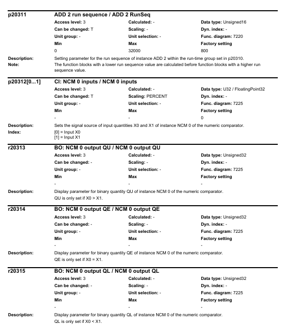
Parameter number and type
Number format: Read and write parameters starting with "p" (such as p0003), read-only parameters starting with "r" (such as r0002, displaying the running status of the driver);
Index identifier: with [0... n] indicating multiple index parameters (such as p0304 [0... n], supporting storage of multiple motor parameters);
Bit field identifier: with. 0... n represents bit parameters (such as r0046.0, corresponding to the switch status of specific functions).
Parameter access and modification rules
Access level control: Set through P0003, Level 3 (expert level) includes 1-2 levels of functionality, and Level 4 (service level) requires a password (p3950) to unlock;
Modification effective conditions: Some parameter annotations "C (x)" indicate that they can only be modified in debugging mode (p0010=x), "U" indicates that they can be modified during operation, "T" indicates that they can be modified in the ready state, and some parameter modifications require restarting the frequency converter to take effect;
The impact of associated parameters: The "Linked parameterization" feature automatically synchronizes the modification of associated parameters when modifying some parameters (such as p0922 PROFIBUS telegram), and the impact range needs to be confirmed in advance.
(2) Detailed analysis of core parameter module
1. Basic configuration parameters (p0000-p0999)
Parameter Number Parameter Name Core Function Value Range Default Values Key Explanation
The parameter range that can be viewed/modified in the access level control of P0003 is 3 (expert), 4 (service), and 3/4. The password p3950 is required for level 4, and only authorized service personnel can operate it
P0010 Debugging parameter filter filters visible parameters at different debugging stages 0-95 1 0=ready, 1=fast debugging, 3=motor debugging, 15=dataset configuration, 30=parameter reset, 95=safety integration debugging
P0015 Driver Unit Macro Run Preset Macro File, Quickly Configure Typical Application Scenarios 0-999999 7 (CU240B-2)/12 (CU240E-2) After Execution, Parameter Lock, R3996=0 is Required to Modify Again
P0096 Application class switching control view (adapted to different application scenarios) 0=Expert, 1=Standard drive control, 2=Dynamic drive control 0 1=Suitable for standard loads such as pumps/fans, 2=Suitable for high dynamic response loads (such as machine tools)
P0100 Standard Selection (IEC/NEMA) Switching Motor Parameter Unit System 0=IEC, 1=NEMA, 2=NEMA+SI 0 0=Power Unit kW, Frequency 50Hz; 1=Power Unit hp, Frequency 60Hz
P0170 Command Dataset Quantity (CDS) Configuration: The number of storable command datasets is 2-4. 2 Supports quick switching of different control commands (such as manual/automatic frequency source switching)
P0180 Driver Dataset Quantity (DDS) Configuration: The number of storable driver datasets ranges from 1 to 4, and supports fast switching of different motor or load parameters (such as multiple motors sharing a frequency converter)
2. Motor parameters (p0300-p0399)
The core is used to match the motor nameplate data, which directly affects the control accuracy and protection function, and is a key debugging step:
Parameter Number Parameter Name Core Function Value Range Default Values Key Explanation
P0300 Motor type selection definition: Motor type 0=no motor, 1=induction motor, 2=synchronous motor, etc. After selecting 0, the corresponding motor parameters will be automatically filtered. If the synchronous motor does not display the exclusive parameters of the induction motor
P0301 motor code number: Select motor model 0-65535 from the built-in motor parameter list. 0=manually input parameters,>0=load preset parameters from Siemens motor database
The rated voltage input on the motor nameplate of P0304 motor is 0-20000 Vrms, which needs to be matched with the supply voltage. When connected in a star/delta configuration, it needs to be adjusted accordingly (such as the delta connection voltage being √ 3 times that of the star configuration)
The rated current input on the motor nameplate of P0305 motor is 0.00-10000 Arms 0.00, which directly affects the overcurrent protection threshold (p2100). Setting the wrong value may cause protection to trigger incorrectly or the motor to burn out
P0307 motor rated power input: The rated power on the motor nameplate is 0.00-100000 kW. The IEC standard unit is kW, and the NEMA standard unit is hp (when P0100=1)
P0310 motor rated frequency input: The rated frequency on the motor nameplate is 0.00-650.00 Hz. The default is 50Hz (IEC)/60Hz (NEMA), which affects the speed calculation (n=60f/p, p is the number of pole pairs)
The rated speed input on the nameplate of the P0311 motor ranges from 0.0 to 210000 rpm. 0.0 is used as the reference value for speed closed-loop control and, together with P0310, determines the number of motor poles (r0313)
P0340 automatically calculates parameters based on nameplate data to automatically calculate motor equivalent circuit parameters and control parameters 0-50 1=complete calculation, 2=motor parameter calculation, 3=closed-loop control parameter calculation, 4=controller parameter calculation, 5=threshold calculation
3. Control mode and speed parameters (p1000-p1999)
Parameter Number Parameter Name Core Function Value Range Default Values Key Explanation
P1000 frequency setting source selection frequency converter output frequency control mode 0-10 2 0=none, 1=terminal, 2=analog, 5=communication, 7=PID, 10=process controller
P1080 Minimum output frequency limit: The minimum output frequency of the frequency converter is 0.00-600.00 Hz to prevent overload during low-speed operation of the motor (such as pump loads to avoid idling)
P1082 Maximum output frequency limit: The maximum output frequency of the frequency converter should not exceed 1.2 times the rated frequency of the motor (p0310), from 0.00-600.00 Hz to 50.00/60.00 Hz, to avoid motor overspeed damage
P1120 Acceleration time from 0 to maximum frequency rise time 0.01-6500.0 s 10.0 The greater the load inertia, the longer the acceleration time needs to be to prevent overcurrent tripping
The descent time from maximum frequency to 0 for p1121 deceleration time is 0.01-6500.0 s 10.0, which needs to be matched with the load braking demand. For large inertia loads, the deceleration time needs to be extended or braking resistors need to be configured
P1300 control mode selection: The core control algorithm of the frequency converter is 0-22. 20=V/f control, 20=vector control (without encoder), 21=vector control (with encoder), 22=torque control
P1900 motor recognition automatically identifies motor equivalent circuit parameters, optimizes control accuracy 0-3 20=disabled, 1=static recognition, 2=dynamic recognition (motor idling required), 3=precise recognition
4. Fault protection parameters (p2100-p2299)
Parameter Number Parameter Name Core Function Value Range Default Values Key Explanation
P2100 overcurrent protection threshold setting: The upper limit of overcurrent protection current is 1.0-2.0 times the rated current, and 1.5 times the rated current. If the threshold is exceeded, the frequency converter will immediately trip to avoid damage to the power module
P2175 overvoltage protection threshold setting DC bus overvoltage protection threshold 1.0-1.3 times rated voltage 1.15 times suitable for voltage fluctuation scenarios in the power grid. If the threshold is too high, it may cause capacitor damage
P2176 undervoltage protection threshold setting DC bus undervoltage protection threshold 0.7-0.9 times rated voltage 0.85 times lower than the threshold, the frequency converter will operate at reduced capacity or trip to prevent insufficient motor torque
P2200 motor overheat protection enable/disable motor overheat protection function 0=disable, 1=enable 1 Based on motor temperature model (p0612) or temperature sensor signal, rated or tripped when overheated
P2260 torque limit motor output torque 0.0-200.0% 150.0% to prevent motor damage caused by load overload, which needs to be adjusted according to the rated torque of the load
5. Communication parameters (p2000-p2099)
Parameter Number Parameter Name Core Function Value Range Default Values Key Explanation
P2010 communication address (PROFIBUS/Modbus) setting: The address 1-126 of the frequency converter in the communication network should be consistent with the configuration of the upper computer (PLC/HMI) to avoid address conflicts
P2023 Communication Baud Rate (Modbus) Set the transmission rate of Modbus communication to 9600/19200/38400/115200 bps. The higher the baud rate, the faster the transmission speed, but it is limited by the communication distance (such as 115200bps, recommended distance<10m)
P2080 PROFIdrive status word mapping configuration for PROFIBUS/PROFINET status word signal source 0-65535 0 defines the operating status signals (such as ready, fault, running) fed back by the frequency converter to the PLC
P2081 PROFIdrive control word mapping configuration PROFIBUS/PROFINET control word signal source 0-65535 0 defines the control commands sent by PLC to the frequency converter (such as start stop, frequency setting, fault reset)
6. Input/Output (I/O) Parameters (p0700-p0799)
Parameter Number Parameter Name Core Function Value Range Default Values Key Explanation
P0700 Definition of Digital Input Function Allocation: Functions of Digital Input Terminals (DI) 0-99 2 0=No Function, 1=ON/OFF 1, 2=ON/OFF 2 (Emergency Stop), 3=ON/OFF 3 (Quick Stop)
P0730 Digital Output Function Allocation (DO0) defines the function of the digital output terminal (DO0) from 0 to 99. 52.0 0=no function, 52.0=ready state, 52.3=fault state, 52.7=alarm state
P0756 Analog Input Type (AI0/AI1) Set the signal type of the analog input terminal to 0-8 4 0=0-10V voltage input, 2=0-20mA current input, 3=4-20mA current input, 4=-10V~+10V bipolar voltage
P0771 Analog Output Function Allocation (AO0) defines the signal source 0-99 of the analog output terminal (AO0). 21.0 0 0=no function, 21.0=output frequency, 27.0=output current, 28.0=output voltage
(3) Read only parameters and status monitoring (r series)
The manual provides a detailed list of R-series read-only parameters for real-time monitoring of equipment operation status. The core parameters are as follows:
R0002: Driver operating status (e.g. 0=everything is normal, 10=need to activate set value, 35=need initial debugging);
R0021: Actual speed (smoothed), in rpm, reflecting the real-time speed of the motor;
R0025: Output voltage (smoothed), in Vrms, monitor the output voltage of the frequency converter;
R0027: Output current (smoothed), in Arms, to determine if the motor is overloaded;
R0031: Actual torque (smoothed), in Nm, reflecting the magnitude of the load torque;
R0052: Status word 1, displaying device ready, running, fault and other statuses through bit fields (such as bit0=ready, bit3=fault);
R0207: Rated current of power unit, reflecting the rated capacity of the inverter hardware;
R2135: Fault/alarm status word, records current or historical fault codes.
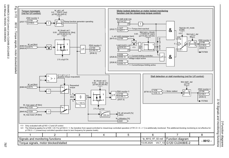
(4) Functional diagrams and logical associations
Chapter 3 of the manual provides detailed 590 page functional diagrams, covering:
Input/output terminal wiring logic (such as signal flow direction of DI/DO/AI/AO);
PROFIdrive communication protocol interaction logic (PROFIBUS/PROFINET data frame structure);
Control mode logic (such as speed closed-loop and torque closed-loop processes of vector control);
Fault protection logic (such as detection and tripping processes for overcurrent and overvoltage);
BICO parameter interconnection logic (such as the signal correlation between BI parameters and BO parameters).
Functional diagrams use standardized symbols to label parameter numbers and signal flow directions, helping technicians understand the underlying logic of parameter configuration. For example, the "speed control closed-loop" diagram clarifies the complete process of comparing r0021 (actual speed) and p1070 (speed set value), PID regulation, and output drive.
(5) Troubleshooting and Alarm Handling (Chapter 4)
Fault/alarm classification
Faults: The equipment cannot operate normally and needs to be manually reset after troubleshooting (such as F30002=DC bus overvoltage);
Alarm: The device can still operate but there are abnormalities that need attention (such as A07012=motor overheating warning).
Troubleshooting process
Step 1: Read the fault code through r2135 or the operation panel;
Step 2: Search the manual for the corresponding cause of the fault code (such as F30005=power unit I2t overload);
Step 3: Check according to the manual recommendations (such as checking if the load is overloaded and if the heat dissipation is good);
Step 4: Modify the corresponding parameters (such as adjusting the p2260 torque limit) or reset after fixing hardware faults.
Common faults and troubleshooting examples
F30002 (DC bus overvoltage): The reason may be that the grid voltage is too high and the deceleration time is too short; The processing method is to adjust the overvoltage threshold of p2175, extend the deceleration time of p1121, and configure the braking resistor;
F30005 (power unit I2t overload): The reason may be continuous overload of the load or a malfunction of the cooling fan; The processing method is to reduce the load, check the fan, and adjust the p0290 overload response strategy;
F07011 (motor overheating): The possible reasons may be excessive motor load or temperature sensor malfunction; The processing method is to reduce the rated operation, check the sensor, and adjust the P0605 overheating threshold.
Example of Key Application Scenario Parameter Configuration
Scenario 1: Pump/Fan Load (Standard Drive Control, p0096=1)
Basic configuration: p0010=1 (quick debugging) → p0300=1 (induction motor) → Input p0304/p0305/p0307/p0310 (motor nameplate data);
Control mode: p1000=2 (analog frequency source) → p1300=0 (V/f control);
Protection configuration: p2200=1 (motor overheating protection) → p2260=110% (torque limit);
Operating parameters: p1080=1.0Hz (minimum frequency anti slip) → p1120=30s (extended acceleration time waterproof hammer) → p1121=30s (extended deceleration time);
Confirm save: p3900=1 (complete quick debugging) → Parameters automatically take effect.
Scenario 2: Machine tool spindle load (dynamic drive control, p0096=2)
Basic configuration: p0010=1 → p0300=1 → Input motor nameplate data → p1900=2 (dynamic motor recognition);
Control mode: p1000=5 (communication frequency source) → p1300=20 (vector control without encoder);
Dynamic parameters: p1400=3.0 (PID proportional coefficient) → p1401=0.1 (PID integration time) → optimized dynamic response;
Protection configuration: p2100=1.8 (overcurrent threshold) → p2260=150% (torque limit) → p2175=1.2 (overvoltage threshold);
Communication configuration: p2010=5 (communication address) → p2080=1 (status word mapping) → p2081=1 (control word mapping);
Confirm save: p3900=2 → Restart the frequency converter to take effect.
Precautions and Risk Warning for Use
Before parameter configuration:
Confirm the control unit model and firmware version (r0018) to ensure parameter compatibility;
Disconnect the motor load or ensure that the load is in a safe state to avoid accidental operation of the equipment during debugging;
Backup the original parameters (p0971=1) for easy recovery in case of configuration errors.
In parameter configuration:
Strictly input the parameters p0300-p0311 according to the motor nameplate, incorrect settings may cause the motor to burn out;
Parameters related to safety functions (such as p0930 safety integration parameters) need to be configured by authorized personnel, and failure to comply with safety standards may result in personal injury;
The communication parameters must be consistent with the upper computer, otherwise a communication connection cannot be established.
After parameter configuration:
Conduct no-load testing (no-load operation), monitor parameters such as r0021/r0027/r0031, and confirm that the equipment is running normally;
Gradually load the load, observe whether the protection function is triggered, and verify the rationality of the parameters;
Record key parameters (such as motor data, communication address) for easy maintenance in the future.
Common risk avoidance:
Avoid modifying the rated parameters of the motor (p0304, etc.) during operation, which may cause instantaneous overload tripping;
Do not set p0290 (overload response) to 1 (trip directly without derating) unless there is no possibility of overload on the load;
Incorrect setting of analog input type (voltage/current) (p0756) can result in abnormal frequency setting.
- YOKOGAWA
- Reliance
- ADVANCED
- SEW
- ProSoft
- WATLOW
- Kongsberg
- FANUC
- VSD
- DCS
- PLC
- man-machine
- Covid-19
- Energy and Gender
- Energy Access
- Renewable Integration
- Energy Subsidies
- Energy and Water
- Net zero emission
- Energy Security
- Critical Minerals
- A-B
- petroleum
- Mine scale
- Sewage treatment
- cement
- architecture
- Industrial information
- New energy
- Automobile market
- electricity
- Construction site
- HIMA
- ABB
- Rockwell
- Schneider Modicon
- Siemens
- xYCOM
- Yaskawa
- Woodward
- BOSCH Rexroth
- MOOG
- General Electric
- American NI
- Rolls-Royce
- CTI
- Honeywell
- EMERSON
- MAN
- GE
- TRICONEX
- Control Wave
- ALSTOM
- AMAT
- STUDER
- KONGSBERG
- MOTOROLA
- DANAHER MOTION
- Bentley
- Galil
- EATON
- MOLEX
- Triconex
- DEIF
- B&W
- ZYGO
- Aerotech
- DANFOSS
- KOLLMORGEN
- Beijer
- Endress+Hauser
- schneider
- Foxboro
- KB
- REXROTH
- YAMAHA
- Johnson
- Westinghouse
- WAGO
- TOSHIBA
- TEKTRONIX
- BENDER
- BMCM
- SMC
- HITACHI
- HIRSCHMANN
- XP POWER
- Baldor
- Meggitt
- SHINKAWA
- Other Brands
- UniOP
- KUKA
- IBA
- Beckhoff
-
LTI SC52.0040.0012.0000.0 - Servo Drive
-
Lti SC52.0040.0012.0000.0 - Servo Drive
-
Milton Industries LTI Tool By Milton LT1240 - 1/2" Drive Lugnut Remover
-
LTi Drives SO84.200.P030.0000.0-W - Servo Spindle Drive
-
LTI DRIVES LSP08-035-320-30-B0R1PY170 - Servo Motor
-
LTI DRIVES SE84.200.SC00.0001.0-W - Servo Drive
-
Lust CDE34.005.W2.2 - Lti Drives Controller
-
LTi SO84.012.0030.0011.2 - ServoOne Servo Drive
-
LTi Drives SO CM-P.0010.11.00.0 - Servo Drive Controller
-
LTi CDE34.017.W3.0 - Servo Drive
-
LTI Drives CDB32.004, C2.0,SH - Positioning Controller
-
LUST CM-CAN1 - LTi DRIVES Communication Module
-
LTi SO84.012.1030.0000.2 - Servo Drive
-
LTI MOOG CDE54.044 - PITCHMASTER FREQUENCY CONVERTER 181-01019
-
MOOG LTI 181-01019 CDE54.044 - PITCHMASTER FREQUENCY CONVERTER
-
Lust LTi Drives CDE34.010,D2.0 - Servo Drive Controller
-
LTI SO84.032.0003.0101.2 - Servo Drive
-
Seagate 9CC132-302 Harris LTI-CS IRT-34-0021-01 - Hard Drive 160GB
-
LTI SO84.032.0003.0001.2 - Servo Drive
-
LTI SO24.007.0070.0000.1 - SERVO CONTROLLER
-
LTi drive CDA32.003.C3.0.H05-01.PC1 - Servo Drive
-
LTI SO84.016.0030.0000.2 - SERVO CONTROLLER
-
LUST LTI CD A34.008,W1.4, BR - SERVO DRIVE
-
MOOG LTI 181-01019 CDE54.044 - PITCHMASTER FREQUENCY CONVERTER
-
LTI MOOG 181-01019 - PITCH Master Servo Drive CDE54.044
-
LTI SERVO ONE SO84.045.0030.0001.2-W - Drive
-
LUST LTi SO84.032.0040.0000.2 - SERVO ONE DRIVE
-
LTi Drives LSH-074-2-30-3 20/T1,G6.1M - SERVO MOTOR
-
LTI SO84.016.0000.0101.2 - servo drive
-
LTI SA54.0550.0033.0000.0 - Servo Drive
-
LTI SA54.0550.0033.0000.0 - Servo Drive
-
LTI LT 4850 - 3/8" Drive 3-Pc Twist Socket Transmission Drain Plug Removal System
-
LTI Tools LT4400-30 Lock Technology - 3/4" Twist Socket 1/2" Drive Lugnut Remover
-
LTI Tools LT-1400C - 1/2 Drive Wheel Torque Extension Tool
-
LTI Tools LT1250 - 1/2" Drive Dual Sided Socket Lug Nut Remover Tool
-
LTI SO84.032.0003.0101.2 - Servo Drive
-
LTI MOOG 181-01019 - PITCH Master Servo Drive CDE54.044
-
MOOG LTI 181-01019 CDE54.044 - PITCHMASTER FREQUENCY CONVERTER
-
MOOG LTI 181-01019 CDE54.044 - PITCHMASTER FREQUENCY CONVERTER
-
MOOG LTI 181-01019 CDE54.044 - PITCHMASTER FREQUENCY CONVERTER
-
LTI SA54.0550.0033.0000.0 - Servo Drive
-
LTI Tools LT-4800 - 7 Piece Twist Socket 3/8" Drive Oil Drain Plug Removal Set
-
LTI SA54.0550.0033.0000.0 - Servo Drive
-
LTI Drive SO24.007.00300000.0 - Servo Drive
-
LTI TOOLS LTI 1400-I - Drive Wheel Torque Extension
-
LTI Tools LT4400-3 - 3/4" 19mm Twist Socket 1/2" Drive Lugnut
-
LTI TOOLS LTI 1400-BB - Drive Wheel Torque Extension
-
LTI SO84.032.0003.0101.2 - Servo Drive
-
LTI Tools LT-4512 - 3/8" Drive 12mm Twist Socket
-
LTI MOTION Luster SO84.032.0003.0001.2 - Servo Drive
-
LTI Tool By Milton LT1600P - 1" Drive Torx Stick
-
LTI Lust VF1424L,HF,OP2,S56 - Variable Frequency Drive
-
LUST CDA32.004,C1.4,H08,B0 - SERVO DFRIVE CM-CAN1 Module
-
LTI SO84.045.0002.0001.2-W - Drive
-
LTI Lust VF1404M,C9,PT1,BR1 - Inverter Type VF1404M
-
LTI SA54.0550.0033.0000.0 - Servo Drive
-
LTI Tools LT-1400C - 1/2" Drive Wheel Torque Extension
-
Lust LTI DRiVES CDA32.006, C3.0, H09 - Variateur De Fr茅quence Frequency Inverter
-
LTI MOOG CDE54.044 - PITCH master SERVO DRIVE
-
LTI MOOG CDE54.044 - PITCH master SERVO DRIVE
-
LTI SO84.143.0020.0101.2-W - servo drive
-
LTI MOTION SC34.0200.0011.0000.0 - Servo drives
-
LTI SO84.032.0003.0001.2 - Servo Drive
-
LTI DRIVES GmbH MS100 - Assembly Set Mounting Kit
-
LTI SO84.032.0003.0001.2 - Servo Drive
-
LTI SO84.032.0003.0001.2 - Servo Drive
-
LTI MOTION SO84.032.0003.0101.2 - servo drive
-
LTI SO84.032.0003.0101.2 - Servo Drive
-
LTI MOOG CDE54.044 - PITCH master SERVO DRIVE
-
LTI MOTION CDE32.004.C2.4 - Servo drives
-
LTI CDD34.032锛學x.x锛孊R锛孭C1 - Servo Drive
-
Lust LTI DRiVES CDA32.006, C3.0, H09 - Inversor De Frecuencia Frequency Inverter
-
Lust SO84.008.0030.1000.0 - Servo One LTi Drive
-
LTI MOTION SO84.032.0003.0101.2 - Servo drives
-
LUST LTi CDA32.004,C1.4 - SERVO DRIVE
-
LTI MOOG CDE54.044 - PITCH Master SERVO DRIVE
-
LTI KEBA CDB32.004 C2.7, SH - PN: 08673530 Frequency Inverter
-
LTI Tools LT-1400C - 1/2" Drive Wheel Torque Extension
-
LTI LT1400-E - 1/2" Drive Wheel Torque Extension
-
LTI MOOG 181-01019 - PITCH master SERVO DRIVE CDE54.044
-
LTI LSN-097-0510-30-560/T1 - Actuator Motor
-
LTI Tools LT 4800 - 7 Piece 3/8" Drive Twist Socket Oil Drain Plug Removal System
-
LTI DRIVES GmbH MS100 - MONTAGESET Assembly Set Mounting Kit
-
Lti SC52.0040.0012.0000.0 - Servo Drive
-
LTI DRIVES GmbH MS100 - Juego De Montaje Assembly Set Mounting Kit
-
LTi DSM4-14.2-21R83-200 - Drives servomoteur Servo Motor
-
MOOG CDE 54.044.GDA - Pitch Master Industrielle Turbine Lti Drive
-
LTI SO24.004.0030.1000.0 - Servo Drive Controller
-
Lti MOOG CDE54.044 - Pitch Master Servo Drive
-
Lust LTI DRiVES CDA32.006, C3.0, H09 - Inverter
-
LTI MOTION GMBH CDB34.006,W3.0,PC1,H39 - Frequency inverter
-
LTI SO84.032.0003.0001.2 - Servo Drive
-
MOOG CDE 54.044.D - Pitch Master Industrielle Turbine Lti Drive
-
LTI TOOLS LT-1460 - 1/2" DRIVE WHEEL TORQUE EXTENSION KIT 5 PIECE SET
-
Lust Cdb32.003, C2.4 - Lti Drives Servoregulador Frecuencia Servo Controller Inverter
-
Lust LTI DRIVES CDA32.006, C3.0, H09 - Frequency Inverter
-
Lust Lti SO82.004.0030.0000.2 - Servo Drive
-
LTI MOTION SC34.0200.0011.0000.0-SL - Servo drives
-
LTI MOTION SA54.0075.0033.0000.0 - Servo drives
-
LTI MOTION SC32.0075.1011.0000.0 - Servo drives
-
Lust Cdb32.003, C2.4 - Lti Drives Servo Controller Frequency Inverter
-
LTI MOOG CDE54.044 - PITCH master SERVO DRIVE
-
Lust Lti Cde34.006,W2.0,Br - Servo Drive
-
Lust LTi MOTION CDE34.044,W2.4,H13 - Servo Drive
-
Lust LTi Drives Cde32.008, W2.2.br - Positionierregler Posici贸n Mando Positioning Controller
-
LTI MOOG CDE54.044 - PITCH master SERVO DRIVE
-
LUST Antriebstechnik B-DS 125.1 - LTi DRiVES Accessories Drive Component
-
LTi LSMM13-100-4N-001 - servo motor
-
Lti CDA32.004 C1.4, H08, B0 - PN: 3084456 Frequency Inverter
-
LTI MOTION CDE34.006.WXX.PC1 - Servo drives
-
LTI MOTION SO24.007.0030.1000.0 - Servo drives
-
Lust CDD34.005.C2.1 - LTI Drive
-
Lti SC52.0040.0012.0000.0 - Servo Drive
-
LTI Tools LT4400-30 - 1/2" Drive 19mm 3/4" Twist Socket
-
Lust LTi Drives Cde32.008, W2.2.br - Positionierregler Posici贸n Mando Positioning Controller
-
LTI MOOG CDE54.044 - PITCH master SERVO DRIVE
-
LUST Antriebstechnik B-DS 125.1 - LTi DRiVES Accessories Drive Component
-
LTI DRIVES GmbH MS100 - MONTAGESET Assembly Set Mounting Kit
-
Lust LTi SO84.032.0043.0000.2 - Servo one Drive
-
LUST LTi Drives CM-CAN1 - Modulo Di Comunicazione Communication Module
-
LTI drive CDF 30.008.C3.6 - Servo Drive
-
LTI MOOG 181-01019 - PITCH master SERVO DRIVE
-
LTI CDB34.014,W2.4,BR,SH - Servo Driver
-
Lti SC52.0040.0012.0000.0 - Servo Drive
-
LTi Drive CDF30.002 - Power Supply Fuse
-
LTI Tools LT-4621-D - Deep Well Twist Socket 3/8" Drive 1/2"
-
LTI MOOG PITCH master CDE54.044 - SERVO DRIVE Frequency Converter
-
LTI SO84.076.S030.0001.2-W - Servo One Drive

K-JIANG

Add: Jimei North Road, Jimei District, Xiamen, Fujian, China
Tell:+86-15305925923