
K-WANG


SIEMENS SINAMICS G120 Control Unit CU240E
The default control and monitoring signal source for the control unit is the wiring terminal, which can be modified during debugging through parameters P0700 (command signal source) and P1000 (set value signal source).
SIEMENS SINAMICS G120 Control Unit CU240E
Detailed installation process explanation
1. Installation of core prerequisites
The control unit (CU240E) and power module need to work together and cannot operate separately; If installed incorrectly, it may cause the frequency converter to start unexpectedly, so the installation must be completed by certified personnel who have received training in the installation of such systems.
The default control and monitoring signal source for the control unit is the wiring terminal, which can be modified during debugging through parameters P0700 (command signal source) and P1000 (set value signal source).
2. Equipment structure and status indication
(1) Key Structure
Status indicator: includes a red SF (system fault) indicator light and a green RDY (ready) indicator light.
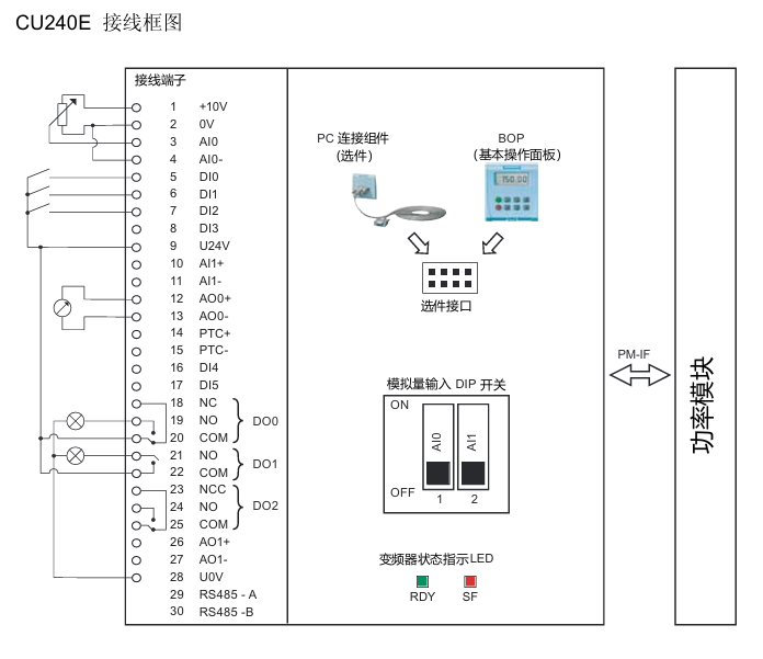
Core interfaces: analog input interface, power module interface, control terminal, bus termination switch, shielding layer card, option interface (supporting BOP basic operation panel and other options).
(2) Definition of Core Terminals in Wiring Diagram
Terminal Number Function Description Terminal Number Function Description
1 +10V 15 PTC-
2 OV 16 DI4
3 AIO 17 DI5
4 AI0- 18 NC
5 DIO 19 NO(DO0)
6 DI1 20-23 COM, NCC, NO, COM (DO1 related)
7 DI2 24 NO(DO2)
8 DI3 25 COMJ
9 U24V 26 AO1+
10 AI1+ 27 AO1-
11 AI1- 28-29 RS485 -A、UOV
12 AO0+ 30 RS485 -B
13 AO0- - -
14 PTC+ - -
3. Technical parameters of wiring terminals
Design type: Cage spring clamping design, compatible with cable specifications of 0.2~1.5 mm ² (24~14 AWG).
I/O interface configuration: 6 digital inputs (DI), 3 digital outputs (DO), 2 analog inputs (AI), 2 analog outputs (AO), and 1 PTC interface.
Cable requirements: The maximum length of the control cable should not exceed 10 meters (32.8 feet); Unshielded cables can work, but it is recommended to use shielded cables to meet the EMC (electromagnetic compatibility) requirements of CE standards.
4. Bus connection (USS protocol)
Connection method: RS485-UPS bus connection is made through terminals 29 (RS485-A) and 30 (RS485-B).
Transmission rate: The maximum baud rate is 115200 baud.
Terminal switch: The bus terminal switch is located below terminals 29 and 30 and needs to be set according to the bus topology requirements.
5. Installation and disassembly operations
Installation: The control unit is fixed on the power module by card mounting, and the installation and operation of all G120 control units and G120 power modules are completely consistent, without distinguishing models.
Disassembly: Press the release button on the top of the power module to remove the control unit from the power module.
Pre power on inspection (14 mandatory items)
Before powering on, the following checks need to be completed one by one to ensure that the system has no safety hazards and can be started normally:
Check the serial number, check the core requirements of the project
1. The environmental conditions meet the technical requirements of the frequency converter/motor (such as temperature, humidity, dust prevention, etc.)
2. Installation firmness: The frequency converter and motor are installed firmly without looseness
3. The installation and cooling installation methods are correct, and there is sufficient cooling air supply around the equipment
4. There are no safety issues with the readiness status of the motor and application equipment, and the motor can rotate freely (without jamming or obstruction)
The grounding and protection measures of the frequency converter are good, and there are no hidden dangers of poor grounding
6. Matching of power supply voltage: The input power supply voltage meets the rated input voltage requirements of the frequency converter
7 Fuse configuration: The fuse model for the input power supply is selected correctly and installed in place
8. The motor wiring and steering motor wiring are correct, and the steering direction meets expectations when starting
9. The wiring of the motor and power supply is good, and the tightening torque should be tightened according to the technical requirements
10 motor phase sequence: The motor phase sequence is not reversed (incorrect phase sequence may cause serious damage to connected equipment)
11. Cable routing: Separate the motor power cable from other control cables to avoid interference
12. The control signal wiring is correct and meets the corresponding technical requirements
13. There are no tools or foreign objects around the environmental cleaning equipment that may cause damage to the system operation
14. Unique power supply: The frequency converter is the only power supply device for the motor (to avoid multiple power supply conflicts)
Debugging the entire process (taking STARTER software as an example)
1. Debugging core prerequisites
The frequency converter (power module+control unit) cannot be directly applied after arrival and must be debugged before being put into use.
Debugging method: ① Download a set of valid parameters through BOP or STARTER; ② Gradually complete debugging through BOP or STARTER (this guide focuses on the STARTER software debugging method, refer to the control unit operation guide for other methods).
Hardware matching requirements: ① The rated current of the frequency converter shall not be less than the rated current of the motor; ② The output voltage level of the frequency converter matches that of the motor.
2. Debugging preparation work
(1) Equipment and software preparation
Software: Install STARTER debugging software on the PC, which can be obtained from the supply package of PC connection components or downloaded from the latest version through the link.
Hardware: Connect the frequency converter to the PC through the PC connection component (order number: 6SL3255-0AA00-2AA0).
3. Specific debugging steps
(1) Step 1: Create a STARTER project
Power on the frequency converter, start the STARTER debugging software, select "new project", and follow the project wizard to operate.
Enter an easily recognizable project name (such as "Basic Debugging"), and click "Continue" to add comments.
Set PG/PC interface:
Click on 'Change and test...'. If the 'PC COM Port (USS)' interface already exists in the 'PG/PC interface', click on 'properties' directly; If it does not exist, click "Select..." and install "PC COM Port (USS)" in "Install/Remove Interfaces". After successful installation, click "Properties".
Configure interface parameters: Select COM ports (COM1/COM2/COM3) and baud rate (default 38400), click the "Read" button to confirm the values; If the baud rate test area displays "???", the serial port needs to be replaced; Select "Automatic mode" under the "RS485" tab and click "OK" to return.
Insert frequency converter: Name the frequency converter (such as "SINAMICS_G120_CU240E", no spaces or special characters allowed), click "Continue" to enter the summary prompt dialog box, and then click "Complete" to end the project creation.
(2) Step 2: Connect to the frequency converter online
After the project was created, STARTER was in "Offline mode" and did not establish a connection with the inverter.
Click the online connection button to pop up the online/offline data comparison dialog box: the left side shows online frequency converter data, and the right side shows offline project data.
Click on 'Load HW configuration to PG' to upload the hardware configuration of the online frequency converter to the PC. Close the dialog box to complete the online connection, and switch the software status from 'Offline mode' to 'Online mode'.
(3) Step 3: Start debugging
After successful online connection, if it is the first time debugging, a fault message F00395 will pop up (indicating that the frequency converter has not been debugged). Select the message and click "Acknowledge" to confirm and start debugging.
Double click the inverter object to enter the debugging wizard, and configure parameters according to the following process:
Control structure configuration: Confirm basic parameters such as control mode (default V/f linear characteristics), driver dataset (DDS 0), command dataset (CDS 0), etc.
Frequency converter function selection: It is recommended to choose "Identification of all parameters including the saturation curve" (automatic recognition of parameters including saturation curve). This function will perform motor data recognition once after the drive is enabled, and the motor may rotate no more than 1/4 turn. When the subsequent drive is enabled, it will optimize the rotation of the motor.
Motor data calculation: It is recommended to select "Restore factory setting and calculate motor data only", or choose "Calculate motor data only" or "Exit motor commissioning".
Summary confirmation: The debugging wizard will display the configured driver data (control structure, set values/command source default values, motor data, etc.) at the end. You can click "Copy text to clipboard" to backup, and click "Continue" to proceed to the next step.
Motor parameter recognition startup:
Click on 'Control panel', then click on 'Assume control priority' (if connected via BOP link RS232, this button will change to 'Return').
Click "Enable" to activate the ON/OFF button, and then click the ON button to start motor parameter recognition. During the recognition process, if the relevant buttons are disabled, an alarm 541 "Motor Identification Active" will be displayed.
After recognition is complete, the alarm is cancelled and the button is restored to its active state. Click on "Give up control priority!" and pay attention to the warning message that pops up.
Parameter saving: Open the SINAMICS project, click the "Copy RAM to ROM" button, and save the debugging parameters to the EEPROM of the inverter to avoid parameter loss.
(4) Step 4: Application debugging and disconnection
After basic debugging is completed, application debugging can continue through the STARTER navigation dialog box, or specific functional modules (such as input/output, setpoint channels, closed-loop control, etc.) can be fine tuned directly.
After debugging, click the disconnect button and select the save method in the pop-up save dialog box: ① Save the inverter project to the PC; ② Upload parameter settings to PC; ③ Save the parameters from RAM to EEPROM, and disconnect the PC from the inverter after completion.
4. Factory reset operation
(1) Function Description
All frequency converter parameters can be restored to their factory settings through factory reset. During the reset process, the communication memory will be reinitialized, causing communication interruption between the PC and the frequency converter.
(2) Operation steps
Ensure that the frequency converter is online (if offline, click the "connect to target system" button).
Select the frequency converter that needs to be reset in the STARTER navigation area.
Click on the factory reset icon and follow the prompts to complete the reset operation.
Fault diagnosis system
1. Definition of faults and alarms
(1) Fault
Nature: The device is in a serious abnormal state, which can affect the safe operation of the system.
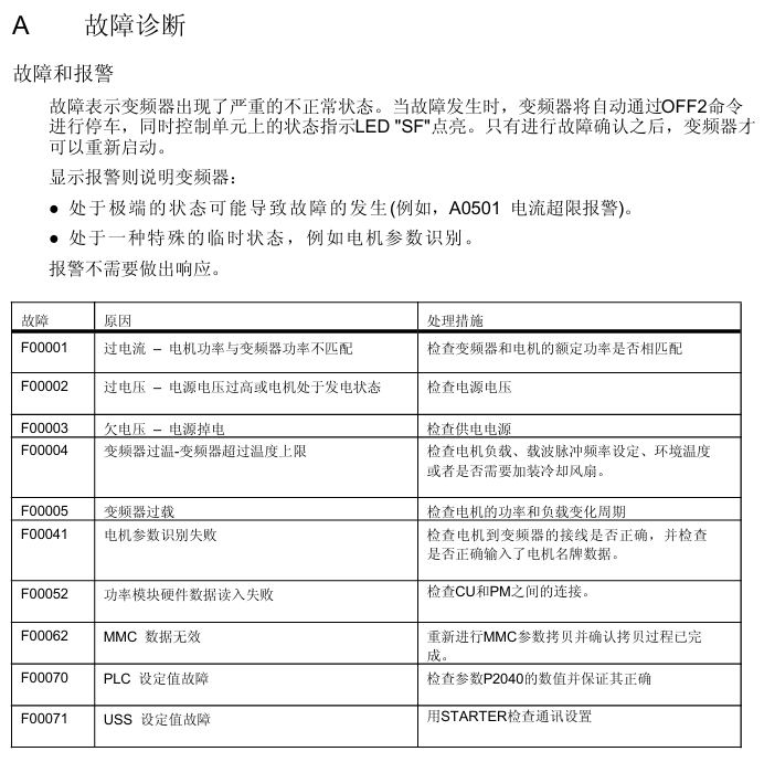
Handling mechanism: When a fault occurs, the frequency converter automatically stops through the OFF2 command, and the red SF (system fault) LED on the control unit lights up; The frequency converter can only be restarted after confirming the fault.
(2) Alarm
Nature: The equipment is in an extreme state (which may cause malfunctions) or a special temporary state (such as motor parameter identification), and does not affect the basic operation of the system.
Processing mechanism: No manual response is required, the alarm status will be automatically eliminated or continuously prompted as the working conditions change.
2. Common faults and their solutions
Fault code, fault cause, handling measures
F00001 overcurrent, motor power does not match frequency converter power. Check if the rated power of the frequency converter and motor are consistent to ensure matching
F00002 overvoltage, high power supply voltage or motor in power generation state. Check if the input power supply voltage is within the rated range and investigate the cause of the motor's power generation condition
F00003 undervoltage, power failure or low voltage. Check the stability of the power supply and troubleshoot power outages or voltage drops
F00004 frequency converter overheating, exceeding the upper temperature limit, check whether the motor load is overloaded, whether the carrier pulse frequency is set reasonably, whether the ambient temperature is too high, and install a cooling fan if necessary
F00005 frequency converter overload check whether the motor power matches, whether the load change cycle is reasonable, and optimize the load working conditions
F00041 motor parameter recognition failed. Check if the wiring from the motor to the frequency converter is correct and confirm if the motor nameplate data is accurately inputted
F00052 Power module hardware data read failure. Check if the connection between the control unit (CU) and the power module (PM) is secure and in good contact
F00062 MMC data is invalid. Copy MMC parameters again to ensure a complete and uninterrupted copying process
F00070 PLC setting value fault check parameter P2040 numerical setting to ensure that the setting value is correct and effective
F00071 USS setting value fault. Use STARTER software to check if the USS communication settings (such as baud rate, address, etc.) are correct
F00072 USS setting value fault check whether the communication status and parameter configuration of the USS main station are normal
F00090 Encoder Feedback Signal Loss Check if the encoder is securely installed and wired correctly, and re debug the encoder
After replacing the F0395 CU/PM with power on, copying the startup parameters, or confirming if the device replacement process is standardized due to EEPROM read errors, perform parameter copying or debugging again, and troubleshoot EEPROM faults
3. Common alarms and their meanings
Alarm code alarm meaning
The parameters and configuration settings of A0700 PROFIBUS master station are invalid, and the PROFIBUS configuration needs to be modified
A0702 PROFIBUS connection interrupted, check the connectors, cables, and PROFIBUS master station
A0703 cannot obtain the set value from the PROFIBUS master station (control word=0) or the set value is invalid. Check the output of the master station set value
At least one intermediate node of A0704 configuration is not working or has malfunctioned
A0705 cannot obtain actual value from frequency converter (no frequency converter fault)
A0706 r2041 No diagnostic information, there may be a PROFIBUS DP software malfunction
A0710 frequency converter detected a PROFIBUS communication fault, and the communication port on the control unit may have malfunctioned
A0711 PROFIBUS parameter is invalid, check P0918 address settings and parameter P2041
4. LED status indication diagnosis
The control unit displays the device status through two LED indicator lights, with the following specific meanings:
LED name, color, status, meaning
SF (system malfunction): The red lit device indicates a system malfunction related to software and hardware
SF (system fault) red off, no system fault
SF (system fault) flashing red (0.5Hz) fault not confirmed or fault ongoing
RDY (Ready) green light indicates that the frequency converter is ready to start running (does not mean it is currently running)
RDY (Ready) green goes out. The frequency converter is not ready (such as not powered on, faults not resolved, etc.)
RDY (Ready) green flashing (0.5Hz) device in standby or transition state
- YOKOGAWA
- Reliance
- ADVANCED
- SEW
- ProSoft
- WATLOW
- Kongsberg
- FANUC
- VSD
- DCS
- PLC
- man-machine
- Covid-19
- Energy and Gender
- Energy Access
- Renewable Integration
- Energy Subsidies
- Energy and Water
- Net zero emission
- Energy Security
- Critical Minerals
- A-B
- petroleum
- Mine scale
- Sewage treatment
- cement
- architecture
- Industrial information
- New energy
- Automobile market
- electricity
- Construction site
- HIMA
- ABB
- Rockwell
- Schneider Modicon
- Siemens
- xYCOM
- Yaskawa
- Woodward
- BOSCH Rexroth
- MOOG
- General Electric
- American NI
- Rolls-Royce
- CTI
- Honeywell
- EMERSON
- MAN
- GE
- TRICONEX
- Control Wave
- ALSTOM
- AMAT
- STUDER
- KONGSBERG
- MOTOROLA
- DANAHER MOTION
- Bentley
- Galil
- EATON
- MOLEX
- Triconex
- DEIF
- B&W
- ZYGO
- Aerotech
- DANFOSS
- KOLLMORGEN
- Beijer
- Endress+Hauser
- schneider
- Foxboro
- KB
- REXROTH
- YAMAHA
- Johnson
- Westinghouse
- WAGO
- TOSHIBA
- TEKTRONIX
- BENDER
- BMCM
- SMC
- HITACHI
- HIRSCHMANN
- XP POWER
- Baldor
- Meggitt
- SHINKAWA
- Other Brands
- UniOP
- KUKA
- IBA
- Beckhoff
-
LTI SC52.0040.0012.0000.0 - Servo Drive
-
Lti SC52.0040.0012.0000.0 - Servo Drive
-
Milton Industries LTI Tool By Milton LT1240 - 1/2" Drive Lugnut Remover
-
LTi Drives SO84.200.P030.0000.0-W - Servo Spindle Drive
-
LTI DRIVES LSP08-035-320-30-B0R1PY170 - Servo Motor
-
LTI DRIVES SE84.200.SC00.0001.0-W - Servo Drive
-
Lust CDE34.005.W2.2 - Lti Drives Controller
-
LTi SO84.012.0030.0011.2 - ServoOne Servo Drive
-
LTi Drives SO CM-P.0010.11.00.0 - Servo Drive Controller
-
LTi CDE34.017.W3.0 - Servo Drive
-
LTI Drives CDB32.004, C2.0,SH - Positioning Controller
-
LUST CM-CAN1 - LTi DRIVES Communication Module
-
LTi SO84.012.1030.0000.2 - Servo Drive
-
LTI MOOG CDE54.044 - PITCHMASTER FREQUENCY CONVERTER 181-01019
-
MOOG LTI 181-01019 CDE54.044 - PITCHMASTER FREQUENCY CONVERTER
-
Lust LTi Drives CDE34.010,D2.0 - Servo Drive Controller
-
LTI SO84.032.0003.0101.2 - Servo Drive
-
Seagate 9CC132-302 Harris LTI-CS IRT-34-0021-01 - Hard Drive 160GB
-
LTI SO84.032.0003.0001.2 - Servo Drive
-
LTI SO24.007.0070.0000.1 - SERVO CONTROLLER
-
LTi drive CDA32.003.C3.0.H05-01.PC1 - Servo Drive
-
LTI SO84.016.0030.0000.2 - SERVO CONTROLLER
-
LUST LTI CD A34.008,W1.4, BR - SERVO DRIVE
-
MOOG LTI 181-01019 CDE54.044 - PITCHMASTER FREQUENCY CONVERTER
-
LTI MOOG 181-01019 - PITCH Master Servo Drive CDE54.044
-
LTI SERVO ONE SO84.045.0030.0001.2-W - Drive
-
LUST LTi SO84.032.0040.0000.2 - SERVO ONE DRIVE
-
LTi Drives LSH-074-2-30-3 20/T1,G6.1M - SERVO MOTOR
-
LTI SO84.016.0000.0101.2 - servo drive
-
LTI SA54.0550.0033.0000.0 - Servo Drive
-
LTI SA54.0550.0033.0000.0 - Servo Drive
-
LTI LT 4850 - 3/8" Drive 3-Pc Twist Socket Transmission Drain Plug Removal System
-
LTI Tools LT4400-30 Lock Technology - 3/4" Twist Socket 1/2" Drive Lugnut Remover
-
LTI Tools LT-1400C - 1/2 Drive Wheel Torque Extension Tool
-
LTI Tools LT1250 - 1/2" Drive Dual Sided Socket Lug Nut Remover Tool
-
LTI SO84.032.0003.0101.2 - Servo Drive
-
LTI MOOG 181-01019 - PITCH Master Servo Drive CDE54.044
-
MOOG LTI 181-01019 CDE54.044 - PITCHMASTER FREQUENCY CONVERTER
-
MOOG LTI 181-01019 CDE54.044 - PITCHMASTER FREQUENCY CONVERTER
-
MOOG LTI 181-01019 CDE54.044 - PITCHMASTER FREQUENCY CONVERTER
-
LTI SA54.0550.0033.0000.0 - Servo Drive
-
LTI Tools LT-4800 - 7 Piece Twist Socket 3/8" Drive Oil Drain Plug Removal Set
-
LTI SA54.0550.0033.0000.0 - Servo Drive
-
LTI Drive SO24.007.00300000.0 - Servo Drive
-
LTI TOOLS LTI 1400-I - Drive Wheel Torque Extension
-
LTI Tools LT4400-3 - 3/4" 19mm Twist Socket 1/2" Drive Lugnut
-
LTI TOOLS LTI 1400-BB - Drive Wheel Torque Extension
-
LTI SO84.032.0003.0101.2 - Servo Drive
-
LTI Tools LT-4512 - 3/8" Drive 12mm Twist Socket
-
LTI MOTION Luster SO84.032.0003.0001.2 - Servo Drive
-
LTI Tool By Milton LT1600P - 1" Drive Torx Stick
-
LTI Lust VF1424L,HF,OP2,S56 - Variable Frequency Drive
-
LUST CDA32.004,C1.4,H08,B0 - SERVO DFRIVE CM-CAN1 Module
-
LTI SO84.045.0002.0001.2-W - Drive
-
LTI Lust VF1404M,C9,PT1,BR1 - Inverter Type VF1404M
-
LTI SA54.0550.0033.0000.0 - Servo Drive
-
LTI Tools LT-1400C - 1/2" Drive Wheel Torque Extension
-
Lust LTI DRiVES CDA32.006, C3.0, H09 - Variateur De Fr茅quence Frequency Inverter
-
LTI MOOG CDE54.044 - PITCH master SERVO DRIVE
-
LTI MOOG CDE54.044 - PITCH master SERVO DRIVE
-
LTI SO84.143.0020.0101.2-W - servo drive
-
LTI MOTION SC34.0200.0011.0000.0 - Servo drives
-
LTI SO84.032.0003.0001.2 - Servo Drive
-
LTI DRIVES GmbH MS100 - Assembly Set Mounting Kit
-
LTI SO84.032.0003.0001.2 - Servo Drive
-
LTI SO84.032.0003.0001.2 - Servo Drive
-
LTI MOTION SO84.032.0003.0101.2 - servo drive
-
LTI SO84.032.0003.0101.2 - Servo Drive
-
LTI MOOG CDE54.044 - PITCH master SERVO DRIVE
-
LTI MOTION CDE32.004.C2.4 - Servo drives
-
LTI CDD34.032锛學x.x锛孊R锛孭C1 - Servo Drive
-
Lust LTI DRiVES CDA32.006, C3.0, H09 - Inversor De Frecuencia Frequency Inverter
-
Lust SO84.008.0030.1000.0 - Servo One LTi Drive
-
LTI MOTION SO84.032.0003.0101.2 - Servo drives
-
LUST LTi CDA32.004,C1.4 - SERVO DRIVE
-
LTI MOOG CDE54.044 - PITCH Master SERVO DRIVE
-
LTI KEBA CDB32.004 C2.7, SH - PN: 08673530 Frequency Inverter
-
LTI Tools LT-1400C - 1/2" Drive Wheel Torque Extension
-
LTI LT1400-E - 1/2" Drive Wheel Torque Extension
-
LTI MOOG 181-01019 - PITCH master SERVO DRIVE CDE54.044
-
LTI LSN-097-0510-30-560/T1 - Actuator Motor
-
LTI Tools LT 4800 - 7 Piece 3/8" Drive Twist Socket Oil Drain Plug Removal System
-
LTI DRIVES GmbH MS100 - MONTAGESET Assembly Set Mounting Kit
-
Lti SC52.0040.0012.0000.0 - Servo Drive
-
LTI DRIVES GmbH MS100 - Juego De Montaje Assembly Set Mounting Kit
-
LTi DSM4-14.2-21R83-200 - Drives servomoteur Servo Motor
-
MOOG CDE 54.044.GDA - Pitch Master Industrielle Turbine Lti Drive
-
LTI SO24.004.0030.1000.0 - Servo Drive Controller
-
Lti MOOG CDE54.044 - Pitch Master Servo Drive
-
Lust LTI DRiVES CDA32.006, C3.0, H09 - Inverter
-
LTI MOTION GMBH CDB34.006,W3.0,PC1,H39 - Frequency inverter
-
LTI SO84.032.0003.0001.2 - Servo Drive
-
MOOG CDE 54.044.D - Pitch Master Industrielle Turbine Lti Drive
-
LTI TOOLS LT-1460 - 1/2" DRIVE WHEEL TORQUE EXTENSION KIT 5 PIECE SET
-
Lust Cdb32.003, C2.4 - Lti Drives Servoregulador Frecuencia Servo Controller Inverter
-
Lust LTI DRIVES CDA32.006, C3.0, H09 - Frequency Inverter
-
Lust Lti SO82.004.0030.0000.2 - Servo Drive
-
LTI MOTION SC34.0200.0011.0000.0-SL - Servo drives
-
LTI MOTION SA54.0075.0033.0000.0 - Servo drives
-
LTI MOTION SC32.0075.1011.0000.0 - Servo drives
-
Lust Cdb32.003, C2.4 - Lti Drives Servo Controller Frequency Inverter
-
LTI MOOG CDE54.044 - PITCH master SERVO DRIVE
-
Lust Lti Cde34.006,W2.0,Br - Servo Drive
-
Lust LTi MOTION CDE34.044,W2.4,H13 - Servo Drive
-
Lust LTi Drives Cde32.008, W2.2.br - Positionierregler Posici贸n Mando Positioning Controller
-
LTI MOOG CDE54.044 - PITCH master SERVO DRIVE
-
LUST Antriebstechnik B-DS 125.1 - LTi DRiVES Accessories Drive Component
-
LTi LSMM13-100-4N-001 - servo motor
-
Lti CDA32.004 C1.4, H08, B0 - PN: 3084456 Frequency Inverter
-
LTI MOTION CDE34.006.WXX.PC1 - Servo drives
-
LTI MOTION SO24.007.0030.1000.0 - Servo drives
-
Lust CDD34.005.C2.1 - LTI Drive
-
Lti SC52.0040.0012.0000.0 - Servo Drive
-
LTI Tools LT4400-30 - 1/2" Drive 19mm 3/4" Twist Socket
-
Lust LTi Drives Cde32.008, W2.2.br - Positionierregler Posici贸n Mando Positioning Controller
-
LTI MOOG CDE54.044 - PITCH master SERVO DRIVE
-
LUST Antriebstechnik B-DS 125.1 - LTi DRiVES Accessories Drive Component
-
LTI DRIVES GmbH MS100 - MONTAGESET Assembly Set Mounting Kit
-
Lust LTi SO84.032.0043.0000.2 - Servo one Drive
-
LUST LTi Drives CM-CAN1 - Modulo Di Comunicazione Communication Module
-
LTI drive CDF 30.008.C3.6 - Servo Drive
-
LTI MOOG 181-01019 - PITCH master SERVO DRIVE
-
LTI CDB34.014,W2.4,BR,SH - Servo Driver
-
Lti SC52.0040.0012.0000.0 - Servo Drive
-
LTi Drive CDF30.002 - Power Supply Fuse
-
LTI Tools LT-4621-D - Deep Well Twist Socket 3/8" Drive 1/2"
-
LTI MOOG PITCH master CDE54.044 - SERVO DRIVE Frequency Converter
-
LTI SO84.076.S030.0001.2-W - Servo One Drive

K-JIANG

Add: Jimei North Road, Jimei District, Xiamen, Fujian, China
Tell:+86-15305925923