

K-WANG


SIEMENS SIMATIC HMI Basic Panels Operating Manual
Today, visualization is part of the standard repertoire for most machines. The cost factor plays a crucial role in this case, especially for small machines and simple applications. HMI devices with basic functions are often fully sufficient for simple applications.
This is exactly the demand that we intend to meet – with our new SIMATIC HMI Basic Panels. By concentrating on the essentials, the Basic Panels offer exactly those basic features that are demanded – at the right price. A perfect cost-to-performance ratio.
Like all devices in our product catalog, the new Basic Panels offer proven SIMATIC quality and – regardless of their display dimensions – many software functions as standard: for example, an alarm system, recipe management, trend functionality and language switching.
Users therefore profit from the advantages of visualization, such as improved process quality, even with simple applications.
SIEMENS SIMATIC HMI Basic Panels Operating Manual
Product Overview
Users therefore profit from the advantages of visualization, such as improved process quality, even with simple applications.
Equipment Overview and Structure
1. Product positioning and core functions
Positioning: Targeting small machines and simple applications, with the design concept of "focusing on core functions", balancing cost and performance, providing cost-effective visual solutions.
Standard features: All devices have SIMATIC quality, regardless of display size, with standard software functions such as alarm system, formula management, trend function, language switching, etc., which can improve the process quality of simple applications.
2. Structural details of each device
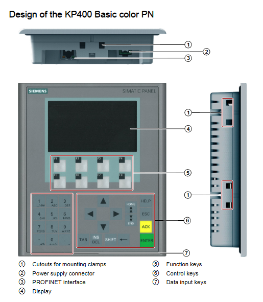
KP300 Basic mono PN: includes power connector, function keys, PROFINET interface, nameplate, display, installation seal, control keys, interface name, installation fixture cut, functional grounding connection, and is a monochrome display keyboard device.
KP400 Basic color PN: Adding data input keys on the basis of KP300, it is a color display keyboard device, which includes function keys such as ACK, TAE, SHIFT, and ENTE, and has an identification bar guiding device.
KTP series (KTP400/600/1000 Basic): All are "touch+function key" combination devices. KTP400/600 supports monochrome/color display, while KTP1000 only displays color. The structure adds a touch screen, and the interface includes PN/DP types. Some models have DIP switches (for RS422/RS485 configuration).
TP1500 Basic color PN: pure touch device, no function keys, only includes PROFINET interface, structure includes fixed components, installation seals, etc., display size is 15 inches.
3. Product packaging and accessories
Package contents:
Required components: HMI device (1 unit), quick installation guide (1 copy), installation seal (1 piece, KTP600 Basic needs to be installed separately, other devices are pre installed), power terminal (1 piece).
Installation fixtures: Configure according to equipment type differences, such as KP300 Basic with 4 plastic fixtures, KP400 Basic with 7 plastic fixtures, KTP400 Basic mono PN with 5 aluminum fixtures, etc.
Core accessory type:
Converter/adapter/connector: such as RS422 to RS232 converter (order number 6AV6671-8XE00-0AX0), PC/PPI cable (6ES7 901-3CB30-0XA0), USB/PPI cable (6ES7 901-3DB30-0XA0), PROFINET RJ45 connector (6GK1901-1BB10-2AA0), etc., clarify the purpose and adaptation scenarios of each accessory.
Clamping frame: such as the clamping frame for 10 "/12" touch devices (6AV6 671-8XS00-0AX0), used for reinforcement when the cutting material for KTP1000 Basic installation is insufficient.
Protective film: Classified by equipment size, such as 4-inch protective film (for KTP400 Basic mono PN, 6AV6 671-2EC00-0AX0), 15 inch protective film (for TP1500 Basic, 6AV6 574-1AD00-4EX0).
Service package: such as 20 plastic fixture sets (6AV6671-8KX00-0AX2), 10 power terminal sets (6AV6671-8XA00-0AX0).
Preparation before equipment installation
1. Packaging inspection and document storage
Inspection requirements: After receiving the equipment, check whether the packaging is damaged during transportation and confirm that the contents are intact (refer to the "Product Packaging" list); If damaged components are found, installation is not allowed and Siemens representatives should be contacted.
Document management: It is necessary to properly keep the accompanying documents, which are part of the equipment and require guidance from the documents for subsequent debugging and maintenance.
2. Confirmation of environmental conditions
Standard reference: It is necessary to familiarize oneself with the standards, certifications, EMC parameters, and technical specifications of the equipment in advance. Relevant information is distributed in "Certificates and approvals", "Electromagnetic compatibility" “Information on insulation tests, protection class and degree of protection”( Sections such as insulation testing, protection level information, and "Power supply".
Mechanical and climatic conditions:
Operating environment: It must comply with the mechanical (vibration, shock) and climatic (temperature, humidity, air pressure) parameters specified in the "Conditions of use", and avoid use in areas with high ionizing radiation, corrosive environments, and strong electromagnetic interference (unless additional measures are taken).
Transportation and storage: It must comply with the IEC 60721-3-3 (3K7 level) storage standard, IEC 60721-3-2 (2K4 level) transportation standard, temperature range -20~+60 ℃, relative humidity 10%~90% (no condensation), and avoid falling (≤ 1m), severe vibration, etc.
3. Installation location selection
Installation posture:
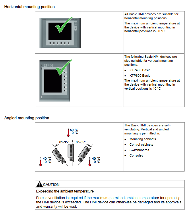
Horizontal installation: All Basic Panels are supported, with a maximum ambient temperature of 50 ℃.
Vertical installation: Only supported by KTP400 Basic and KTP600 Basic, with a maximum ambient temperature of 40 ℃.
Tilt installation: The equipment is self ventilated and can be tilted (0 °~35 °) in control cabinets, distribution boxes, and control consoles, with a temperature range of 0~40 ℃ or 0~50 ℃ (depending on the equipment type).
Temperature warning: If the maximum allowable ambient temperature is exceeded, forced ventilation is required, otherwise the equipment may be damaged and the equipment certification and warranty will be invalidated.
4. Requirements for installation clearance and incision
Gap requirement: To ensure self ventilation of the equipment, a specific gap (unit: mm) needs to be reserved, as follows:
|Device type | x-direction | y-direction | z-direction|
|KP300 Basic|15|40|10|
|KP400 Basic|/|40|10|
|KTP400 Basic|/|40|10|
|KTP600 Basic|15|40|10|
|KTP1000 Basic|15|50|/|
|TP1500 Basic|15|50|10|
Incision requirements:
Material strength: The material in the incision area should be strong enough to ensure the long-lasting and safe installation of the equipment, avoiding material deformation caused by fixture force or equipment operation.
Protection level guarantee: If the protection level needs to reach IP65 or Type 4X/Type 12 (indoor only), the thickness of the cut material should be 2-6mm (KP300 Basic mono PN is 2-4mm); The deviation of the incision plane is ≤ 0.5mm; the surface roughness of the sealing area is ≤ 120 μ m (R120); If the thickness of the incision material is less than 2mm, an additional clamping frame is required for KTP1000 Basic.
Compatibility: The installation slots of Basic Panels are compatible with some older SIMATIC HMI devices, such as KTP400 Basic compatible with TP 177B 4 ", KTP600 Basic compatible with TP 177A, TP 177B 6", etc.
Size parameters: When installed horizontally, KP400 Basic has a cutting size of 135 (w) × 171 (h) mm, KTP1000 Basic has a cutting size of 367 × 289mm, etc; When installed vertically, the cut size of KTP400 Basic is 123mm (specific direction), please refer to the dimension diagram in the document for details.
5. Function key identification
Identification rule: Function keys with no available identification for KP300 Basic; Other devices require printable and writable film as identification strips, with a thickness not exceeding 0.15mm. The use of paper identification strips is prohibited, and direct writing of identification on the keyboard is not allowed.
Identification process:
Edit templates on PC, which can be downloaded from the "CD3 Documents<language> Slides" directory of WinCC/WinCC flexible DVD or Siemens official website.
Print the edited template on the film, and spray a fixed spray film on the identification strip.
Wait for about 5 minutes until the spray is dry and free of stains.
Trim the identification strip and cut its corners into a 45 ° angle for easy insertion.
Insert the identification strip into the guide slot to the end, and the identification strip will extend about 3cm. The template size has been preset, and there is no
Equipment installation process
1. Required tools and accessories
Tools: No. 2 Phillips screwdriver, No. 3 Phillips screwdriver, TX20 Phillips screwdriver, crimping pliers.
Accessories: Installation fixtures for corresponding equipment (aluminum/plastic, quantity according to equipment type), installation seals (if not pre installed).
2. Equipment insertion steps
Seal installation: If the device is not pre installed with a seal, it needs to be inserted into the groove on the back of the front panel of the device to ensure no distortion. Proper installation of the seal is the key to achieving IP65 protection level.
Device embedding: Insert the device into the installation slot from the front, taking care to avoid protruding identification strips getting caught between the slot and the device.
3. Fixture fixing method
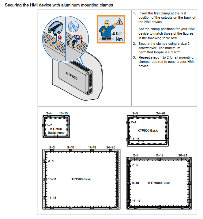
Aluminum fixture fixation (applicable to KTP400 Basic mono, KTP600 Basic, KTP1000 Basic, TP1500 Basic):
Insert the first fixture into the first position of the back cut of the equipment, and the fixture position should match the corresponding diagram of the equipment in the document.
Tighten the fixture with a No.2 screwdriver, with a maximum torque of 0.2N · m.
Repeat steps 1-2 to install all required fixtures.
Plastic fixture fixation (applicable to KP300 Basic, KP400 Basic, KTP400 Basic colors):
If the fixture needs to be installed separately, first insert the set screw and turn it several times, then place the fixture in the corresponding position of the equipment.
Install all plastic fixtures according to the required quantity of equipment, ensuring that the equipment is securely fixed.
Equipment Connection Specification
1. Preparation before connection
Tools and accessories: Prepare a No. 2 Phillips screwdriver, a No. 3 Phillips screwdriver, a TX20 Phillips screwdriver, a crimping tool, power terminals, and a 24VDC power supply (current must meet equipment specifications, refer to the "Power supply" section).
Connection sequence: Strictly follow the order of "equipotential connection → power connection → configuration PC connection → PLC connection", do not reverse, and provide sufficient strain relief for all cables to avoid contact breakage or wire detachment.
2. Equipotential connection
Connection necessity: There may be potential differences between equipment components separated by space. If the shielding layer of the data cable is grounded at both ends and connected to different equipment components, it may generate large balanced currents and damage the interface; Systems powered by different power sources may also generate potential differences, and the risk needs to be reduced through equipotential connections.
Connection requirements:
Conductor requirements: The equipotential bonding conductor should be made of copper or galvanized steel, with a cross-sectional area of not less than 16mm ² (to ensure maximum balanced current), and should establish a large surface area contact with the grounding/protective conductor to prevent corrosion.
Shielding treatment: The shielding layer of the data cable needs to be clamped flat and clamped onto the equipotential rail near the HMI device using a suitable cable clamp.
Wiring requirements: The equipotential bonding conductor and data cable should be laid in parallel with minimal gap.
Prohibited items: The cable shielding layer shall not be used for equipotential connection. MPI and PROFIBUS DP networks must use cables with sufficient cross-section, otherwise it may damage the interface module.
Operation steps:
Connect the functional grounding of the HMI device with a grounding wire with a cross-sectional area of 4mm ².
Connect the grounding wire to the equipotential rail.
3. Power connection
Cable requirement: Use power cables with a maximum cross-sectional area of 1.5mm ².
Cable handling:
Strip the ends of the two power cables by 6mm.
Install cable conduit at the exposed end of the cable.
Secure the cable conduit at the end of the cable using crimping pliers.
Connection steps:
Insert two power cables into the power terminals using a Phillips screwdriver and secure them in place.
Connect the HMI device to the power terminal and ensure correct polarity (distinguish between+24VDC and GND).
Turn off the power supply.
Insert the remaining two cable ends into the power terminal and secure them, then confirm the polarity again.
Safety warning: Only 24VDC power supply can be used, and the power supply current must comply with the equipment specifications (refer to the "Specifications" section). Incorrect specifications of power supply may cause equipment damage.
4. Programming equipment and configuration PC connection
Programming Device Connection (Basic Panel DP):
Function: Can be used for project transfer and device image transfer, but cannot be used to restore factory settings.
Step: Turn off the HMI device, confirm that the DIP switch on the back of the device is in the designated position, and connect the RS485 PROFIBUS connector to the device.
Configure PC connection:
Function: Supports project transfer, device image transfer, and factory reset.
Basic Panel DP Connection: Use PC/PPI cable or USB/PPI cable for connection, and configure the DIP switch of the cable to set the transmission rate (such as 115.2kbps corresponding to DIP1=1, DIP2=1, DIP3=0). If the connection is lost during operating system updates, the bit rate needs to be reduced; When using high bit rates, PC/PPI cable version 3 or above is required (version number printed on the cable, such as "E stand 3").
Basic Panel PN Connection: Use the "IE FC RJ45 Plug 2x2" RJ45 plug (order number 6GK1901-1BB10-2AA0) and connect it with a standard CAT-5 Ethernet cable; Attention should be paid to Ethernet data network security, and users need to ensure network security themselves to avoid risks such as device overload.
5. PLC connection
Connection prerequisite: The HMI device must have an installed operating system and executable projects.
Connection specification: When wiring, the data line should be parallel to the equipotential connecting conductor, and the shielding layer of the data line should be grounded.
Basic Panel DP Connection:
Direct connection: Connect SIMATIC S7-200, S7-300/400, S7-1200 through RS422/RS485 interface.
Converter connection: Connect third-party PLCs such as Modicon Modbus and Allen Bradley DF1 through the converter in the accessory (such as RS422 to RS232).
Interface configuration: There is a DIP switch on the back of the device for RS422/RS485 interface configuration. The factory default setting is to communicate with SIMATIC PLC through RS485, which needs to be adjusted according to the DIP switch setting diagram on the back of the device (such as RTS signal position).
Basic Panel PN Connection:
Connecting devices: Connect SIMATIC S7-200, S7-300/400, and S7-1200 with PROFINET interface via PROFINET/LAN.
Security and Accessories: PN interface requirements for PC connection with the same configuration require the use of designated RJ45 plugs to ensure network security.
Equipment start stop and testing
1. Device startup and Loader operation
Startup process: After turning on the power, the operating system starts and then opens the Loader.
Loader operation method:
Touch device: Operate the Loader through touch screen buttons.
Keyboard device: Navigate menus through cursor keys, execute menu commands or enter submenus with the<ENTER>key.
Loader core functions:
Transfer: Click the "Transfer" button or execute the "Transfer" menu command to set the device to "Transfer Mode". At least one data channel must be enabled to activate it.
Start: Click the "Start" button or execute the "Start" menu command to start the project on the device; If not operated, the project will automatically start after a delay.
Control Panel: Click the "Control Panel" button or execute the "Info/Settings" menu command to open the device control panel, where you can modify transmission settings and other parameters.
2. Device shutdown
Closing steps:
Close all active projects on the device.
Choose one of the following ways to turn off the device: turn off the power supply; Remove the power terminal from the device.
3. Cable fixation
Fixed requirements: Some equipment (KTP1000 Basic DP/PN, TP1500 Basic) have fixed components on the back, and after power testing, cable ties are needed to fix the connected cables to the components and provide strain relief.
Special equipment: KP400 Basic color PN has an opening on the back that can be inserted into two cable ties to secure the power cord and LAN cable separately.
Equipment Operation Guide
1. Touch device operation (KTP series TP1500 Basic)
Basic operating principles:
Touch mode: The touch screen can only be operated with fingers or a stylus, sharp objects may damage the plastic surface; Only one operating element can be touched at a time to avoid triggering unexpected actions.
Visual feedback: After the device detects the touch operation element, it will provide visual feedback, but the feedback only indicates that the device recognizes the operation and does not represent that the PLC has executed the corresponding action.
Operating element type:
Button: divided into "not touched" and "touched" states; The invisible button has no focus indication or visual feedback by default when selected, and can also be configured to display contours when touched (until other components are selected).
I/O field: After touch, the on-screen keyboard will be displayed (such as when entering a password), and the numeric or alphanumeric keyboard will be displayed according to the device and operating component configuration. After input is completed, the keyboard will automatically hide.
Function key operation:
Function allocation: It can be set as a global function (triggering the same action regardless of the current screen, such as activating the screen or closing the alarm window) or a local function (screen specific, only valid on the current screen). Function keys within the same screen can only be assigned one function, with local functions taking priority over global functions.
Screen keyboard function: All touch devices' screen keyboards include keys such as cursor left movement, cursor right movement, character deletion, cancel input, confirm input, and display information text (only when configuring information text for operating components).
Differences in data input among different devices:
KTP400 Basic: Due to the small display screen and special keyboard and input logic, the keyboard is divided into four views (A-M letters, N-Z letters, numbers, and special characters), which can be switched through the fourth row button; When entering letters, use the<Shift>key to switch between uppercase and lowercase. After entering, press<Return>to confirm or<ESC>to cancel. Additionally, PLC task 51 "Select Screen" is invalid when the keyboard is turned on; The keyboard layout is single language, and language switching within the project does not affect the layout.
KTP600/1000 Basic, TP1500 Basic: Single language layout with alphanumeric keyboard, language switching does not affect the layout; When entering letters, use the<Shift>key to switch between uppercase and lowercase, and when entering numbers, you can operate through the corresponding view; After entering, press<Return>to confirm or<ESC>to cancel. PLC task 51 "Select Screen" is invalid when the keyboard is opened.
Numerical input rules:
Limit check: Tags can set limits, and input exceeding limits will be rejected. If an alarm view is configured, a system event will be triggered and the original value will be displayed.
Decimal processing: Configuration engineers can define the number of decimal places in numerical text boxes. Any decimal places exceeding the limit will be ignored when entering, and unused decimal places will be filled with "0".
2. Keyboard device operation (KP300/400 Basic)
KP300 Basic Operation:
System key types: including control keys (confirm/activate, cancel/help, alarm confirm, delete, help, case switch, TAB key) and function keys with alphanumeric keys.
Control key functions: For example, the confirm key is used to execute menu commands, the cancel key is used to close help and return to the previous view, and the alarm confirm key is used to confirm the current display/selection of alarms or all alarms in the alarm group.
Function key operation: Global/local functions can be set (same as touch devices). When entering on the keyboard, the allocation of function keys becomes invalid, and integrated alphanumeric keys are required to input data.
Data input logic: Function keys are designed according to the logic of the phone keyboard, with each key corresponding to multiple letters, numbers, and special characters (optional). When entering, a menu is displayed, and pressing the key once switches one character (loop); Automatically activate numeric assignment when entering numerical values, activate letter assignment when entering alphanumeric values, and activate A-F letter and numeric assignment when entering hexadecimal values; Function key allocation is invalid in editing mode, displaying the prompt 'Function key disabled'.
Menu and item operations:
Menu navigation: Use the cursor keys to navigate within the menu,<ENTER>execute the command to enter the next level menu; When the menu contains a text box, use the function keys to enter values. When it contains a list, use<ENTER>to activate the list. Use the cursor keys to select an item, and<ENTER>to execute the item; After entering the value, press<ENTER>to apply,<ESC>to cancel or return to the previous menu.
Project operation: Use the<TAB>key to navigate the operating components in the configuration order, or use the cursor keys to freely navigate; Activate the selected component and enter values or select list entries as required; <ENTER>Apply changes,<ESC>Cancel changes.
KP400 Basic Operation:
Key assignment: Data input keys have fixed alphanumeric assignments, such as key 1 corresponding to ".<space>_ @ #?!":; () € § ^~° {} "| 1", key 2 corresponding to "ABC Äނ 2", etc.
General functions: Functions can be triggered by a single key or a combination of keys (holding down the first key and then pressing the second key), such as switching case, deleting characters on the left/right side of the cursor, navigating operating components in TAB order, inserting spaces, displaying help, etc.
Control panel and project operation: When operating the control panel, you can switch between tabs, position the cursor, and activate components by direction; During project operation, it is possible to confirm the current displayed alarm/alarm group alarm and the configuration information text of the calling operation component.
Function key operation: Same as KP300 Basic, global/local functions can be set, with local functions having higher priority.
Data input: Similar to a mobile phone keyboard, long keys automatically insert numbers; The cursor should be located within the text box, press the corresponding key until the desired character is selected, use the<a/A>key to switch case, use the cursor key to navigate the string, press<ENTER>in the control panel to close the dialog box or<TAB>to navigate to the next component, and press<ENTER>in the project to apply input.
- YOKOGAWA
- Reliance
- ADVANCED
- SEW
- ProSoft
- WATLOW
- Kongsberg
- FANUC
- VSD
- DCS
- PLC
- man-machine
- Covid-19
- Energy and Gender
- Energy Access
- Renewable Integration
- Energy Subsidies
- Energy and Water
- Net zero emission
- Energy Security
- Critical Minerals
- A-B
- petroleum
- Mine scale
- Sewage treatment
- cement
- architecture
- Industrial information
- New energy
- Automobile market
- electricity
- Construction site
- HIMA
- ABB
- Rockwell
- Schneider Modicon
- Siemens
- xYCOM
- Yaskawa
- Woodward
- BOSCH Rexroth
- MOOG
- General Electric
- American NI
- Rolls-Royce
- CTI
- Honeywell
- EMERSON
- MAN
- GE
- TRICONEX
- Control Wave
- ALSTOM
- AMAT
- STUDER
- KONGSBERG
- MOTOROLA
- DANAHER MOTION
- Bentley
- Galil
- EATON
- MOLEX
- Triconex
- DEIF
- B&W
- ZYGO
- Aerotech
- DANFOSS
- KOLLMORGEN
- Beijer
- Endress+Hauser
- schneider
- Foxboro
- KB
- REXROTH
- YAMAHA
- Johnson
- Westinghouse
- WAGO
- TOSHIBA
- TEKTRONIX
- BENDER
- BMCM
- SMC
- HITACHI
- HIRSCHMANN
- XP POWER
- Baldor
- Meggitt
- SHINKAWA
- Other Brands
- UniOP
- KUKA
- IBA
- Beckhoff
- ADLINK
-
Siemens 6SL3244-0SA01-1AA0 - SINAMICS G120 Control Unit
-
DANFOSS 175Z2688 - COATEDE CONTROLUNIT VLT5000
-
SIEMENS 6FM1721-3AA20 - Positioning Module
-
REXORTH VTS0605 PVAR S21 - Drive Module
-
BECKHOFF 2915-0000 - Control Module
-
COOPER EATON CGLine 400 40071347901 - CEAG CG Controller
-
SIEMENS 3UF5031-3AN00-1 - SIMOCODE DP Basic Unit
-
SIGMATEK DNC305 05-011-305 - Drive Controller
-
Multivac MV1 10249768 - Control Module
-
SCHNEIDER ELECTRIC MES114 59646 & 59645 - Circuit Breaker Accessory
-
CAMILLE BAUER CAPAX 44-580-0012 - Transmitter
-
HENGSTLER VT360P LS1/TOK - Encoder
-
BURKERT 8792 - 24V DC IP65 / IP67 Positioner
-
SENSOPART V10-OB-A1-W6 - Vision Sensor
-
ALLEN-BRADLEY 1762-L40BXB SER.C REV.J - MicroLogix 1200 Controller
-
HITACHI CPU22-02HC 33025801-2 - CPU Module
-
HITACHI AGH-0 33034810-2 - Control Board
-
PHILIPS AIH110 VER 1.0 - Control Module
-
BAUMULLER DO8000 - Drive Controller
-
B&R PS477 3PS477.9 Rev.C0 - Power Supply
-
ABB ALFA LAVAL 200-CISB - Communication Interface 2 x SatBus
-
Moeller MI4-570-TA1 - HMI Operator Panel
-
ABB ACH550-01-06A9-4+B055 - Variable Frequency Drive
-
ABB TPU2 3HNE00313-1 REV 12 - Teach Pendant Unit
-
Schneider Electric BRS368H130ABA - Stepper Motor
-
Foxboro FCM100E P0972ZA - I/A Series Communication Module
-
Siemens 6ES7 450-1AP00-0AE0 6ES7450-1AP00-0AE0 - Simatic S7 Version:04 Counter Module
-
Schneider Electric ATV320U07N4W - Altivar Machine Drive
-
Priva TouchPoint Flush V06:02 5060002 - Control Panel
-
Lenze ESMD402L4TXA - 4kW SMD Inverter Drive
-
Lenze ESMD402L4TXA - 4kW SMD Inverter Drive
-
Schneider Electric PM210 PM210MG - Powerlogic Power Meter
-
ASCOM U982-DB/1C U982 - Power Supply / Communication Module
-
DYADIC SYSTEMS SCN5-010-050-S03-NA - Servo Cylinder
-
Reliance Electric GMI-S04 - AC/AC CONVERTER 380/400V 50/60Hz 3.9/5.2A
-
Pro-Face GLC150-BG41-XY32KF-24V 3080060 PFXGLC150BDBP - Touch Screen HMI
-
ROFIN RSL TERMINAL V2 0185.01/03 - TERMINAL
-
HONEYWELL R7241E1077 - Burner Control / Amplifier
-
SEW MM22C-503-00 8241201 - 2.2kW Movimot Drive
-
Brand Digital III 50mL - Burette
-
Danfoss 195N0039 VLT2811PS2B20STR1DBF00A00C0 - 2.4kVA VLT Drive
-
SONY LG10-2 EK1 - Digital Gauge Indicator
-
EMERSON SKD3400750 - 7.5kW AC Drive
-
SIEMENS 6AV6 542-0AG10-0AX0 - MULTIPANEL HMI
-
TELEMECANIQUE ATV21HU55N4 - ALTIVAR21 5.5KW Variable Speed Drive
-
MITSUBISHI A985GOT-TBA-EU - GOT900 Touch Screen HMI
-
SCHNEIDER LXM32AD30N4 - Lexium 32 Servo Drive
-
SICK PSR01-1501 M20Z-02550A122 - Safety Laser Scanner
-
GECMA CHALLENGER 15-2-FMO - LITE TOUCH Monitor
-
Uniop EK02 6ZA982 - HMI Operator Panel
-
TELEMECANIQUE ATV18U54M2 - SQUARE D ALTIVAR 18 3kW Drive
-
Schneider Electric ATV312HU75S6 - 7.5kW Altivar 312 Drive
-
Siemens 6GK7243-5DX30-0XE0 6GK7 243-5DX30-0XE0 - Communications Processor
-
Schneider Electric LV432455 VIGI630 - 3POLE Earth Leakage Module
-
Rexroth PSI 6100.750 L1 R911170694-107 - frequency inverter / inverter
-
SWEDISH MICROWAVE AB Ku-Band BDC 138010-45-D0 - Block Downconverter
-
METTLER TOLEDO IND429 IND429-BB30 - Weighing Terminal
-
Siemens 6SL3210-5HE10-4UF0 - Sinamics V90 Servo Drive
-
B&R X20CP0482 Rev.D0 - X20 CPU Module
-
Mitsubishi FR-E720S-110SC-EC FRE720S110SCEC - 31A~11A Drive With Filter
-
ABB ACH580-01-026A-4 - Variable Frequency Drive
-
Siemens 6SL3210-1KE13-2AP1 - SINAMIC G120CDP 1.1kw Drive
-
Schneider Electric TM250D 4P3D LV431440 - Compact NSX250 Circuit Breaker
-
RELIANCE ELECTRIC GD.722.81.00-A 802288-74C - MAXITRON Servo Control Card
-
Uniop EK02 6ZA982 - HMI Operator Panel
-
Siemens 6SE9113-7JA13 - MICRO MASTER Junior 1.5kW Inverter
-
Mitsubishi FR-E720S-110SC-EC FRE720S110SCEC - 31A~11A Drive with Filter
-
Johnson Controls FEC2621 MS-FEC2621-0 - Field Equipment Controller
-
BENDER IR475LYT-429 - A-ISOMETER Insulation Monitor
-
Berger lahr D550 RS15 22.550-00-30b - Stepper Drive
-
Rexroth PSI 6100.750 L1 R911170694-107 - Frequency Inverter / INVERTER
-
KOYO 205 D2-06B-1 D2-240 H2-ECOM D2-08ND3 F2-08TRS - DIRECT LOGIC PLC WITH MODULE
-
TELEMECANIQUE ATV18U54M2 ATV18U54M - SQUARE D ALTIVAR 18 3kW Drive
-
Lenze 471-E1.D - Board / Controller Speed
-
Mitsubishi FR-A740-00038-EC - Frequency Inverter
-
Johnson Controls IOM3723 MS-IOM3723-0 - Input/Output Module
-
CURTIS 1238-5602 - AC Motor Controller
-
FOXBORO P0912XX REV.A - 220VAC Power Supply
-
Siemens 6SE9113-7JA13 - MICRO MASTER Junior 1.5kW Inverter
-
Mitsubishi FR-A740-00038-EC - Frequency Inverter
-
KOYO 205 D2-06B-1 D2-240 H2-ECOM D2-08ND3 F2-08TRS - DIRECT LOGIC PLC WITH MODULE
-
AUTZ M406D-00101 - Servo Motor
-
Lauer PCS095 PG095.508.BB - Operator Panel
-
ABB SCOP45SB/DX232 - SattCon OP45 SB Operator Panel
-
SEW Eurodrive MCH42A0030-5A3-4-00 MDX60A0030-5A3-4-00 - 4.8kVA Movidrive Inverter
-
BENDER IR475LYT-429 - A-ISOMETER Insulation Monitor
-
Johnson Controls FEC2621 MS-FEC2621-0 - Field Equipment Controller
-
Johnson Controls IOM3723 MS-IOM3723-0 - Input/Output Module
-
Berger lahr D550 RS15 22550-00-30b - Stepper Drive
-
SIEMENS 6FX1120-4BD03 6FX11204BD03 5702049304.00 E-Stand: A - Sinumerik Module
-
Allen-Bradley 1771-NIV B - HIGH RESOLUTION ISOLATED ANALOG SERIES Module
-
HONEYWELL XFC2D06001 - Flow Computer / Controller
-
Contraves Varidyn Compact ADB 380.90M - DC Drive 380v - 400v 90A 50kVA
-
Red Lion Control GEM52000 - Control Module
-
Siemens 6ES5 955-3NC13 - modular power supply TYPE:DIN41752
-
Danfoss ICV50 G20Mn50T / 027H5200 - Valve zaw
-
Eberle PLS508 P-814 / 2X EA-88 / A-812 / MT-81 / S-11 - PLC with Modules
-
Siemens 6ES7 314-6CF01-0AB0 6ES7314-6CF01-0AB0 - SIMATIC CPU314C-2 DP
-
EBERLE EM-525-87 EM52487 - ICE DETECTOR BASE UNIT
-
Telemecanique / Schneider TSXRKZ02 - TSX Micro automation plus 7module
-
B&R 5DLSDL.1001-00 - Display Link Receiver
-
Siemens 6FX1120-4BD03 6FX11204BD03 5702049304.00 E-Stand: A - Sinumerik Module
-
ALLEN-BRADLEY 1771-NIV A - HIGH RESOLUTION ISOLATED ANALOG SERIES Module
-
ALLEN-BRADLEY 1771-NIV B - HIGH RESOLUTION ISOLATED ANALOG SERIES Module
-
Contraves Varidyn Compact ADB 380.90M - DC Drive 380V - 400V 90A 50kVA
-
Contraves Varidyn Compact ADB 380.90M - DC Drive 380V - 400V 90A 50kVA
-
Ropex RES-202 - Resistron Temperature Controller
-
HONEYWELL XFC2D06001 - Flow Computer / Controller
-
Telemechanics ATV452U40 - DIMMER ALTIVAR5 SERIES 452 4kW 5HP Frequency Inverter
-
VEGA VEGAPLUS61 PS61.XXAGPHAMAX - Radar Level Sensor
-
BRANSON ULTRASONIC TRANSDUCER - Ultrasonic Transducer
-
Danfoss ICV50 G20Mn50T / 027H5200 - Valve Valvola Zaw
-
Schneider Electric 2001549/1 GALAXY PW 5102851200 NT07 - panler card
-
REXROTH VT3006-36 A - Proportional Valve Amplifier
-
Allen-Bradley 1746-OBP16 SERIES:C - SLC 500 OUTPUT MODULE
-
SCHNEIDER LXM32MD12N4 - Lexium 32 Servo Drive
-
Schneider Electric ATV630U22N4 - 2.2KW Altivar Process Drive
-
Allen-Bradley 1746-OBP16 SERIES:C - SLC 500 OUTPUT MODULE
-
Vanderlande 0E2550-00002... - Bagtrax Integrated Power Module 400V 32A
-
B&R X20CP0410 Rev.D0 - X20 CPU Module
-
VANDERLANDE 0E2550-00002 02EDD2B0100 - BAGTRAX Integrated Power Module 400V 32A
-
Rexroth R061205010 - Linear Bushing / Bearing
-
INDRAMAT TVM1.2-50-220/300-W0-220/380 - Power Supply Module
-
Vanderlande 0E2550-00002... - Bagtrax Integrated Power Module 400V 32A
-
HOMAG KEB 07F5S1A-YA00 09E5T60-1001 - Combivert Inverter WITH KEYPAID AND FILTER
-
Siemens 3RW3047-1BB14 - Soft Starter
-
Sumitomo AF-500 AF502-A40 - 0.4kW Transistor Inverter
-
Sumitomo AF-500 AF502-A40 - 0.4kW Transistor Inverter

K-JIANG

Add: Jimei North Road, Jimei District, Xiamen, Fujian, China
Tell:+86-15305925923