
K-WANG


GE Fanuc i series control operation panel
GE Fanuc i series control operation panel
Core types of operation panel
The manual includes two types of operation panels: North American type and distributed I/O type, both of which are compatible with i-series CNC. The core parameters are shown in the following table:
Panel type, core model, physical dimensions, key characteristics, certification/adaptation
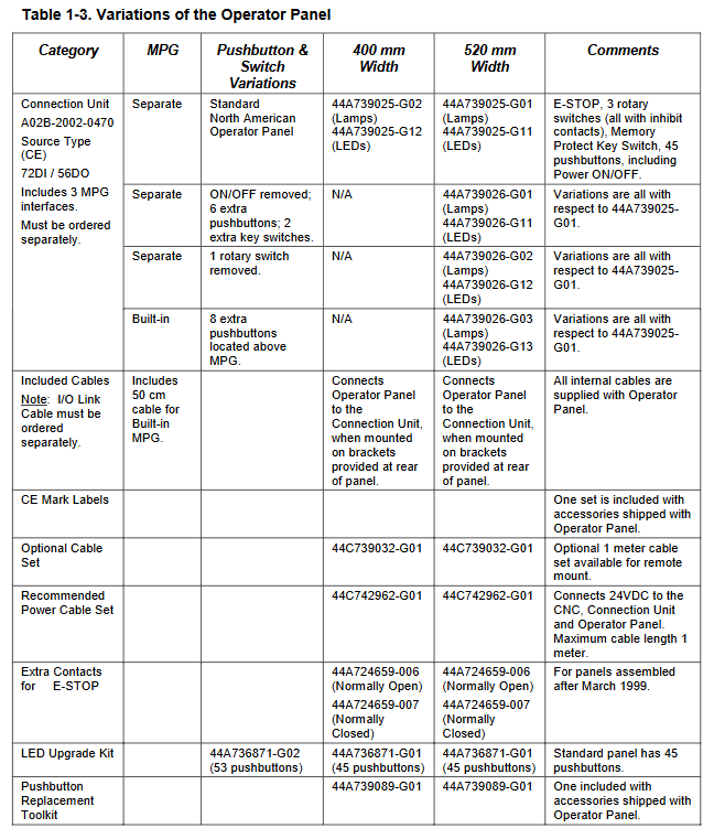
North American model 44A739025 (standard)
44A739026 (customized/with MPG) 520/400mm × 180mm × 90mm (50mm without connecting unit) ① Supports LED/incandescent backlight and cannot be mixed;
② Equipped with emergency stop, rotary switch, and memory protection key;
③ Pre wired, equipped with A20B-2002-0470 mounting bracket;
④ Supports up to 3 MPG UL certifications and CE compliance
Distributed I/O type A02B-0236-C140 (520mm, full keyboard)
A02B-0236-C141 (400mm, small keyboard) 520/400mm × 180mm × 60mm ① membrane keyboard+embedded LED;
② Built in I/O connection unit, supporting 3 MPGs;
③ Magnification switch outputs Gray code (maximum 200%);
④ Lathe (T)/machining center (M), English (R)/symbol (S) version CE certification, compatible with FS0 panel design
Additional features of North American panel: Provides customized services, optional with/without MPG, add/remove buttons, equipped with LED upgrade kit (44A736871-G01/G02), emergency stop button needs to be wired to meet safety requirements.
Connection unit/IO module (three cores)
To adapt to the I/O interaction between the operation panel and CNC, the manual provides three connection units, all of which are source type outputs and electronic fuse protection. They communicate through I/O Link, and the core parameters are shown in the following table (key models/points in bold):
Model I/O point count input type output type MPG support core features
A20B-2002-0470 72DI/56DO 16 ordinary DI+56 matrix DI (8 × 7) 56 24V source type DO up to 3 ① matrix DI needs to be connected in series with diodes to prevent short circuits;
② Exclusive matching for North American panels;
③ DOCOM pin single load ≤ 0.7A
A20B-2002-0520 48DI/32DO 48 channel non matrix DI (fully independent) 32 channel 24V source DO up to 3 channels ① No matrix input, simpler wiring;
② Can be used independently as an I/O module
A20B-2002-0521 48DI/32DO 48 channel non matrix DI (fully independent) 32 channel 24V source type DO Wuwei 0520 without MPG version, all other specifications are completely the same
Common requirement: The 24VDC power supply of the three modules must be connected/disconnected before/at the same time as the CNC is powered on, and disconnected/at the same time after power off, otherwise it will trigger the CNC communication alarm.
Core installation and wiring specifications
(1) Power supply connection (mainly 24VDC ± 10%, 15i special)
16i/18i/21i CNC&Power Mate i D/H: No built-in power supply, requires external 24VDC power supply, recommended cable kit 44C742962-G01, North American panel built-in 24VDC switch (maximum 8A), can synchronously control CNC and peripheral equipment.
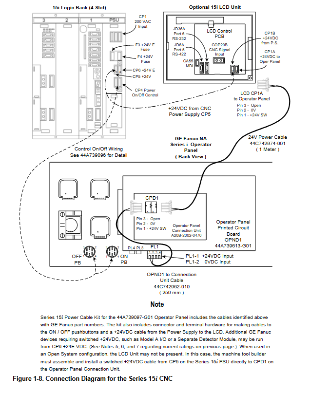
15i CNC: Comes with a 200VAC power supply and can provide 24VDC on its own. It requires a dedicated cable kit 44A739097-G01. The ON/OFF button on the panel is directly connected to the 15i power module without the need for a built-in switch circuit on the panel.
Safety requirements: Reversing the polarity of 24VDC can damage the CNC inverter board. The wiring should be properly grounded and anti-interference. It is recommended to provide separate power supply for external I/O to avoid load interference.
(2) MPG (Manual Pulse Generator) connection
Quantity supported: Three devices with MPG interface (distributed I/O panel, 0470, 0520) all support up to 3 MPGs, and are only available for i-series CNC.
Cable requirements: Recommended cable A66L-00001-0286, with a maximum length of 50m (theoretical 76.75m) for a single MPG, 38.37m for two MPGs, 25.58m for three MPGs, and a voltage drop of ≤ 0.2V.
Signal requirements: The third-party MPG must meet the requirements of HA/HB pulse period ≥ 200 μ s, high level ≥ 3.7V, and low level ≤ 1.5V.
Address occupancy: The MPG interface occupies fixed DI addresses Xm+12~Xm+14, which are directly processed by CNC software and cannot be used for user ladder diagrams.
(3) Emergency stop (ESP) wiring
All emergency stops of panels/modules need to be wired by themselves. The manual provides three wiring schemes, and it is recommended to allocate the emergency stop signal to a fixed DI address of Xm+0.0~Xm+0.7 (0470)/Xm+2.0~Xm+2.7 (distributed I/O type).
Safety requirements: The emergency stop signal is prohibited from being assigned to the matrix DI area and must use normally closed contacts to ensure that the emergency stop is triggered when the wire is disconnected.
(4) Cables and connectors
Special cables: extension cable for North American panel (44A739032-G01, 1m), 15i special power supply line (44C742962-010), MPG special line (A02B-0120-K841/848/847, 7m).
Connector specifications: Recommended power connectors are A02B-0120-K323/K324, I/O ribbon connectors are A02B-0120-K342, and MPG connectors are A02B-0120-K303.
I/O Mapping and Signal Specification
(1) DI/DO mapping rules
Grouping requirements: DI must be grouped by 16 bytes, DO by 8 bytes, as MPG (Xm+12~14) and DO alarm (Xm+15) are fixed addresses and require 16 bytes of DI space.
Address allocation: Distributed I/O panel DO is Yn~Yn+70470 module DO is Yn~Yn+60520/0521 module DO is Yn~Yn+3, the specific address can be customized, but it needs to avoid CNC fixed processing addresses.
Alarm address: The DO overload/overheating alarm is fixedly mapped to Xm+15 and triggered by byte (such as Xm+15.0 corresponding to Yn+0). After triggering, the corresponding DO byte is closed and needs to be restored after troubleshooting.
(2) Signal Electrical Specification
DI signal: Ordinary DI is 24V type, with a capacity of DC30V/16mA, leakage current ≤ 1mA (26.4V), and voltage drop ≤ 2V; matrix DI is 5V type, with a capacity of DC6V/2mA and voltage drop ≤ 0.9V.
DO signal: source type output, maximum load of 200mA per channel (instantaneous), saturation voltage drop ≤ 1V (at 200mA), leakage current ≤ 20 μ A, can be connected in parallel with two channels (maximum 400mA).
Delay time: DI reception delay ≤ 2ms, DO drive delay ≤ 50 μ s, requiring the addition of I/O Link communication delay (≤ 2ms) and ladder diagram scanning period.
Maintenance and troubleshooting
(1) Vulnerable parts and replacement
North American panel renewal parts: button (44A717186-014), ON/OFF button (44A717186-016), rotary switch (44A724658 series), MPG (A860-0202-T001), LED/incandescent light (44A717186-042/051-053).
Tools and kits: Lamp bead disassembly tool (44A739089-G01), LED upgrade kit (44A736871-G01/G02), emergency stop contact accessories (44A724659-006/007).
Jumper setting: The JP1 jumper for North American panels needs to be adjusted according to the backlight type (incandescent bulbs inside the rectangular frame, LEDs outside the frame), and cannot be mixed, otherwise it will cause backlight abnormalities.
(2) Common fault handling
DO alarm: Xm+15, position 1 indicates overload/overheating of the corresponding DO byte. Load short circuit and grounding need to be checked, and the fault will be automatically restored after troubleshooting.
MPG no signal: Check the cable voltage drop (≤ 0.2V), wiring polarity, and CNC address mapping (Xm+12~14) to ensure that the MPG interface is the unit closest to the CNC on the I/O Link.
Communication alarm: Check whether the 24VDC power supply (synchronized with CNC on/off), I/O Link connector (HIROSE F130-20S-CV7 disabled), and panel/module address conflict.
Matrix DI error: If more than 3 buttons are pressed simultaneously, anti misoperation processing should be done through a ladder diagram. The matrix DI needs to be connected in series with diodes, otherwise signal errors will occur.
Environmental and safety regulations
Environmental requirements: Operating temperature of 0-58 ℃, storage/transportation of * * -20~60 ℃ * *, normal humidity of ≤ 75%, short-term (within 1 month) ≤ 95%, vibration ≤ 0.5G, to be used in a closed cabinet, with a temperature rise of ≤ 10 ℃ inside the cabinet.
Safety regulations:
The 24VDC switch power supply of the North American panel has not been cut off by CNC's Control Off logic, please refer to the circuit diagram of the machine tool factory;
Disassembling incandescent lamps requires the use of specialized tools, and the use of conductive tools (such as pointed nose pliers) is prohibited to avoid short circuits triggering I/O errors;
All grounding must comply with FA industry standards, and the wiring must be well treated for anti-interference to avoid electromagnetic interference causing signal abnormalities.
- YOKOGAWA
- Reliance
- ADVANCED
- SEW
- ProSoft
- WATLOW
- Kongsberg
- FANUC
- VSD
- DCS
- PLC
- man-machine
- Covid-19
- Energy and Gender
- Energy Access
- Renewable Integration
- Energy Subsidies
- Energy and Water
- Net zero emission
- Energy Security
- Critical Minerals
- A-B
- petroleum
- Mine scale
- Sewage treatment
- cement
- architecture
- Industrial information
- New energy
- Automobile market
- electricity
- Construction site
- HIMA
- ABB
- Rockwell
- Schneider Modicon
- Siemens
- xYCOM
- Yaskawa
- Woodward
- BOSCH Rexroth
- MOOG
- General Electric
- American NI
- Rolls-Royce
- CTI
- Honeywell
- EMERSON
- MAN
- GE
- TRICONEX
- Control Wave
- ALSTOM
- AMAT
- STUDER
- KONGSBERG
- MOTOROLA
- DANAHER MOTION
- Bentley
- Galil
- EATON
- MOLEX
- Triconex
- DEIF
- B&W
- ZYGO
- Aerotech
- DANFOSS
- KOLLMORGEN
- Beijer
- Endress+Hauser
- schneider
- Foxboro
- KB
- REXROTH
- YAMAHA
- Johnson
- Westinghouse
- WAGO
- TOSHIBA
- TEKTRONIX
- BENDER
- BMCM
- SMC
- HITACHI
- HIRSCHMANN
- XP POWER
- Baldor
- Meggitt
- SHINKAWA
- Other Brands
- UniOP
- KUKA
- IBA
- Beckhoff
- ADLINK
-
ADLINK HPCI-14S12U - Industrial Control Backplane 12PCI Backplane PCI-14S Passive Backplane
-
ADLINK PCIe-GIE74C - image acquisition card 4-CH GigE Vision PoE+ Frame Grabber
-
ADLINK PCI-8164 - control card 4-Axis Advanced Motion Controller Board
-
ADLINK PCIe-U304 - 4 Port USB3 PCIe Frame Grabbers USB Screw Hole Card
-
ADLINK PCI-9112 - Multi-Function Data Acquisition Card DAQ Card
-
ADLINK PCI-7432 - 51-12013-0A50 4-CH Isolated Numérique I/O PCI Cartes Digital I/O Card
-
ADLINK PCA-6106P3-0C1 REV.C1 - backplane 6-Slot Passive Backplane Board
-
ADLINK PCI-7224 - 24-CH Opto-Isolated Digital I/O PCI Board
-
ADLINK CPCI-7433R(G) - Digital Input Board Rear I/O CompactPCI Card
-
ADLINK EBP-13E4 - 51-46703-0A30 Industrial PC Backplane Passive Backplane
-
ADLINK PCIE-HDV62 - Image acquisition card High Definition Video Frame Grabber
-
ADLINK EBP-13E4 - 51-46703-0A30 Industrial Backplane Board Passive Backplane
-
ADLINK 90111-B1 / CPCI-6770 - PCB CPU MODULE CompactPCI Single Board Computer
-
ADLINK PCI-7248 - DATA ACQUISITION PCI CARD 48-CH Parallel Digital I/O Board
-
ADLINK PCI-7230 - 51-12003-0a50 board PCI7230 32-CH Isolated Digital I/O Card
-
ADLINK PCI2A000CB - 51-20000-0B30 Multi-Function DAQ Card Baseboard
-
ADLINK PCI-8134-005 - 4-Axis Motion Controller Card
-
ADLINK PCI-7224 - 24-CH Opto-Isolated Digital I/O PCI Card
-
ADLINK PCI-7434 - 64-CH Isolated Digital Output Card
-
ADLINK PCI-8132 - motion control card 2-Axis Servo & Stepper Controller
-
ADLINK PCI-8134 - Motion Controller PCI Card 4-Axis Controller Board
-
ADLINK PCI-8164 - Motion Control Card 51-12406-0A40 4-Axis Controller
-
ADLINK 51-12001-0C20 - Circuit Board Data Acquisition Interface Module Hardware
-
ADLINK NuPR0-840 - industrial control motherboard Full-Size PICMG CPU Board
-
ADLINK PCI-7444 - 51-12023-0A10 card 128-CH Isolated Digital Output Board
-
ADLINK PCI-1612B - data acquisition card 4-Port RS-232/422/485 Serial Communication Card
-
ADLINK PCI-6208V 009 - 8/16-CH 16-Bit Analog Output Cards PCB-I-E-482=6BX3
-
ADLINK NUPRO-935A/LV - industrial control motherboard Full-Size PICMG SBC Board
-
ADLINK PCI-9114DG - Multi-Function DAQ Card Data Acquisition PCI Card
-
ADLINK ACL-7130 - Data acquisition card Isolated Digital I/O Board
-
ADLINK ABX-6300D-4E1-BP - board ABX6300D4E1BP Video Interface Expansion Card
-
ADLINK CPCI-6940 - CPCI-6940/D1539/M16-0(EA)-000E 6U CompactPCI Processor Board
-
ADLINK NuPRO-760 - industrial control motherboard Half-Size PICMG SBC CPU Board
-
ADLINK IMB-M42H (G)-0020 - industrial control motherboard LGA1155 Micro-ATX Mainboard
-
ADLINK RTV-24 / PCI-MP4S - 51-12519-1C30 4-Channel Real Time Video Capture Board
-
ADLINK PCI-8134 - 4-Axis Servo & Stepper Motion Controller Card
-
ADLINK MXC-6101D - V.PC000.002.ST.00 Box PC Configurable Embedded Computer
-
ADLINK PCI-8134A - 51-12421-0A10 Motion Control Card 4-Axis Controller Card
-
ADLINK DIN-100S / DIN-100SA1 - Technology SCSI-II TB 100-PIN Terminal Block Board
-
ADLINK DIN-812M001 / DIN812M001 - 51-14034-0A1 51140340A1 Terminal Module Breakout Interface
-
ADLINK PCI-8164 - Servo motion control 4-Axis Advanced Controller Card
-
ADLINK PCIe-GIE64 - Acquisition card GigE Vision PoE+ Frame Grabber
-
ADLINK M-302 - Industrial control motherboard ATX PC Board Mainboard
-
ADLINK PCI-8134 - Motion Controller PCI Card 4-Axis Controller Board
-
ADLINK PCI-RTV24 - Image capture card Analog Video Frame Grabber
-
ADLINK PCI-8102 - Motion control card 2-Axis Servo & Stepper Controller Board
-
ADLINK PCI-9112 REV.B1 - Card Multi-Function Data Acquisition Card
-
ADLINK HSI-DI32-M-N / HSL-TB32-M-DIN - Discrete I/O MODULE Distributed Automation Module System
-
ADLINK PCI-7296 - IO card REV.A3 96-CH Parallel Digital I/O Card
-
ADLINK DIN-814P-A4 / 814Y - terminal board Motion Control Interface Block
-
ADLINK DIN-814P-A4 - 51-14056-0A10 PCB-I-E-2736=ZA01 Screw Terminal Board Breakout
-
ADLINK M-322 - motherboard Industrial Control Computer Mainboard
-
ADLINK NUPRO-406 REV:B1 - industrial control motherboard Full-Size PICMG CPU Board
-
ADLINK AMP-204C - card DSP-Based 4-Axis Advanced Pulse-Train Controller
-
ADLINK HPCI14S REV.B1 - industrial computer baseboard 14-Slot Passive Backplane
-
ADLINK PCI-7250 - 8-CH Relay Output & 8-CH Isolated DI PCI Card
-
ADLINK EBP-13E2 - baseplate Passive Backplane Industrial Computer Chassis Board
-
ADLINK LPCI-3488A - PCI-GPIB card 51-12801-0A30 acquisition card IEEE-488 Interface Board
-
ADLINK PCI-6216V-GL - 51-12201-0C30 16-CH 16-Bit Voltage Analog Output Card
-
ADLINK ACL-8454 - 16-CH Isolated Digital I/O & 4-CH Counter Card
-
ADLINK HPCI-9S7U - backplane Passive Backplane Compatible with NuPRO-A301 852 841 842
-
ADLINK DAQ-2010-007 - Simultaneous-Sampling Multi-Function Data Acquisition Card
-
ADLINK MP-C154 - 51-64205-0A10 Motion Control Card 4-Axis Controller Board
-
ADLINK MXE-202/mSSD16B/WiFi-BT - Matrix Rugged I/O Platform Embedded Fanless Computer
-
ADLINK CM-920-R-17 - PC/104-Plus Single Board Computer Module Intel Celeron M
-
ADLINK PCI-7250 NSMP - 8-CH Relay Output & 8-CH Isolated DI Card
-
ADLINK PCI-8164 - 4-Axis Motion Controller PCI Card W/ Cable and Breakout Box
-
ADLINK EMX-100 - Ethernet-based 4-axis Motion Controllers Distributed Motion Module
-
ADLINK PCI-8134A - Press control card 4-Axis Motion Controller Board
-
ADLINK M-845EG REV:3.2 - industrial motherboard Pentium 4 Socket 478 Micro-ATX
-
ADLINK PCI-9114A Rev A2 DG - card High-Resolution Multi-Function Data Acquisition Board
-
ADLINK IEC-915GV - REV 1.1 Industrial motherboard Socket 478 CPU Board
-
ADLINK PCI-9111DG(G) - Data Acquisition Card Multi-Function DAQ Card
-
ADLINK HPCI-15S10 REV:B2 - Industrial computer base plate Passive Backplane Board
-
ADLINK NuPR0-840 / NuPR0-840DV - industrial control motherboard Full-size PICMG CPU Board
-
ADLINK RTV-24 / PCI-MP4S - 51-12519-1C30 4-Channel Real Time Video Capture Board
-
ADLINK NUPRO-780 - industrial control motherboard Pentium III Single Board Computer
-
ADLINK PCI-7296 - 0050 card 96-CH Opto-Isolated Parallel DIO Card Set
-
ADLINK NUPRO-780 - industrial control motherboard PICMG Full-Size SBC
-
ADLINK PCI-7248 - 51-12006-0A3 002 Pci 7248 48-CH Parallel Digital I/O Card
-
ADLINK PCI-7230 - 32-CH Isolated Digital I/O Card
-
ADLINK AMP-204C - motion control card 4-Axis Advanced Controller Board
-
ADLINK PCI-1714UL - Card Ultra High-Speed 4-CH Simultaneous Sampling DAQ
-
ADLINK NuPRO-E330 - industrial computer equipment motherboard PICMG 1.3 SHB SBC
-
ADLINK AMP-204C - DSP-Based 4-Axis Advanced Pulse-Train Motion Controller Module
-
ADLINK PCI-7256 - 001 51-12206-0A2 REV.A2 LPCI-7256 16-CH Latching Relay Output Card
-
ADLINK ND6050 - NUDAM DIGITAL I/0 MODULE Distributed I/O Unit
-
ASEM BM100 - Box PC Embedded Fanless Industrial Computer
-
ADLINK PCI-7250 - PCI Acquisition Card 8-CH Relay Output & Isolated DI Board
-
ADLINK PCI-8164 - Servo motion control 4-Axis Controller Card
-
ADLINK NuPRO-A40H - Industrial Motherboard 51-41807-1A30 OSP LGA1155 H61
-
ADLINK ADMAX X300 SERVER - 51066010-0A30 motherboard Multi-Processor Mainboard
-
ADLINK CMe-GIE62+ - 51-32903-0A30 control card PC/104-Plus GigE Vision Frame Grabber
-
ADLINK NUPRO-780 - industrial control motherboard Full-Size PICMG SBC CPU Board
-
ADLINK ETX-AT-N270-18/GKTEL - 51-71111-OB10 motherboard ETX CPU Module Board
-
ADLINK DIN-812M - interface module Terminal Block Connection Board
-
ADLINK IMB-M42H - industrial control motherboard LGA1155 Micro-ATX Mainboard
-
ADLINK PXIS-2508 - 8-slot 3U PXI Instrument Chassis Power Hardware Assembly
-
ADLINK AMP-208C - Motion Control card DSP-Based 8-Axis Pulse-Train Controller
-
ADLINK PCI-9111 / PCI-9111DG - Multi-Function Data Acquisition Card DAQ Board
-
ADLINK IEEE-488 GPIB card - Bus Interface Controller Communication Board
-
ADLINK RTV-24 - 51-12519-1C30 image acquisition card Video Frame Grabber Card
-
ADLINK TB-24P/24-01 - Board 24 Way Screw Terminal Breakout Board
-
ADLINK HSL-DI16DO16-DB-NN - 51-23015-0A40 Distributed Discrete I/O Module Set
-
ADLINK PCI-7442 - switch quantity card data acquisition card 64-CH Isolated Card
-
ADLINK ACL-7130 REV. B2 - industrial control capture card Isolated Digital I/O PCI Card
-
ADLINK PCI-6S / PCI6S - Backplane 6-Slot Passive Backplane Chassis Board
-
ADLINK ACL-8113A - card Isolated Digital Input Card
-
ADLINK CPCI-6208V-003 - board cPCI CompactPCI 8-CH Analog Output Card
-
ADLINK DIN-100S-01(G) - SCSI 100-Pin Terminal Block Interface Board
-
ADLINK PCI-7433 - Isolated Digital Input Card 64-CH
-
ADLINK PCI-9812 - Synchronous sampling analog input card High-Speed DAQ Board
-
ADLINK PCI-7434 REV.B1 - PLOTECH PCB-I-E-1182=6EX2 64-CH Isolated Digital Output Card
-
ADLINK PCIe-RTV24 - 51-18016-0A20 4-CH Real-Time Video Capture Card PCIe Frame Grabber
-
ADLINK PCI-8144 / PCI-8144N - Motion control card 4-Axis Stepper Motor Controller
-
ADLINK DIN-68S-01 - terminal board 68-Pin Connector Terminal Block
-
ADLINK MP-C154 - Motion control card 4-Axis Advanced Controller Card
-
ADLINK PCI-7248 (G) - Motherboard 48-CH Parallel Digital I/O Card
-
ADLINK MXE-1301(G) - Intel Atom D2550+NM10 MXE 1300 Series 93-4130-0030 Embedded Computer
-
ADLINK PRO-841 Rev 2.0 / PRO-060907000670 - CPU 2.26GHz & RAM Industrial PC Board
-
ADLINK NuPRO-E330 - Industrial Motherboard System Host Board PICMG 1.3 SHB
-
ADLINK EBP-13E2 - Passive Backplane Industrial Chassis Baseboard
-
ADLINK PCI-8154 - 4-axis Motion Control Card Servo & Stepper Controller Board
-
ADLINK NuPrO-596 REV.B1 - industrial control motherboard Half-size PICMG CPU Board
-
ADLINK PCI-7852 / PCI-7851 - PLOTECH High-Speed Link Control Card Interface Board
-
ADLINK PCI-9112 - 51-12252-0D20 data acquisition card Multi-Function DAQ
-
ADLINK PCI-9112 - Circuit Board 51-12252-0C20 Multi-Function Data Acquisition Card
-
ADLINK NUPRO-761 REV:1.1 - industrial control motherboard PICMG Full-Size CPU Board

K-JIANG

Add: Jimei North Road, Jimei District, Xiamen, Fujian, China
Tell:+86-15305925923