
K-WANG


HIMA HIMax Safety Related Controller System
HIMA HIMax Safety Related Controller System
Core hardware structure of the product
(1) Hardware composition
X-BASE PLATE: Core hardware carrier, divided into 10 slots (X-BASE PLATE 10 01), 15 slots (15 01/15 02), and 18 slots (18 01). Substrate 0 is mandatory and can expand up to 15 substrates (a total of 16). Each slot can accommodate 1 module and 1 connection board;
Core module:
Processor module (X-CPU 01): up to 4, supports redundant operation, slots 3-6 (board 0) and 3-4 (board 1) are designated installation slots;
System bus module (X-SB 01): 2 per substrate (Slot 1-2), managing dual redundant system buses A/B;
I/O module: digital/analog/counter type, supports 32/64 channels, some with event logging (SOE) function;
Communication module (X-COM 01): supports protocols such as safeEthernet, Modbus, PROFIBUS, etc;
Heat dissipation and power supply:
Heat dissipation: X-FAN system fans (2-4 per substrate) need to be installed above the substrate to ensure that hot air is discharged;
Power supply: Dual redundant 24VDC input, substrate terminals L1+/L1-, L2+/L2-, each module supports voltage decoupling.
(2) System Bus and Expansion
Dual redundant system bus (A/B): based on Ethernet technology, supporting Cat.5 (100Mbit/s) and Cat.6 (1Gbit/s) cables, with a maximum delay of 50 µ s during fiber optic expansion;
Scalability:
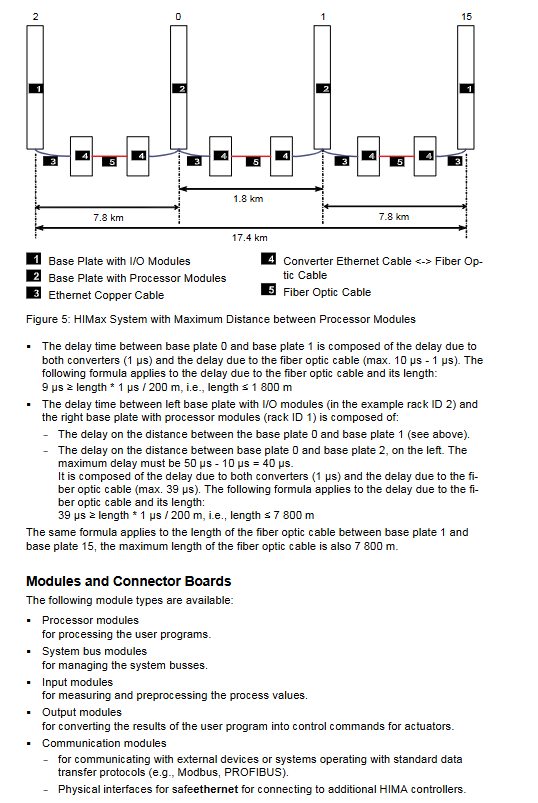
Maximum expansion distance: 19.6km (when processors are centrally arranged), maximum distance between processors is 1.8km;
Substrate interconnection: Through RJ-45 interface, UP/DOWN ports are cascaded, and cross connection of system bus A/B is prohibited.
Redundancy mechanism (high availability core)
HIMax improves availability through full link redundancy design, with the following redundant objects and rules:
Key characteristics of redundant object implementation methods
1-4 redundant configurations of processor modules, supporting seamless takeover when adding/removing faults online, and supporting degraded operation
I/O module module level (2-3 layers) and channel level redundancy can be configured with "backup modules", and faults will not trigger alarms
Dual bus parallel operation of the system bus, independent physical path, single bus failure does not affect system operation
Communication SafeEthernet dual path, standard protocol requires user program management for secure communication delay configurable
Dual 24VDC power supply, module internal decoupling automatically switches in case of single power failure
Programming and Configuration (Based on SILworX Tool)
(1) Core programming functions
Supports up to 32 user programs to run in parallel, with configurable priority and task cycles;
Variable type: global/local/temporary variable, supports CONST (constant) and RETAIN (power down hold) attributes, and the initial value needs to be set to a safe value;
Multi tasking mode:
Mode 1: Shorten CPU cycles based on actual execution time;
Mode 2: High priority programs occupy low priority redundancy time (recommended high availability scenarios);
Mode 3: Fixed cycle operation, waiting for redundancy time to run out;
Event Recording (SOE): Supports Boolean (state change) and scalar (threshold over limit) events, with a buffer capacity of 5000 entries and millisecond timestamps, which can be exported through X-OPC servers.
(2) Loading and Updating
Download: Shutdown to load new configuration, controller needs to be in STOP state;
Reload: Reload modified configurations online without interrupting safe operation, supporting scenarios such as logic modification and variable reallocation;
Operating system update: Supports module level OS upgrade, which needs to be executed in the order of "I/O module → communication module → system bus module → processor module".
(3) Variable forcing (debugging function)
Support global/local variable forcing, with time limits that can be set (automatically canceled upon timeout);
Security restrictions: The forced function can be disabled through the key switch, and only authorized personnel can operate it. Forced operation may prolong the cycle time, and needs to be evaluated in advance.
User management and permission control
(1) Project level management (SILworX project)
Permission types: Security Administrator (Sec Adm, modifiable user management), Read/Write (R/W, full function operation), Read Only (RO, view only);
Configuration restrictions: Up to 100 user groups and 1000 user accounts, account names/passwords are case sensitive.
(2) Controller level management (PES)
Up to 10 user accounts, with permissions divided into 3 categories:
Read only: only view controller status;
Read and write: programming, loading, testing;
Administrator: Modify key configurations such as IP, SRS, operating system, etc;
Default account: Administrator (no password), first use requires modification.
Diagnosis and maintenance
(1) Diagnostic method
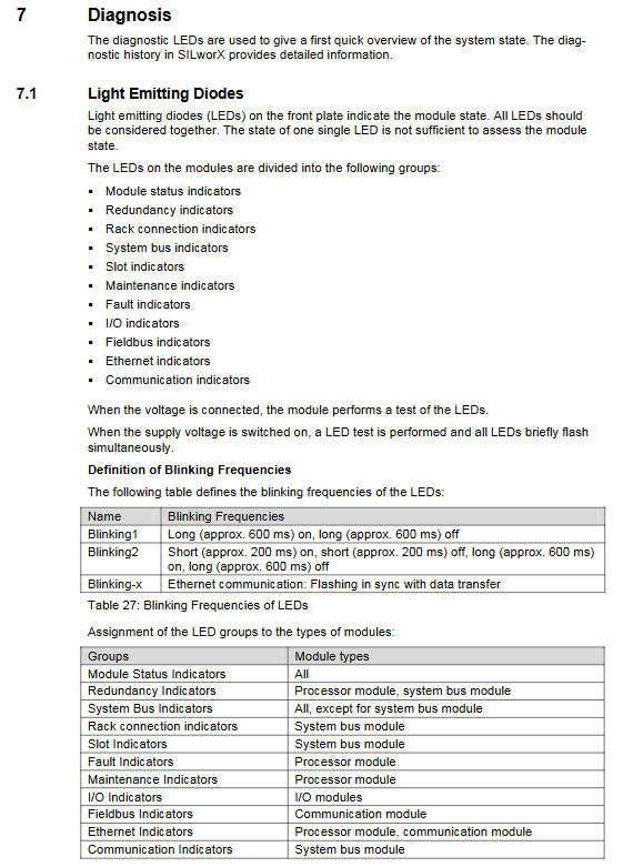
LED indicator lights: 11 types of indicator lights (module status/redundancy/fault/communication, etc.), supporting different flashing frequencies to distinguish states (such as Blinking1: 600ms on/600ms off);
Diagnostic history: Each module stores short-term (fault/event) and long-term (configuration change) logs, with a maximum of 2500 long-term logs for the processor module;
Online diagnosis: SILworX online view displays module status (red=serious fault, yellow=minor fault), supports tooltip to view SRS, connection status and other details.
(2) Maintenance requirements
Regular maintenance: The fan should be replaced every 6 years (at room temperature<40 ℃) or every 3 years (at high temperature>40 ℃); Regular functional testing is required (refer to the Safety Manual);
Fault handling: When a redundant module fails, it will automatically take over. If a non redundant module fails, it needs to be shut down for replacement. The faulty module is only authorized for maintenance by HIMA;
ESD protection: ESD wristbands should be worn during maintenance, and unused modules should be stored in anti-static packaging.
Installation and Startup
(1) Installation specifications
Grounding: L - Single point grounding, grounding resistance ≤ 2 Ω, all components of the cabinet are connected to equipotential through a 16/25mm ² yellow green grounding wire;
Cable: The power line and signal line are arranged separately, and shielded wires are used for analog signals. The shielding layer is grounded at one end;
Heat dissipation: Adequate space should be reserved around the substrate, and blank modules should be installed in unused slots to ensure ventilation.
(2) Start the process
Configure the Rack ID of the substrate (set through the system bus module, safety critical parameters);
Connect SILworX tool, set module IP address and SRS identifier;
Load project configuration (Download/Reload);
Switch the processor module mode switch to Run, and the system will automatically enter the running state;
Verify the diagnostic indicator light: The Run light is always green and the Error light is off, indicating a normal state.
Key specification parameters
Category specific indicators
Hardware scale up to 16 substrates, 4 processor modules, 6400 I/O channels
The maximum storage capacity for each user program is 32KB, and the maximum number of global variables is 523776
SafeEthernet communication has a maximum of 255 connections and a buffer of 1100 bytes
The maximum extension distance of the system bus is 19.6km (fiber optic), and the maximum distance between processors is 1.8km
The minimum cycle time can be configured to 0ms, and the watchdog time is 6-7500ms
- YOKOGAWA
- Reliance
- ADVANCED
- SEW
- ProSoft
- WATLOW
- Kongsberg
- FANUC
- VSD
- DCS
- PLC
- man-machine
- Covid-19
- Energy and Gender
- Energy Access
- Renewable Integration
- Energy Subsidies
- Energy and Water
- Net zero emission
- Energy Security
- Critical Minerals
- A-B
- petroleum
- Mine scale
- Sewage treatment
- cement
- architecture
- Industrial information
- New energy
- Automobile market
- electricity
- Construction site
- HIMA
- ABB
- Rockwell
- Schneider Modicon
- Siemens
- xYCOM
- Yaskawa
- Woodward
- BOSCH Rexroth
- MOOG
- General Electric
- American NI
- Rolls-Royce
- CTI
- Honeywell
- EMERSON
- MAN
- GE
- TRICONEX
- Control Wave
- ALSTOM
- AMAT
- STUDER
- KONGSBERG
- MOTOROLA
- DANAHER MOTION
- Bentley
- Galil
- EATON
- MOLEX
- Triconex
- DEIF
- B&W
- ZYGO
- Aerotech
- DANFOSS
- KOLLMORGEN
- Beijer
- Endress+Hauser
- schneider
- Foxboro
- KB
- REXROTH
- YAMAHA
- Johnson
- Westinghouse
- WAGO
- TOSHIBA
- TEKTRONIX
- BENDER
- BMCM
- SMC
- HITACHI
- HIRSCHMANN
- XP POWER
- Baldor
- Meggitt
- SHINKAWA
- Other Brands
- UniOP
- KUKA
- IBA
- Beckhoff
-
LTI SC52.0040.0012.0000.0 - Servo Drive
-
Lti SC52.0040.0012.0000.0 - Servo Drive
-
Milton Industries LTI Tool By Milton LT1240 - 1/2" Drive Lugnut Remover
-
LTi Drives SO84.200.P030.0000.0-W - Servo Spindle Drive
-
LTI DRIVES LSP08-035-320-30-B0R1PY170 - Servo Motor
-
LTI DRIVES SE84.200.SC00.0001.0-W - Servo Drive
-
Lust CDE34.005.W2.2 - Lti Drives Controller
-
LTi SO84.012.0030.0011.2 - ServoOne Servo Drive
-
LTi Drives SO CM-P.0010.11.00.0 - Servo Drive Controller
-
LTi CDE34.017.W3.0 - Servo Drive
-
LTI Drives CDB32.004, C2.0,SH - Positioning Controller
-
LUST CM-CAN1 - LTi DRIVES Communication Module
-
LTi SO84.012.1030.0000.2 - Servo Drive
-
LTI MOOG CDE54.044 - PITCHMASTER FREQUENCY CONVERTER 181-01019
-
MOOG LTI 181-01019 CDE54.044 - PITCHMASTER FREQUENCY CONVERTER
-
Lust LTi Drives CDE34.010,D2.0 - Servo Drive Controller
-
LTI SO84.032.0003.0101.2 - Servo Drive
-
Seagate 9CC132-302 Harris LTI-CS IRT-34-0021-01 - Hard Drive 160GB
-
LTI SO84.032.0003.0001.2 - Servo Drive
-
LTI SO24.007.0070.0000.1 - SERVO CONTROLLER
-
LTi drive CDA32.003.C3.0.H05-01.PC1 - Servo Drive
-
LTI SO84.016.0030.0000.2 - SERVO CONTROLLER
-
LUST LTI CD A34.008,W1.4, BR - SERVO DRIVE
-
MOOG LTI 181-01019 CDE54.044 - PITCHMASTER FREQUENCY CONVERTER
-
LTI MOOG 181-01019 - PITCH Master Servo Drive CDE54.044
-
LTI SERVO ONE SO84.045.0030.0001.2-W - Drive
-
LUST LTi SO84.032.0040.0000.2 - SERVO ONE DRIVE
-
LTi Drives LSH-074-2-30-3 20/T1,G6.1M - SERVO MOTOR
-
LTI SO84.016.0000.0101.2 - servo drive
-
LTI SA54.0550.0033.0000.0 - Servo Drive
-
LTI SA54.0550.0033.0000.0 - Servo Drive
-
LTI LT 4850 - 3/8" Drive 3-Pc Twist Socket Transmission Drain Plug Removal System
-
LTI Tools LT4400-30 Lock Technology - 3/4" Twist Socket 1/2" Drive Lugnut Remover
-
LTI Tools LT-1400C - 1/2 Drive Wheel Torque Extension Tool
-
LTI Tools LT1250 - 1/2" Drive Dual Sided Socket Lug Nut Remover Tool
-
LTI SO84.032.0003.0101.2 - Servo Drive
-
LTI MOOG 181-01019 - PITCH Master Servo Drive CDE54.044
-
MOOG LTI 181-01019 CDE54.044 - PITCHMASTER FREQUENCY CONVERTER
-
MOOG LTI 181-01019 CDE54.044 - PITCHMASTER FREQUENCY CONVERTER
-
MOOG LTI 181-01019 CDE54.044 - PITCHMASTER FREQUENCY CONVERTER
-
LTI SA54.0550.0033.0000.0 - Servo Drive
-
LTI Tools LT-4800 - 7 Piece Twist Socket 3/8" Drive Oil Drain Plug Removal Set
-
LTI SA54.0550.0033.0000.0 - Servo Drive
-
LTI Drive SO24.007.00300000.0 - Servo Drive
-
LTI TOOLS LTI 1400-I - Drive Wheel Torque Extension
-
LTI Tools LT4400-3 - 3/4" 19mm Twist Socket 1/2" Drive Lugnut
-
LTI TOOLS LTI 1400-BB - Drive Wheel Torque Extension
-
LTI SO84.032.0003.0101.2 - Servo Drive
-
LTI Tools LT-4512 - 3/8" Drive 12mm Twist Socket
-
LTI MOTION Luster SO84.032.0003.0001.2 - Servo Drive
-
LTI Tool By Milton LT1600P - 1" Drive Torx Stick
-
LTI Lust VF1424L,HF,OP2,S56 - Variable Frequency Drive
-
LUST CDA32.004,C1.4,H08,B0 - SERVO DFRIVE CM-CAN1 Module
-
LTI SO84.045.0002.0001.2-W - Drive
-
LTI Lust VF1404M,C9,PT1,BR1 - Inverter Type VF1404M
-
LTI SA54.0550.0033.0000.0 - Servo Drive
-
LTI Tools LT-1400C - 1/2" Drive Wheel Torque Extension
-
Lust LTI DRiVES CDA32.006, C3.0, H09 - Variateur De Fr茅quence Frequency Inverter
-
LTI MOOG CDE54.044 - PITCH master SERVO DRIVE
-
LTI MOOG CDE54.044 - PITCH master SERVO DRIVE
-
LTI SO84.143.0020.0101.2-W - servo drive
-
LTI MOTION SC34.0200.0011.0000.0 - Servo drives
-
LTI SO84.032.0003.0001.2 - Servo Drive
-
LTI DRIVES GmbH MS100 - Assembly Set Mounting Kit
-
LTI SO84.032.0003.0001.2 - Servo Drive
-
LTI SO84.032.0003.0001.2 - Servo Drive
-
LTI MOTION SO84.032.0003.0101.2 - servo drive
-
LTI SO84.032.0003.0101.2 - Servo Drive
-
LTI MOOG CDE54.044 - PITCH master SERVO DRIVE
-
LTI MOTION CDE32.004.C2.4 - Servo drives
-
LTI CDD34.032锛學x.x锛孊R锛孭C1 - Servo Drive
-
Lust LTI DRiVES CDA32.006, C3.0, H09 - Inversor De Frecuencia Frequency Inverter
-
Lust SO84.008.0030.1000.0 - Servo One LTi Drive
-
LTI MOTION SO84.032.0003.0101.2 - Servo drives
-
LUST LTi CDA32.004,C1.4 - SERVO DRIVE
-
LTI MOOG CDE54.044 - PITCH Master SERVO DRIVE
-
LTI KEBA CDB32.004 C2.7, SH - PN: 08673530 Frequency Inverter
-
LTI Tools LT-1400C - 1/2" Drive Wheel Torque Extension
-
LTI LT1400-E - 1/2" Drive Wheel Torque Extension
-
LTI MOOG 181-01019 - PITCH master SERVO DRIVE CDE54.044
-
LTI LSN-097-0510-30-560/T1 - Actuator Motor
-
LTI Tools LT 4800 - 7 Piece 3/8" Drive Twist Socket Oil Drain Plug Removal System
-
LTI DRIVES GmbH MS100 - MONTAGESET Assembly Set Mounting Kit
-
Lti SC52.0040.0012.0000.0 - Servo Drive
-
LTI DRIVES GmbH MS100 - Juego De Montaje Assembly Set Mounting Kit
-
LTi DSM4-14.2-21R83-200 - Drives servomoteur Servo Motor
-
MOOG CDE 54.044.GDA - Pitch Master Industrielle Turbine Lti Drive
-
LTI SO24.004.0030.1000.0 - Servo Drive Controller
-
Lti MOOG CDE54.044 - Pitch Master Servo Drive
-
Lust LTI DRiVES CDA32.006, C3.0, H09 - Inverter
-
LTI MOTION GMBH CDB34.006,W3.0,PC1,H39 - Frequency inverter
-
LTI SO84.032.0003.0001.2 - Servo Drive
-
MOOG CDE 54.044.D - Pitch Master Industrielle Turbine Lti Drive
-
LTI TOOLS LT-1460 - 1/2" DRIVE WHEEL TORQUE EXTENSION KIT 5 PIECE SET
-
Lust Cdb32.003, C2.4 - Lti Drives Servoregulador Frecuencia Servo Controller Inverter
-
Lust LTI DRIVES CDA32.006, C3.0, H09 - Frequency Inverter
-
Lust Lti SO82.004.0030.0000.2 - Servo Drive
-
LTI MOTION SC34.0200.0011.0000.0-SL - Servo drives
-
LTI MOTION SA54.0075.0033.0000.0 - Servo drives
-
LTI MOTION SC32.0075.1011.0000.0 - Servo drives
-
LTI Servo-One Junior SO22.006.0080.1000.0 - Servo Controller Servoregler
-
LUST CDA32.004, C1.4, H08, B0 - Servo Drive & LTI CM-CAN1 Module
-
LTI DRIVES LSP08-035-320-30-B0R1PY170 - Servo Motor
-
LUST LTI CDA32.004,C1.4.H08.B0 - SERVO CONTROLLER DRIVES
-
LUST LTi DRiVES CDS44.072LC1.2 - Servo Drive
-
Lti Servo-One Junior SO22.006.0082.1000.0 - Servo Controller Servoregler
-
LUST CDA32.008,C2.0,HF - Lti DRIVES Spindle Drive Inverter
-
LTI SO22.003.0082.0000.0 - Servo Drives One junior Servo Controller Servoregler
-
Lust Lti Drives CM-CAN1 - Communication Module
-
LUST Lti Drives Vf1202s, G8, I6 - Frequency Inverter Drive
-
LTI DRIVES BR-090.03.540.UR.H38 - Bremswiderstand Brake Resistor
-
LTi DRIVES PM-E40.2DRA054P - Wind Turbine Pitch Control Inverter
-
LTi Drives GmbH br-110.01.540-UR - Brake Resistor
-
LTI Drives LSN-097-0960-30-0560/T1,S4,B - Servo Motor
-
LUST CDA34.006.C2.0 - LTI Drives Servoregler
-
LUST LTI DRIVES SERVO ONE JUNIOR SO24.002.0020.0000.1 - Servo Drive Controller
-
LTI MOTION SO84.032.0003.0001.2 - Servo drives
-
LTI DDTD750V2-120 - IBOP ACTUATOR CYLINDER FOR TOP DRIVE
-
LTI CDE32.004, C2.4 - SERVO DRIVE
-
LUST LTI DRIVES CDD34.017 W3.4PC1 - Servo Drive Controller
-
LTI CDA3208,C3,0,HF - AC SERVO DRIVE
-
LUST LTI DRIVES LSH-074-3-30-560/T1,G6.1S - SERVO MOTOR
-
LUST Lti CDB32.004.C2.4.SH - AC Servo Drive
-
LTi CDA32.006, C3.0, H09 - Servo Drive
-
LTI SO22.003.0010.0000.0 - Servo Drive Servo one junior Servoregler Controller
-
LTi Drives DSM4-14.2-21R83-200 - Servo Motor
-
LUST Lti Drives Lsh-097-1-30-560/T1, 1R - Servomotor
-
LTI 1237 - 7 Piece 1/2" Drive Flip Socket Set

K-JIANG

Add: Jimei North Road, Jimei District, Xiamen, Fujian, China
Tell:+86-15305925923