
K-WANG


HIMax X-FAN system fan
HIMax X-FAN system fan
Core Features and Classification of Products
(1) Product positioning and functionality
X-FAN is a necessary component of the HIMax system, installed directly above the substrate to provide heat dissipation for modules with ventilation openings on top and bottom. Hot air is discharged upwards, and sufficient heat dissipation space needs to be reserved;
Core functions: heat dissipation and ventilation, fan operation monitoring (voltage/speed/line status), fault alarm (LED indicator light+fault relay).
(2) Model classification and adaptation relationship
Divided into 8 models based on installation method and air volume noise, suitable for different substrates, as follows:
Model, installation method, fan quantity, suitable substrate, air volume characteristics, noise characteristics, recommended usage scenarios
X-FAN 10 01 Backboard 2 X-BASE PLATE 10 01 High (240~440m ³/h) High (≈ 63dB (A)) High temperature environment, unmanned scene
X-FAN 15 01 Backboard 3 X-BASE PLATE 15 01 High (360~660m ³/h) High (≈ 65dB (A)) High temperature environment, unmanned scene
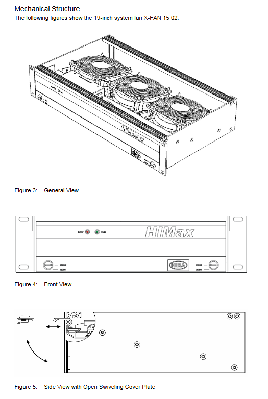
X-FAN 15 02 19 inch rack 3 X-BASE PLATE 15 02 high (360~660m ³/h) high (≈ 65dB (A)) high temperature environment, unmanned scene
X-FAN 18 01 Backboard 4 X-BASE PLATE 18 01 High (480~880m ³/h) High (≈ 67dB (A)) High temperature environment, unmanned scene
X-FAN 10 03 Backboard 2 X-BASE PLATE 10 01 Conventional (160~250m ³/h) Low (≈ 45dB (A)) Temperature<40 ℃, Noise Sensitive Scene (such as manned duty room)
X-FAN 15 03 Backboard 3 X-BASE PLATE 15 01 Conventional (240~375m ³/h) Low (≈ 47dB (A)) Temperature<40 ℃, Noise Sensitive Scene
X-FAN 15 04 19 inch rack 3 X-BASE PLATE 15 02 conventional (240~375m ³/h) low (≈ 47dB (A)) temperature<40 ℃, noise sensitive scene
X-FAN 18 03 Backboard 4 X-BASE PLATE 18 01 Conventional (320~500m ³/h) Low (≈ 49dB (A)) Temperature<40 ℃, Noise Sensitive Scene
(3) Key components and functions
Identification label: including product name, conformity mark, barcode, part number, software and hardware versions, operating voltage, explosion-proof specifications (if applicable), and production year;
Mechanical structure: Made of aluminum alloy, with left and right mounting flanges and a rotatable cover plate (to be opened when installing/disassembling modules);
Power supply design: Supports L1+/L2+redundant power supply. When using a single power supply, jumper wires need to be connected between terminals 3 (L2+) and 5 (L1+) to avoid monitoring false alarms;
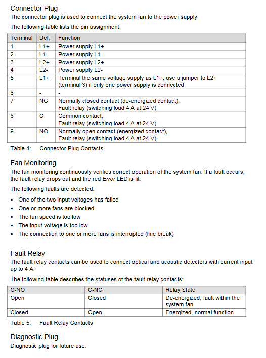
Fan monitoring: Real time detection of voltage abnormalities, fan stalling, low speed, line interruptions, and other faults. When a fault occurs, the red Error LED lights up and the fault relay is released;
Indicator lights: 2 LEDs on the front, green Run LED (lit when power supply is normal), red Error LED (lit when faulty).
Core technical parameters
Specific indicators for parameter categories
Power supply parameters Operating voltage: 24VDC (fluctuation range -15%~+20%), supporting redundant power supply
Current specification X-FAN 10 01:3A; X-FAN 15 01/15 02:3A; X-FAN 18 01:4A; X-FAN 10 03:0.4A
Fault relay switching current: 4A/30VDC, including normally closed (NC), common (C), and normally open (NO) contacts
Environmental parameters: Operating temperature 0~+60 ℃, storage temperature -40~+85 ℃, relative humidity ≤ 95% (no condensation)
Physical parameter dimensions (H × W × D): 88.1 × 358 × 259.5mm~88.1 × 594 × 259.5mm; Weight: 2.7~4.5kg
Protection level IP20
Installation and startup process
(1) Installation preparation
Tools: 0.4 × 2.5mm flathead screwdriver, wire stripping pliers;
Installation kit: M6 bolts and washers are required for backplate installation (not included in the supply scope), and HIMA special kit (M 2212, part number 99 0000115) is required for 19 inch rack installation;
Wire requirements: The maximum cross-sectional area of single strand/multi strand/thin stranded wire is 1.5mm ², and the thin stranded wire needs to be equipped with a wire end sleeve, with a stripping length of 6mm and a tightening torque of 0.2~0.25Nm.
(2) Installation steps
Key steps of installation method
Backboard installation (such as X-FAN 10 01): 1. Use M6 bolts to fix the fan on the backboard above the substrate; 2. Confirm the spacing between threaded holes according to the dimension diagram; 3. When the bolt is tightened halfway, clamp the fan into the base plate locking bolt; 4. Tighten the bolts and establish a conductive connection between the backplate and the ground; 5. Verify the firmness of installation
19 inch rack installation (such as X-FAN 15 02): 1. Secure the fan with cage nuts, M6 × 16 cross screws, and washers from a specialized kit; 2. Insert the fan into the locking bolt of the substrate; 3. Tighten the fasteners at the four elongated holes; 4. Establish a conductive connection between the fan and the ground; 5. Verify the firmness of installation
(3) Power supply connection
Peel off the insulation layer of the wire (length 6mm);
Connect the power supply according to the terminal definition: terminals 1 (L1+), 2 (L1-), 3 (L2+), 4 (L2-);
When using a single power supply, a jumper should be connected between terminals 3 and 5;
Tighten the terminals with a screwdriver to ensure a reliable connection.
(4) Installation spacing requirements
High wind volume model (X-FAN 10 01/15 01/18 01): 1RU (44.45mm) spacing needs to be reserved above and below;
Low air volume model (X-FAN 10 03/15 03/18 03): A spacing of 2RU (88.9mm) needs to be reserved above and below;
19 inch rack model (X-FAN 15 02/15 04): The rear should have an opening and the space should be unobstructed.
Operation and maintenance
(1) Operation monitoring
No additional operation is required, the status is determined by the front LED: green constant light=normal operation, red constant light=fault;
Fault alarm can be achieved by connecting the fault relay contact to the sound and light alarm (maximum current 4A).
(2) Maintenance requirements
Replacement cycle: Replace every 6 years at normal operating temperature (<40 ℃); Replace every 3 years in high temperature environments (>40 ℃), and it is recommended to return to the factory for maintenance;
Replacement specification: The same model or an alternative model approved by HIMA must be used. When replacing, the requirements of the System Manual and Safety Manual must be followed;
Maintenance permission: Only HIMA manufacturers have the right to repair, and users are not allowed to disassemble and repair on their own;
ESD protection: Maintenance personnel must have ESD protection knowledge to avoid electrostatic damage to electronic components.
Transportation and disposal
Transportation: Original packaging is required to prevent mechanical damage and electrostatic discharge. Original packaging is only used for storage and additional protection is required during transportation;
Disposal: Industrial customers are responsible for the environmental disposal of scrapped hardware and can apply to HIMA to sign a disposal agreement. All materials must be disposed of in accordance with ecological and environmental requirements;
Deactivation: Disconnect the power to complete the deactivation.
- YOKOGAWA
- Reliance
- ADVANCED
- SEW
- ProSoft
- WATLOW
- Kongsberg
- FANUC
- VSD
- DCS
- PLC
- man-machine
- Covid-19
- Energy and Gender
- Energy Access
- Renewable Integration
- Energy Subsidies
- Energy and Water
- Net zero emission
- Energy Security
- Critical Minerals
- A-B
- petroleum
- Mine scale
- Sewage treatment
- cement
- architecture
- Industrial information
- New energy
- Automobile market
- electricity
- Construction site
- HIMA
- ABB
- Rockwell
- Schneider Modicon
- Siemens
- xYCOM
- Yaskawa
- Woodward
- BOSCH Rexroth
- MOOG
- General Electric
- American NI
- Rolls-Royce
- CTI
- Honeywell
- EMERSON
- MAN
- GE
- TRICONEX
- Control Wave
- ALSTOM
- AMAT
- STUDER
- KONGSBERG
- MOTOROLA
- DANAHER MOTION
- Bentley
- Galil
- EATON
- MOLEX
- Triconex
- DEIF
- B&W
- ZYGO
- Aerotech
- DANFOSS
- KOLLMORGEN
- Beijer
- Endress+Hauser
- schneider
- Foxboro
- KB
- REXROTH
- YAMAHA
- Johnson
- Westinghouse
- WAGO
- TOSHIBA
- TEKTRONIX
- BENDER
- BMCM
- SMC
- HITACHI
- HIRSCHMANN
- XP POWER
- Baldor
- Meggitt
- SHINKAWA
- Other Brands
- UniOP
- KUKA
- IBA
- Beckhoff
-
LTI SC52.0040.0012.0000.0 - Servo Drive
-
Lti SC52.0040.0012.0000.0 - Servo Drive
-
Milton Industries LTI Tool By Milton LT1240 - 1/2" Drive Lugnut Remover
-
LTi Drives SO84.200.P030.0000.0-W - Servo Spindle Drive
-
LTI DRIVES LSP08-035-320-30-B0R1PY170 - Servo Motor
-
LTI DRIVES SE84.200.SC00.0001.0-W - Servo Drive
-
Lust CDE34.005.W2.2 - Lti Drives Controller
-
LTi SO84.012.0030.0011.2 - ServoOne Servo Drive
-
LTi Drives SO CM-P.0010.11.00.0 - Servo Drive Controller
-
LTi CDE34.017.W3.0 - Servo Drive
-
LTI Drives CDB32.004, C2.0,SH - Positioning Controller
-
LUST CM-CAN1 - LTi DRIVES Communication Module
-
LTi SO84.012.1030.0000.2 - Servo Drive
-
LTI MOOG CDE54.044 - PITCHMASTER FREQUENCY CONVERTER 181-01019
-
MOOG LTI 181-01019 CDE54.044 - PITCHMASTER FREQUENCY CONVERTER
-
Lust LTi Drives CDE34.010,D2.0 - Servo Drive Controller
-
LTI SO84.032.0003.0101.2 - Servo Drive
-
Seagate 9CC132-302 Harris LTI-CS IRT-34-0021-01 - Hard Drive 160GB
-
LTI SO84.032.0003.0001.2 - Servo Drive
-
LTI SO24.007.0070.0000.1 - SERVO CONTROLLER
-
LTi drive CDA32.003.C3.0.H05-01.PC1 - Servo Drive
-
LTI SO84.016.0030.0000.2 - SERVO CONTROLLER
-
LUST LTI CD A34.008,W1.4, BR - SERVO DRIVE
-
MOOG LTI 181-01019 CDE54.044 - PITCHMASTER FREQUENCY CONVERTER
-
LTI MOOG 181-01019 - PITCH Master Servo Drive CDE54.044
-
LTI SERVO ONE SO84.045.0030.0001.2-W - Drive
-
LUST LTi SO84.032.0040.0000.2 - SERVO ONE DRIVE
-
LTi Drives LSH-074-2-30-3 20/T1,G6.1M - SERVO MOTOR
-
LTI SO84.016.0000.0101.2 - servo drive
-
LTI SA54.0550.0033.0000.0 - Servo Drive
-
LTI SA54.0550.0033.0000.0 - Servo Drive
-
LTI LT 4850 - 3/8" Drive 3-Pc Twist Socket Transmission Drain Plug Removal System
-
LTI Tools LT4400-30 Lock Technology - 3/4" Twist Socket 1/2" Drive Lugnut Remover
-
LTI Tools LT-1400C - 1/2 Drive Wheel Torque Extension Tool
-
LTI Tools LT1250 - 1/2" Drive Dual Sided Socket Lug Nut Remover Tool
-
LTI SO84.032.0003.0101.2 - Servo Drive
-
LTI MOOG 181-01019 - PITCH Master Servo Drive CDE54.044
-
MOOG LTI 181-01019 CDE54.044 - PITCHMASTER FREQUENCY CONVERTER
-
MOOG LTI 181-01019 CDE54.044 - PITCHMASTER FREQUENCY CONVERTER
-
MOOG LTI 181-01019 CDE54.044 - PITCHMASTER FREQUENCY CONVERTER
-
LTI SA54.0550.0033.0000.0 - Servo Drive
-
LTI Tools LT-4800 - 7 Piece Twist Socket 3/8" Drive Oil Drain Plug Removal Set
-
LTI SA54.0550.0033.0000.0 - Servo Drive
-
LTI Drive SO24.007.00300000.0 - Servo Drive
-
LTI TOOLS LTI 1400-I - Drive Wheel Torque Extension
-
LTI Tools LT4400-3 - 3/4" 19mm Twist Socket 1/2" Drive Lugnut
-
LTI TOOLS LTI 1400-BB - Drive Wheel Torque Extension
-
LTI SO84.032.0003.0101.2 - Servo Drive
-
LTI Tools LT-4512 - 3/8" Drive 12mm Twist Socket
-
LTI MOTION Luster SO84.032.0003.0001.2 - Servo Drive
-
LTI Tool By Milton LT1600P - 1" Drive Torx Stick
-
LTI Lust VF1424L,HF,OP2,S56 - Variable Frequency Drive
-
LUST CDA32.004,C1.4,H08,B0 - SERVO DFRIVE CM-CAN1 Module
-
LTI SO84.045.0002.0001.2-W - Drive
-
LTI Lust VF1404M,C9,PT1,BR1 - Inverter Type VF1404M
-
LTI SA54.0550.0033.0000.0 - Servo Drive
-
LTI Tools LT-1400C - 1/2" Drive Wheel Torque Extension
-
Lust LTI DRiVES CDA32.006, C3.0, H09 - Variateur De Fr茅quence Frequency Inverter
-
LTI MOOG CDE54.044 - PITCH master SERVO DRIVE
-
LTI MOOG CDE54.044 - PITCH master SERVO DRIVE
-
LTI SO84.143.0020.0101.2-W - servo drive
-
LTI MOTION SC34.0200.0011.0000.0 - Servo drives
-
LTI SO84.032.0003.0001.2 - Servo Drive
-
LTI DRIVES GmbH MS100 - Assembly Set Mounting Kit
-
LTI SO84.032.0003.0001.2 - Servo Drive
-
LTI SO84.032.0003.0001.2 - Servo Drive
-
LTI MOTION SO84.032.0003.0101.2 - servo drive
-
LTI SO84.032.0003.0101.2 - Servo Drive
-
LTI MOOG CDE54.044 - PITCH master SERVO DRIVE
-
LTI MOTION CDE32.004.C2.4 - Servo drives
-
LTI CDD34.032锛學x.x锛孊R锛孭C1 - Servo Drive
-
Lust LTI DRiVES CDA32.006, C3.0, H09 - Inversor De Frecuencia Frequency Inverter
-
Lust SO84.008.0030.1000.0 - Servo One LTi Drive
-
LTI MOTION SO84.032.0003.0101.2 - Servo drives
-
LUST LTi CDA32.004,C1.4 - SERVO DRIVE
-
LTI MOOG CDE54.044 - PITCH Master SERVO DRIVE
-
LTI KEBA CDB32.004 C2.7, SH - PN: 08673530 Frequency Inverter
-
LTI Tools LT-1400C - 1/2" Drive Wheel Torque Extension
-
LTI LT1400-E - 1/2" Drive Wheel Torque Extension
-
LTI MOOG 181-01019 - PITCH master SERVO DRIVE CDE54.044
-
LTI LSN-097-0510-30-560/T1 - Actuator Motor
-
LTI Tools LT 4800 - 7 Piece 3/8" Drive Twist Socket Oil Drain Plug Removal System
-
LTI DRIVES GmbH MS100 - MONTAGESET Assembly Set Mounting Kit
-
Lti SC52.0040.0012.0000.0 - Servo Drive
-
LTI DRIVES GmbH MS100 - Juego De Montaje Assembly Set Mounting Kit
-
LTi DSM4-14.2-21R83-200 - Drives servomoteur Servo Motor
-
MOOG CDE 54.044.GDA - Pitch Master Industrielle Turbine Lti Drive
-
LTI SO24.004.0030.1000.0 - Servo Drive Controller
-
Lti MOOG CDE54.044 - Pitch Master Servo Drive
-
Lust LTI DRiVES CDA32.006, C3.0, H09 - Inverter
-
LTI MOTION GMBH CDB34.006,W3.0,PC1,H39 - Frequency inverter
-
LTI SO84.032.0003.0001.2 - Servo Drive
-
MOOG CDE 54.044.D - Pitch Master Industrielle Turbine Lti Drive
-
LTI TOOLS LT-1460 - 1/2" DRIVE WHEEL TORQUE EXTENSION KIT 5 PIECE SET
-
Lust Cdb32.003, C2.4 - Lti Drives Servoregulador Frecuencia Servo Controller Inverter
-
Lust LTI DRIVES CDA32.006, C3.0, H09 - Frequency Inverter
-
Lust Lti SO82.004.0030.0000.2 - Servo Drive
-
LTI MOTION SC34.0200.0011.0000.0-SL - Servo drives
-
LTI MOTION SA54.0075.0033.0000.0 - Servo drives
-
LTI MOTION SC32.0075.1011.0000.0 - Servo drives
-
LTI Servo-One Junior SO22.006.0080.1000.0 - Servo Controller Servoregler
-
LUST CDA32.004, C1.4, H08, B0 - Servo Drive & LTI CM-CAN1 Module
-
LTI DRIVES LSP08-035-320-30-B0R1PY170 - Servo Motor
-
LUST LTI CDA32.004,C1.4.H08.B0 - SERVO CONTROLLER DRIVES
-
LUST LTi DRiVES CDS44.072LC1.2 - Servo Drive
-
Lti Servo-One Junior SO22.006.0082.1000.0 - Servo Controller Servoregler
-
LUST CDA32.008,C2.0,HF - Lti DRIVES Spindle Drive Inverter
-
LTI SO22.003.0082.0000.0 - Servo Drives One junior Servo Controller Servoregler
-
Lust Lti Drives CM-CAN1 - Communication Module
-
LUST Lti Drives Vf1202s, G8, I6 - Frequency Inverter Drive
-
LTI DRIVES BR-090.03.540.UR.H38 - Bremswiderstand Brake Resistor
-
LTi DRIVES PM-E40.2DRA054P - Wind Turbine Pitch Control Inverter
-
LTi Drives GmbH br-110.01.540-UR - Brake Resistor
-
LTI Drives LSN-097-0960-30-0560/T1,S4,B - Servo Motor
-
LUST CDA34.006.C2.0 - LTI Drives Servoregler
-
LUST LTI DRIVES SERVO ONE JUNIOR SO24.002.0020.0000.1 - Servo Drive Controller
-
LTI MOTION SO84.032.0003.0001.2 - Servo drives
-
LTI DDTD750V2-120 - IBOP ACTUATOR CYLINDER FOR TOP DRIVE
-
LTI CDE32.004, C2.4 - SERVO DRIVE
-
LUST LTI DRIVES CDD34.017 W3.4PC1 - Servo Drive Controller
-
LTI CDA3208,C3,0,HF - AC SERVO DRIVE
-
LUST LTI DRIVES LSH-074-3-30-560/T1,G6.1S - SERVO MOTOR
-
LUST Lti CDB32.004.C2.4.SH - AC Servo Drive
-
LTi CDA32.006, C3.0, H09 - Servo Drive
-
LTI SO22.003.0010.0000.0 - Servo Drive Servo one junior Servoregler Controller
-
LTi Drives DSM4-14.2-21R83-200 - Servo Motor
-
LUST Lti Drives Lsh-097-1-30-560/T1, 1R - Servomotor
-
LTI 1237 - 7 Piece 1/2" Drive Flip Socket Set

K-JIANG

Add: Jimei North Road, Jimei District, Xiamen, Fujian, China
Tell:+86-15305925923