
K-WANG


HONEYWELL INTELLIKNIGHT®MODEL 5700 Addressable Fire Alarm Control Panel
HONEYWELL INTELLIKNIGHT ® MODEL 5700 Addressable Fire Alarm Control Panel
Honeywell Silent Knight INTELLIKNIGHT ® Model 5700 is an address based fire alarm control panel (FACP) that complies with UL 864 standards. It supports SK/SD series SLC address based devices (up to 50 detectors+50 modules), has dual telephone line digital alarm communicators (DACT), 2 sets of 2.5A Notification/Aux power circuits, 125 software partitions/125 output groups, integrates 2 programmable relays+1 fault relay, supports JumpStart automatic programming, 1000 event records, multi module expansion (5860 remote annunitor, etc.), adapts to Class A/B wiring, operates in a temperature range of 0 ° C-49 ° C, and requires installation and maintenance in accordance with NFPA 72 specifications. It is widely used in commercial/industrial fire scenarios. Detection, alarm and emergency communication.
Product core positioning and core features
core positioning
The core equipment of the UL 864 standard address based fire alarm system integrates fire detection, alarm notification, emergency communication, and event recording functions, supports SK/SD two series of address based devices, and is suitable for fire safety protection in multiple scenarios such as commercial and industrial.
Core strengths
Flexible Expansion: Supports 8 expansion modules (5860 remote annunitor, 5824 printer interface, etc.), expandable NAC circuits, relay outputs, etc;
Convenient programming: JumpStart automatic programming function, automatically recognizes SLC devices and configures default parameters, reducing manual operation;
High reliability: dual telephone line redundancy, backup battery life (24/60 hours standby), 1000 event records (not lost in case of power failure);
Safety compliance: Supports Class A/B cabling, fault isolation, and anti false alarm mechanism (alarm verification/2-count mode), in compliance with NFPA 72 specifications.
Key technical specifications
Specification category specific parameters
Power supply parameters AC input: 120VAC (60Hz, 1.5A); Backup battery: 12V in series with 24V (7-35AH, main cabinet can accommodate 7AH, large battery requires RBB accessory cabinet)
Equipment capacity SLC devices: up to 50 SK detectors+50 SK modules, or 50 SD series devices (non mixable)
Output capability NAC/Aux circuit: 2 groups, each group 2.5A (total load ≤ 2.5A); Relays: 3 Form C( 2.5A@27.4VDC )
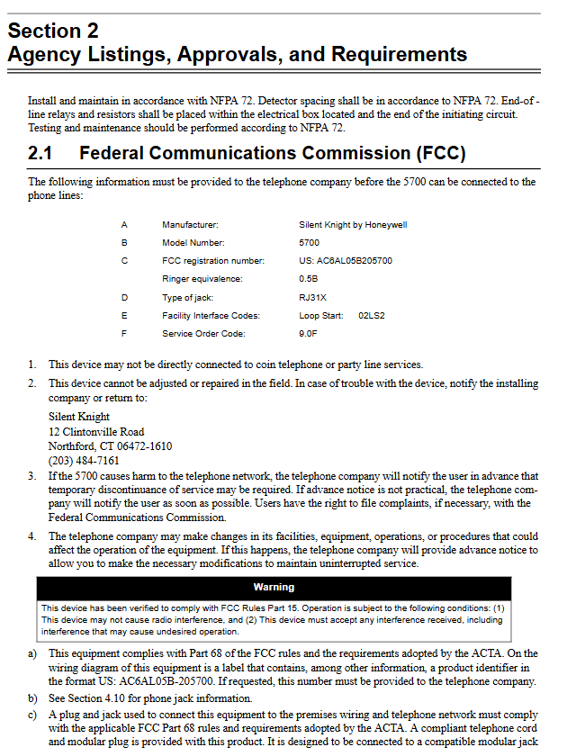
Communication interface telephone line: 2 channels (RJ31X, FCC certified); SLC circuit: Class A/B (22AWG maximum 1200 feet); SBUS: 4-core shielded wire (up to 6000 feet)
Environmental conditions: working temperature: 0-49 ° C; humidity: 10-93% RH (non condensing); Protection: Indoor dry environment (avoid condensation/water immersion)
Software configuration partition: 125; Output group: 125; Event records: 1000 records; User permissions: 20 user profiles
Hardware composition and module adaptation
Core hardware components
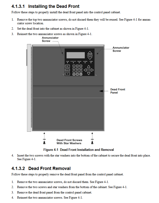
Main control panel: including LCD display screen, operation buttons, terminal block (SLC/SBUS/NAC/power);
Backup battery: 7-35AH 12V battery (series 24V), supports remote battery cabinet (RBB);
Basic interfaces: SLC circuit terminal (SLC IN/OUT/PROG), SBUS expansion terminal, telephone line terminal (TELCO 1/2).
Compatible devices and modules
|Equipment type | Representative model | Core function|
|SLC detector | SK Photo (photoelectric), SD505-HEAT (temperature sensing) | Fire detection (smoke/temperature/CO)|
|SLC module | SK Monitor, SD500-ARM (relay) | Contact monitoring, relay output|
|Expansion Module | 5860 Remote Annunciator | Remote Status Display and Operation|
|Expansion module | 5824 Serial/Parallel interface | Event printing, log output|
|Power module | 5496 intelligent power extender | Added 4 NAC/Aux circuits|
|Auxiliary equipment | B200S sound and light base, manual alarm button | sound and light alarm, manual trigger|
Installation specifications
Installation requirements
Location: Indoor dry place, away from condensation/corrosive environment, easy to operate and maintain;
Fixed: Wall mounted installation (12 three-quarters "W × 15-1/8" H × 3-3/8 "D), 3/4" plywood needs to be added to the concrete wall;
Wiring: Separation of high/low voltage lines, single point grounding of shielded wires, SLC circuit Class A/B wiring (EOL resistance 4.7K Ω);
Power supply: AC wiring requires professional electrician operation, batteries should be connected in series (avoid parallel connection), and the polarity should be correct.
Wiring distance limit (copper wire)
|Line type | 22AWG | 18AWG | 16AWG | 14AWG|
|SK SLC circuit | 1200 feet | 3100 feet | 4900 feet | 7900 feet|
|SD SLC circuit | 1500 feet | 3900 feet | 6200 feet | 10000 feet|
|SBUS Expansion | 185 feet (1A load) | 469 feet (1A load) | 746 feet (1A load) | 1181 feet (1A load)|
Core programming process
Basic Programming (JumpStart Automatic Programming)
Trigger condition: Execute after SLC device wiring and addressing;
Automatic configuration: Identify device types, create Zone 1 (grouping all devices together), and enable 3 output groups;
Subsequent adjustments: Partition, output mapping, and alarm mode can be manually modified.
Key programming items
Partition configuration: 125 partitions, with adjustable names and alarm delay (1/2 count, PAS, etc.);
Output group mapping: 11 types of events (detector alarms, water flow alarms, etc.) can be mapped to 8 output groups;
Alarm modes: 1-Count (instant alarm), 2-Count (dual detector confirmation), Alarm Ver. (alarm verification);
Communication settings: 4 report accounts, phone dialing parameters (prefix/ringtone), DACT protocol (CID/SIA).
Permission Management
Supports 20 user profiles, customizable access codes (4-7 bits), and operation permissions (programming/resetting/testing);
Default code: User code 1111, installation code 123456.
System operation and maintenance
Basic Operations
Daily functions: time setting, event inquiry, fire drill (manual/automatic 10 minute timeout);
Alarm processing: mute (SILENSE key), reset (RESET key), event confirmation;
Testing functions: walking test (with/without report), dialing test, indicator test (LED/PZT).
Maintenance requirements
Regular testing: monthly walking test, annual detector sensitivity calibration, and full system inspection every 6 months;
Battery maintenance: Regularly check the capacity and replace it according to specifications (to avoid overcharging/overdischarging);
Event management: Regularly export event logs and clear expired records (up to 1000).
Common fault handling
|Fault phenomenon | Possible cause | Handling method|
|No power indication | AC power failure, poor battery contact | Check AC input, battery wiring|
|False alarm | Detector contamination, sensitivity drift | Clean detector, calibrate sensitivity|
|Communication failure | Telephone line interruption, incorrect dialing parameters | Check the line, reconfigure dialing parameters|
|SLC circuit fault | Line short circuit, EOL resistor missing | Troubleshooting wiring, installing 4.7K Ω resistor|
Compliance and Responsibility Statement
The system is only a fire warning tool and does not guarantee complete avoidance of property damage or personal injury;
Installation and maintenance must be carried out by authorized professionals, strictly following NFPA 72 and local fire safety regulations;
The warranty does not cover malfunctions caused by water damage, misoperation, or failure to maintain according to specifications.
- YOKOGAWA
- Reliance
- ADVANCED
- SEW
- ProSoft
- WATLOW
- Kongsberg
- FANUC
- VSD
- DCS
- PLC
- man-machine
- Covid-19
- Energy and Gender
- Energy Access
- Renewable Integration
- Energy Subsidies
- Energy and Water
- Net zero emission
- Energy Security
- Critical Minerals
- A-B
- petroleum
- Mine scale
- Sewage treatment
- cement
- architecture
- Industrial information
- New energy
- Automobile market
- electricity
- Construction site
- HIMA
- ABB
- Rockwell
- Schneider Modicon
- Siemens
- xYCOM
- Yaskawa
- Woodward
- BOSCH Rexroth
- MOOG
- General Electric
- American NI
- Rolls-Royce
- CTI
- Honeywell
- EMERSON
- MAN
- GE
- TRICONEX
- Control Wave
- ALSTOM
- AMAT
- STUDER
- KONGSBERG
- MOTOROLA
- DANAHER MOTION
- Bentley
- Galil
- EATON
- MOLEX
- Triconex
- DEIF
- B&W
- ZYGO
- Aerotech
- DANFOSS
- KOLLMORGEN
- Beijer
- Endress+Hauser
- schneider
- Foxboro
- KB
- REXROTH
- YAMAHA
- Johnson
- Westinghouse
- WAGO
- TOSHIBA
- TEKTRONIX
- BENDER
- BMCM
- SMC
- HITACHI
- HIRSCHMANN
- XP POWER
- Baldor
- Meggitt
- SHINKAWA
- Other Brands
- UniOP
- KUKA
- IBA
- Beckhoff
-
ADLINK CPCI-6860A - 51-31310-OB10 industrial motherboard CompactPCI SBC
-
ADLINK AmITX-SL-G-H110 - 51-7A104-0A30 Mini-ITX Industrial Motherboard
-
ADLINK PXI-2005-003 - CPCI Industrial PC Data Acquisition Card Multi-Function DAQ
-
ADLINK DININ-814M - 51-14032-0A3D SCSI-100P cable connection Interface Terminal Board
-
ADLINK CPCI-3920NA/C2D15/M1G - 3U CompactPCI Intel Core 2 Duo Single Board Computer
-
ADLINK PCIE-8560 - 51-18014-0A20 Communication Card High Speed DAQ
-
ADLINK PCI-C154+ - Motion Control Card 4-axis Motion Controller Board
-
ADLINK PCI-RTV24 - image capture card Analog Video Frame Grabber
-
ADLINK NuPRO-842LV/P - 51-41360-0B30 Industrial Motherboard CPU Board
-
ADLINK cBP-3208/3208R - CPCI Board 3U 8-Slot CompactPCI Backplane
-
ADLINK PCI-8164 - 4-Axis Motion Controller PCI Card 51-12406-0A40
-
ADLINK PCIe-GIE64+ - 4-CH GigE Vision PoE+ Frame Grabber Video Capture Card
-
ADLINK CPCI-6860 / 6860A - CompactPCI Dual Xeon Single Board Computer
-
ADLINK IEC-915GV - REV 1.1 Industrial motherboard CPU Board
-
ADLINK ND-6520 - Technology RS-232 to RS-422RS-485 Converter NuDAM Module
-
ADLINK RTV-24 / PCI-MP4S - 51-12519-1C30 4-Channel Real Time Video Capture Board
-
ADLINK cPCI-6910 / cPCI-6910AM/M1G - cPCI-6910AM/DXL16/M1G/S80G(G)-3120 BOARD CompactPCI SBC
-
ADLINK NUPRO-A40H - Linghua 51-41807-1A30 Industrial Control Computer Motherboard
-
ADLINK USB-3488A - USB to GPIB INTERFACE USB-3488A(G) Controller Module
-
ADLINK PCI-8134A - motion control card 4-Axis Controller Card
-
ADLINK PCI-7432 - Board 32-Channel input / 32-output Isolated Digital I/O PCI Card
-
ADLINK PCI-8134A - 51-12421-0A10 motion controller card tested
-
ADLINK LPCIe-7230 - 32 CH Isolated Input/output Card 2 Interrupts Low Profile PCIe
-
ADLINK NuPRO-E340 - industrial computer motherboard 51-47807-0A30 PICMG 1.3 SHB
-
ADLINK PCI-7434 - High-speed Digital Acquisition Card 64-CH Isolated DO Card
-
ADLINK NuPRO-E330 - 51-41805-0A20 Indsutrial Board SHB Single Board Computer
-
ADLINK PCI-7248 - OPTO-22 48 CHANNEL DIO DIGITAL TTL/DTL I/O 51-12006-0A40 GP
-
ADLINK PCI-8134 - Motion control card 4-Axis Controller Card
-
ADLINK AMP-208C - Movimiento Control Tarjeta 51-12420-1A20 W/Expansión & Breakout
-
ADLINK PCI-8164 - 51-12406-0A40 PCB Board 4-Axis Motion Controller Card
-
ADLINK DIN-68Y-SGII / DIN-68M-J3A - Terminal Board Connector Interface Block
-
ADLINK PCIe-7432 - Technology 51-18402-0A10 PCIe Card With High Input Range
-
ADLINK PCI-8144 / PCI-8144N - Motion control card 4-Axis Stepper Controller Card
-
ADLINK HSL-HUB3/REPEATER - HIGH SPEED LINK EXTENSION MODULES Distributed Hub Module
-
ADLINK ND-6017 - Data Logging + Acquisition 8CH A/D input Mod NuDAM Module
-
ADLINK LPCIe-7250 - data acquisition card Low Profile 8-CH Relay Output Card
-
ADLINK PCI-7432 - I/O card 64-CH Isolated Digital Input Output PCI Card
-
ADLINK IMB-M43H - industrial control computer motherboard Q87 Chip Micro-ATX
-
ADLINK MP-C154 - Motion control Card 4-Axis Motion Controller Board
-
ADLINK PCI-RTV24 - image capture card Video Frame Grabber Card
-
ADLINK PCI-7250 - 8-CH Relay Output & 8-CH Isolated DI Card
-
ADLINK PCI-6308V - 8-CH 12-Bit Isolated Analog Output PCI Card PCB-I-E-1148=6EX2
-
ADLINK PCI-7248 - capture card 48-CH Opto-22 Compatible DIO Card
-
ADLINK HSL-AI16A02-M-VV - Analog Input Output Distributed Module
-
ADLINK NuPRO-A301 - Rev:1.4 NUPRO-A301 PICMG Full-Size Single Board Computer
-
ADLINK PCI-6208V-GL - 8-CH Voltage Analog Output PCI Card
-
ADLINK PCI-8134A - 51-12421-0A10 4-Axis Motion Controller Card
-
ADLINK MNET-S23 - TECHNOLOGY MNET S23 - SERVO DRIVER CONTROL MODULE
-
ADLINK M-342 - ATX I3 I5 I7 Q67 Industrial Motherboard
-
ADLINK NUPRO-780 - Industrial Motherboard CPU Board PICMG SBC
-
ADLINK MP-C154 / MP-C152 - 4-Axis Motion Control Card Pulse-Train Controller
-
ADLINK NuPRO-935A/LV10B0 - Motherboard 51-41802-0A10 GP w/RAM Industrial Control Board
-
ADLINK MP-C154 - Motion control card 4-Axis Motion Controller Mainboard
-
ADLINK PCI-7250 - PCI Acquisition Card 8-CH Relay Output Isolated DI Card
-
ADLINK ACL-7124 - Technology Inc.24 DIO Card Digital Input Output Card
-
ADLINK PCI-8554 A2 - Timer/Counter Data Acquisition Card
-
ADLINK DIN-825-GP4 - Terminal Block Interface Board Breakout Module
-
ADLINK NuPR0-761 - REV:1.1 Industrial motherboard Full-Size PICMG SBC
-
ADLINK MXE-1401/M8G (G) - Matrix Fanless Embedded Computer Industrial PC
-
ADLINK HSL-DI16DO16-UD-NN - Digital 16 Channel I/O Mod Distributed I/O Module
-
ADLINK ND6520 - NUDAM INTELLIGENT DA&C MODULE RS232-RS-422/RS485 CONVERTOR
-
ADLINK NUPRO-761 - REV:1.1 Industrial Motherboard CPU Board
-
ADLINK AMP-208C - Motion Control Card 51-12420-1A20 DSP-based 8-axis
-
ADLINK NuPRO-A301REV 1.4 - with packaging industrial computer motherboard PICMG SBC
-
ADLINK PCM-9112+ - 51-12300-0A2 industrial motherboard Multi-Function DAQ PC/104 Module
-
ADLINK PCM-7250+ - 8-CH Relay Outputs & 8-CH Isolated DI Module PC/104
-
ADLINK PCI-RTV24 - Image capture card Analog Video Frame Grabber
-
ADLINK PCI-8134 - Motion Controller PCI Card 4-Axis Controller Board
-
ADLINK PCI-7432 - Isolated Digital I/O PCI Card
-
ADLINK PCI-8554 A2 - acquisition card Timer/Counter Card
-
ADLINK PCI-8132 - Rev.A2 2-Axis Servo & Stepper Motion Controller Card
-
ADLINK PCI-8132 - Data Acquisition card 2-Axis Motion Controller Card
-
ADLINK EBP-13E4 - 51-46703-0A30 Industrial Backplane Board Passive Backplane
-
ADLINK PCI-800L - Electronic Card Interface Controller Card
-
ADLINK PCIe-GIE72 - 51-18531-0A10 PCB Board GigE Vision Frame Grabber
-
ADLINK DAQ-2010(G)-OOBO - Simultaneous-Sampling Multi-Function DAQ Card
-
ADLINK PCI-9112 - REV.B1 Multifunction DAQ Card Data Acquisition Card
-
ADLINK PCI-7230 - 51-12003-DA60 32-CH Isolated Digital I/O Card
-
ADLINK PCI-7432 - Data Acquisition Card Isolated Digital I/O PCI Card
-
ADLINK ETX-AT-N270-18/LXE - 51-71111-0A20 ETX CPU Module Motherboard
-
ADLINK HSL-DI32-UD-N - DIGITAL INPUT 32 POINTS MODULE Distributed I/O
-
ADLINK AMP-204C - Motion Control card DSP-Based 4-Axis Advanced Controller
-
ADLINK MNET-4XMOG-0050 - Four-axis Motion Controller Distributed Motion Module
-
ADLINK AMP-204C - Motion control card DSP-Based 4-Axis Pulse-Train Controller
-
ADLINK PCI-7442 - Switch card 64-Channel Datalogging & Acquisition Card
-
ADLINK M-302 - Industrial control motherboard ATX PC Board
-
ADLINK NUPRO-852 / NUPRO-852LV - Industrial motherboard Single Board Computer
-
ADLINK PCI-8134 - REV.B1. 4-Axis Motion Controller Card
-
ADLINK PCI-GIE62 + - 51-18502-0A20 2-CH GigE Vision Frame Grabber PoE Card
-
ADLINK PCI-MPG24 - 51-12523-0B20 MPEG4 Card Video Compression Hardware
-
ADLINK HSL-TB32-M-DIN - 32-CH I/O TERMINAL W/ HSL-AI16AO2-M-VV MODULE
-
ADLINK PCI-M114-GL - PCB Ver 2.1 Motion Controller Axis Card
-
ADLINK IMB-M40H - SYM76996H61 motherboard Industrial Computer Mainboard
-
ADLINK NUPRO-A40H - 51-41807-1A20 industrial control motherboard H61 Chip
-
ADLINK PCI-M114-GL - Axis Card Data Acquisition Card PCB VER2.2 Motion Controller
-
ADLINK PCI-8134 - Motion Controller PCI Card 4-Axis Controller Board
-
ADLINK PCI-8102 - Motion control card 2-Axis Servo & Stepper Controller
-
ADLINK NuPRO-841REV:3.0 - motherboard Industrial Control PC Board
-
ADLINK HSL-TB32-U-DIN REV A1 - Breakout Terminal Board Field I/O Module
-
ADLINK AMP-204C - Motion Control card DSP-Based 4-Axis Pulse-Train Controller
-
ADLINK NUPRO-A40H - 51-41807-1A20 industrial control motherboard H61 PC Board
-
ADLINK PCI-6308A / PCI-6308V - 51-12202-0A50 Isolated Analog Output Card
-
ADLINK AMP-204C - DSP-Based 4-Axis Advanced Pulse-Train Motion Controller
-
ADLINK PCI-7434 - Technology 64-Channel Isolated Digital I/O PCI Cards
-
ADLINK CPCI-6840 / CPCI-6840V / PM16/M1G-12G0 - CompactPCI Single Board Computer CPU Module
-
ADLINK PCIE-GIE74 - Motherboard Video Capture Card 51-18531-0A10 Frame Grabber
-
ADLINK NuPRO-E330 - industrial computer equipment motherboard Control Mainboard
-
ADLINK AMP-208C / 51-12420-1A20 - Motion Control Card W/ Expansion & Breakout Board
-
ADLINK HPCI-14S12U - industrial computer baseboard Passive Backplane 14 Slots
-
ADLINK PCI-8164 - 4-Axis Motion Controller PCI Card W/ 1x Cable, 1x Breakout Box
-
ADLINK PCIe-RTV24 - 51-18016-0A20 Image Acquisition Video Capture Card
-
ADLINK M-342 - 5 PCI ATX Motherboard Industrial PC Mainboard
-
ADLINK PCI-FIW64 - 4/2 Channel IEEE1394B Image Capture Card FireWire Frame Grabber
-
ADLINK PCI-7432 - digital IO card 64-CH Isolated Digital Input Output Card
-
ADLINK 51-12001-0C20 - Circuit Board PCI-7200 Data Acquisition Controller Card
-
ADLINK PXI-3920 - PXI 3U cPCI Industrial Controller Embedded System CPU Board
-
ADLINK NuPRO-841REV:2.0 - motherboard Industrial Control PC Board
-
ADLINK NuPro-E330 - 51-41805-0A20 PCB Industrial Control Computer Motherboard
-
ADLINK PCI-RTV24 - Image capture card Analog Video Frame Grabber
-
ADLINK PCI-7442 - Switch card 64-Channel Datalogging & Acquisition Card
-
ADLINK HPX-13S4 - device baseboard Passive Backplane Riser Card
-
ADLINK PCI-9112 REV A.1 - Multi Function DA&C Board Data Acquisition Card
-
ADLINK PCI-7248 - 51-12006-0A40 Card Control 48-CH Digital I/O Module
-
ADLINK CPCI-6860 / 6860A - motherboard CompactPCI Dual Xeon Single Board Computer
-
ADLINK DPAC-3020-11(G) - Embedded PC Automation Controller Machine Control Board
-
ADLINK NuPRO-841 REV:1.0 - industrial control motherboard CPU Board
-
ADLINK MNET-4XMOG-0050 - Four-axis Motion Controller MNET Motion Control Card
-
ADLINK ETX-AT-N270-18/LXE - 51-71111-0A20 ETX CPU Module Motherboard

K-JIANG

Add: Jimei North Road, Jimei District, Xiamen, Fujian, China
Tell:+86-15305925923