
K-WANG


HONEYWELL Series 61 and Series 62 Modutrol IV™ Motors
HONEYWELL Series 61 and Series 62 Modutrol IV ™ Motors
Product Fundamentals and Core Features
Product positioning and application
This series is a three wire floating control motor with/without reset spring, suitable for controllers that provide single pole double throw (SPDT) or floating output, used to operate dampers/valves in the HVAC field; The 62 series adds an electrical isolation feedback potentiometer on the basis of the 61 series, which can achieve motor shaft position indication and can also be used for 90 series motor driven control or external control circuit rebalancing.
Core substitution and characteristics
Can directly replace multiple old models of motors such as M644, M944B/E/G/H/J/K/R/S, M945B/C/G/K/L/AD, etc;
The integrated junction box provides NEMA level 3 weather protection, comes standard with quick connect terminals, and can be optionally equipped with screw terminal adapters;
The reset spring type motor automatically returns to its original position when powered off, and can drive the valve connecting rod from the power end/auxiliary end, suitable for normally closed/normally open valves;
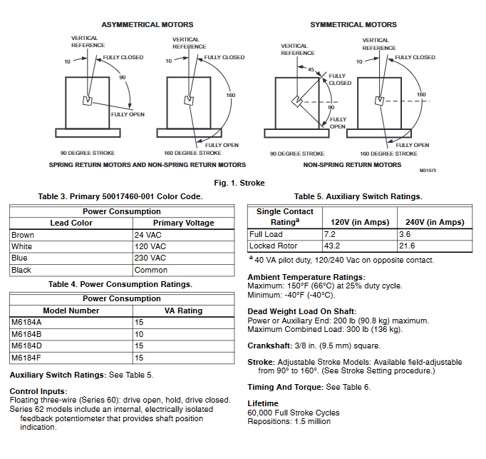
All models are double ended shafts (with slotted tapping at both ends), equipped with auxiliary switch cam, die cast aluminum shell, 90 ° -160 ° stroke adjustable on site, and fixed torque in the full voltage range;
The standard timing is 30 seconds (90 ° stroke)/60 seconds (160 ° stroke), and other timing options can be customized. The TRADELINE model comes with standardized selection packaging, which is consistent with the standard specifications.
Lifespan and Certification
Mechanical lifespan: 60000 full stroke cycles, 1.5 million resets;
Certification: UL listed (File No. E4436), CSA certification, US patent in the application stage;
Regional Description: Limited models are only available in Europe, please consult your local agent.
Core technical specifications
1. Electrical and physical specifications
Specific parameters of specification items
Working voltage 24Vac (50/60Hz), transformer can be pre installed in the factory/installed on site
Power consumption M6184A/D/F: 15VA; M6184B:10VA
Auxiliary switch rated 120V: Full load 7.2A, locked rotor 43.2A; 240V: Full load 3.6A, locked rotor 21.6A (reverse contact 40VA pilot load)
The crankshaft specification is 3/8in (9.5mm) square, and all models are double ended shafts
Maximum single end load limit for power end/auxiliary end: 200lb (90.8kg); Comprehensive maximum: 300lb (136kg)
Minimum ambient temperature: -40 ° F (-40 ° C); Maximum: 150 ° F (66 ° C) (25% load cycle)
Lead color code brown: 24Vac; White: 120Vac; Blue: 230Vac; Black: Public end
2. Timing and torque specifications
The starting torque of this series of motors is twice the normal operating torque, and is only used to overcome sudden large loads such as air door/valve jamming. Long term operation with starting torque is prohibited; The timing of the 300lb in torque motor is 2/4 minutes, and stalling may damage the drive shaft. The torque is the sum of the torque of both end shafts, and the specific parameters are as follows:
90 ° stroke timing (s) 160 ° stroke timing (s) normal operating torque (lb in/N · m) - reset spring normal operating torque (lb in/N · m) - no reset spring starting torque (lb in/N · m) - reset spring starting torque (lb in/N · m) - no reset spring
15 30 75(8.5) 150(17.0) - -
30 60 60(6.8) 35(4.0) 120(13.6) 70(7.9)
- - - 150(17.0) - 300(34.0)
60 120 - 300(34.0) - 600(68.0)
120 240 150(17.0) 300(34.0) - -
3. 62 series feedback potentiometer specifications
The 62 series feedback potentiometer is divided into two types: * * - S (non-linear, suitable for 90 series driven) and - F (0-10 K-line) * *, both of which can be used as voltage dividers. The feedback resistor is cut off with the stroke angle. The 160 ° motor is the full range, and the 90 ° asymmetric motor takes the first half and the symmetric motor takes the middle section. The core characteristics are as follows:
Voltage output: The TG terminal of the 160 ° motor outputs 4-96% of the YG terminal input, while the asymmetric terminal outputs 4-56% and the symmetric terminal outputs 24-76% at 90 °. The TY terminal outputs the reverse signal;
Diverting resistor: The driven 90 series motor requires a 142 Ω full stroke feedback resistor, which is matched with 187/274 Ω shunt resistors according to the model. The - F model does not have a suitable shunt resistor;
Resistance reading: Due to circuit protection, it is not possible to directly read the resistance, and the axis position needs to be tested through a voltage divider.
Model Naming Rules
This series of motor models consists of M+series+torque/reset+structure+auxiliary switch+suffix, and the core coding rules are as follows (taking M6184AXXXX as an example):
First place: M (motor);
Second and third digits: 61/62 (series, 62 with feedback);
Fourth position: 8 (60lb in reset spring/150lb in no reset), 9 (300lb in no reset);
Fifth position: 2 (double end axis normally closed reset), 4 (no reset), 5 (normally closed reset);
Sixth position: A/D (0 auxiliary switches), B/E (1 auxiliary switch), C/F (2 auxiliary switches);
Suffixes: - S (non-linear feedback), - F (linear feedback).
Supporting accessories
This series of motors provides a full range of accessories, covering switch, adapter, connecting rod, protection, power supply and other needs. The core accessories and functions are as follows:
Auxiliary switch/potentiometer: 220736A (single switch)/220736B (dual switch) built-in kit (on-site installation); Q607 external auxiliary switch; Q181 auxiliary potentiometer (controls 1-4 90 series motors);
Adapter/crank arm: 220738A (shaft height increased by 3/4in, matching old model); 220741A (quick connect terminal to screw terminal); 221455A/7617ADW adjustable crank arm (can rotate downwards, no adapter required);
Transformer: 50017460-001 (24/120/230Vac input), 50017460-003 (120Vac input), both with 24Vac output;
Connecting rod/bracket: Q605 damper connecting rod (including crank arm); Q5001 water/steam valve connecting rod assembly; Q100 butterfly valve connecting rod (220738A required);
Protective accessories: 4074ERU waterproof kit (achieving NEMA 3 protection when not installed upright); ES650-117 explosion-proof shell (explosive environment, 7617DM coupling required, valve connecting rod not compatible);
Installation and wiring specifications
Basic installation requirements
Construction personnel: Professional trained technicians are required to disconnect all power sources before construction (motors with auxiliary switches may have multiple disconnection points);
Mechanical installation: The crankshaft must be installed horizontally, and the flange should be fitted with 1/4-inch machine screws/bolts; The factory ships motors without reset springs in the normally closed position (counterclockwise limit when viewed from the power end);
Environmental requirements: Keep away from acid mist and corrosive vapors; Use zinc/cadmium plated fasteners (stainless steel/brass prohibited) in high salt environments, paired with 220738A adapter;
Space requirements: Reserve space for accessory installation and maintenance. Liquid tight conduit joints are required for outdoor installation, and 4074ERU waterproof kits are required for non upright installation.
Adapter usage scenarios
220738A shaft height adapter is the core installation accessory, and must be used in scenarios such as Q607 external auxiliary switch, air door linkage requiring downward rotation/sufficient stroke, and all valve linkages except Q5001; Q5001 valve connecting rod does not require an adapter.
Wiring specifications
Compliance with local electrical regulations is required. When multiple motors are connected in parallel, the VA value of the power supply must meet all motor loads to avoid overload;
The motor terminal is a quick connect terminal on the top of the circuit board, and four screws in the junction box need to be removed before wiring;
Reverse rotation: Swap the W/B terminals for the 61 series, and swap the 1/2 terminals (motor rotation) and Y/G terminals (maintaining feedback synchronization) for the 62 series;
Transformer wiring: It is necessary to ensure that L1 corresponds to motor 4 terminals and L2 corresponds to motor 3 terminals to avoid reverse connection.
Core adjustment operation
Before all adjustment operations, the controller must be disconnected and the connecting rod must be removed. For motors with built-in transformers, only the power connection should be retained. It is forbidden to rotate the motor shaft by hand/wrench (which may damage the gear system and stroke limit contacts).
Stroke adjustment
61 series: From the power end perspective, the stroke potentiometer is located on the far left, with a clockwise full rotation of 160 ° and a counterclockwise full rotation of 90 °, with the middle position being the middle stroke;
62 series: Left stroke potentiometer and right sensitivity potentiometer, both potentiometers rotate synchronously, clockwise full 160 ° and counterclockwise full 90 °.
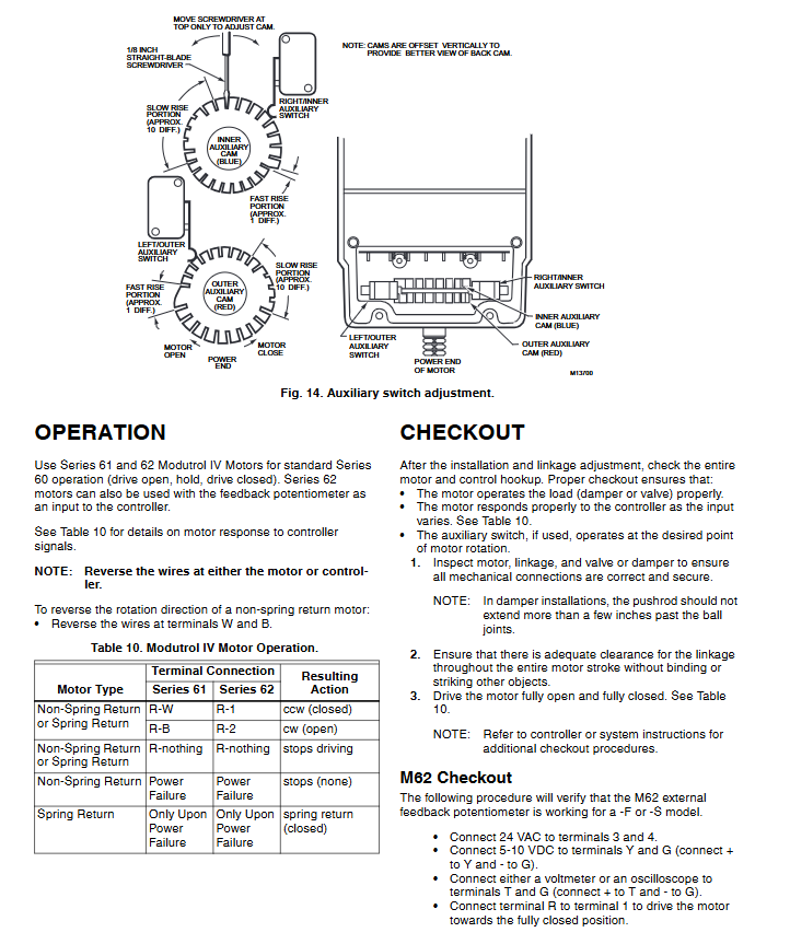
Auxiliary switch adjustment
The auxiliary switch is driven by an adjustable cam and supports 1 °/10 ° differential. The factory defaults to 30 ° on and 1 ° differential. Switching between different differential modes will cause the switch action to reverse. Adjustment steps:
Remove the junction box cover, disconnect the controller, and drive the motor to the auxiliary equipment action position;
1 ° Differential: Check the R-B contact for continuity. If it is open, turn the cam clockwise to close, and if it is closed, turn counterclockwise to disconnect;
10 ° Differential: Rotate the reset spring cam 180 ° to check the continuity of the R-B contact. If it is open, turn counterclockwise to close, and if it is closed, turn clockwise to disconnect;
Test the full stroke action, reset the controller and junction box cover.
62 series feedback potentiometer adjustment
Linear feedback: When there is no shunt resistor, the potentiometer directly outputs a linear signal of the shaft position;
90 series passive: A shunt resistor needs to be installed between the Y/G terminals to achieve a 142 Ω full stroke feedback resistor, with the resistor model referenced in Table 2;
Test: It is not possible to directly measure the resistance, and 5-10VDC needs to be applied through a voltage divider to test the linear change of the TG terminal voltage.
62 series driven control (multi motor synchronous)
The 62 series * * - S model * * can achieve passive control of 90 series motors. It is recommended that the number of slave stations should not exceed 6. Core specifications:
Motor matching: All driven motors must be of the same symmetrical/asymmetrical type;
Resistance configuration: Install shunt resistors according to the number of slave stations. One unit does not require a resistor, two units have 3500 Ω, three units have 2000 Ω, and six units have 800 Ω (symmetrical 90 ° stroke uses 5000/2400/1200 Ω, etc.);
Wiring rules: Connect one resistor to each of the T-G and T-Y terminals of the main motor 62 series; Connect one resistor to each R-B and R-W end of the 90 series substation;
Potentiometer setting: Adjust the stroke/sensitivity potentiometer (clockwise CW/counterclockwise CCW) according to the master/slave station stroke and symmetry type. It is not recommended to set it from 90 ° stroke to 160 ° stroke.
Replacement, Inspection, and Debugging
Replacement process
Wind door application: power off to dismantle old motor → determine adapter requirements (if the connecting rod is accessible and there is no jamming, no need) → directly install/match 220738A → install crank arm and connecting rod → debug;
Valve application: Q100/Q601/Q618 connecting rods require adapters, Q5001 does not require them → Honeywell V5011 (two-way)/V5013 (three-way) valves must use a 160 ° stroke motor → After installation, test the full stroke.
Inspection and debugging
Routine inspection: Check the firmness of mechanical connections → Test the full stroke of the motor for no jamming, and the connecting rod for no collision → Auxiliary switch accurately operates at the set position → Reset the spring type power-off verification for automatic return;
62 series special inspection: 3/4 terminal connected to 24Vac → Y/G terminal connected to 5-10VDC (Y+G -) → T/G terminal connected to voltmeter/oscilloscope → Drive motor full stroke, verify voltage linear change (160 °: 5-95% Vin, 90 ° asymmetric: 5-55% Vin, symmetric: 25-75% Vin);
Old model replacement: The motor that was originally connected to the R927C/R9107A relay is recommended to remove the relay and replace it directly with a 90 series Modutrol IV motor.
- YOKOGAWA
- Reliance
- ADVANCED
- SEW
- ProSoft
- WATLOW
- Kongsberg
- FANUC
- VSD
- DCS
- PLC
- man-machine
- Covid-19
- Energy and Gender
- Energy Access
- Renewable Integration
- Energy Subsidies
- Energy and Water
- Net zero emission
- Energy Security
- Critical Minerals
- A-B
- petroleum
- Mine scale
- Sewage treatment
- cement
- architecture
- Industrial information
- New energy
- Automobile market
- electricity
- Construction site
- HIMA
- ABB
- Rockwell
- Schneider Modicon
- Siemens
- xYCOM
- Yaskawa
- Woodward
- BOSCH Rexroth
- MOOG
- General Electric
- American NI
- Rolls-Royce
- CTI
- Honeywell
- EMERSON
- MAN
- GE
- TRICONEX
- Control Wave
- ALSTOM
- AMAT
- STUDER
- KONGSBERG
- MOTOROLA
- DANAHER MOTION
- Bentley
- Galil
- EATON
- MOLEX
- Triconex
- DEIF
- B&W
- ZYGO
- Aerotech
- DANFOSS
- KOLLMORGEN
- Beijer
- Endress+Hauser
- schneider
- Foxboro
- KB
- REXROTH
- YAMAHA
- Johnson
- Westinghouse
- WAGO
- TOSHIBA
- TEKTRONIX
- BENDER
- BMCM
- SMC
- HITACHI
- HIRSCHMANN
- XP POWER
- Baldor
- Meggitt
- SHINKAWA
- Other Brands
- UniOP
- KUKA
- IBA
- Beckhoff
-
ADLINK CPCI-6860A - 51-31310-OB10 industrial motherboard CompactPCI SBC
-
ADLINK AmITX-SL-G-H110 - 51-7A104-0A30 Mini-ITX Industrial Motherboard
-
ADLINK PXI-2005-003 - CPCI Industrial PC Data Acquisition Card Multi-Function DAQ
-
ADLINK DININ-814M - 51-14032-0A3D SCSI-100P cable connection Interface Terminal Board
-
ADLINK CPCI-3920NA/C2D15/M1G - 3U CompactPCI Intel Core 2 Duo Single Board Computer
-
ADLINK PCIE-8560 - 51-18014-0A20 Communication Card High Speed DAQ
-
ADLINK PCI-C154+ - Motion Control Card 4-axis Motion Controller Board
-
ADLINK PCI-RTV24 - image capture card Analog Video Frame Grabber
-
ADLINK NuPRO-842LV/P - 51-41360-0B30 Industrial Motherboard CPU Board
-
ADLINK cBP-3208/3208R - CPCI Board 3U 8-Slot CompactPCI Backplane
-
ADLINK PCI-8164 - 4-Axis Motion Controller PCI Card 51-12406-0A40
-
ADLINK PCIe-GIE64+ - 4-CH GigE Vision PoE+ Frame Grabber Video Capture Card
-
ADLINK CPCI-6860 / 6860A - CompactPCI Dual Xeon Single Board Computer
-
ADLINK IEC-915GV - REV 1.1 Industrial motherboard CPU Board
-
ADLINK ND-6520 - Technology RS-232 to RS-422RS-485 Converter NuDAM Module
-
ADLINK RTV-24 / PCI-MP4S - 51-12519-1C30 4-Channel Real Time Video Capture Board
-
ADLINK cPCI-6910 / cPCI-6910AM/M1G - cPCI-6910AM/DXL16/M1G/S80G(G)-3120 BOARD CompactPCI SBC
-
ADLINK NUPRO-A40H - Linghua 51-41807-1A30 Industrial Control Computer Motherboard
-
ADLINK USB-3488A - USB to GPIB INTERFACE USB-3488A(G) Controller Module
-
ADLINK PCI-8134A - motion control card 4-Axis Controller Card
-
ADLINK PCI-7432 - Board 32-Channel input / 32-output Isolated Digital I/O PCI Card
-
ADLINK PCI-8134A - 51-12421-0A10 motion controller card tested
-
ADLINK LPCIe-7230 - 32 CH Isolated Input/output Card 2 Interrupts Low Profile PCIe
-
ADLINK NuPRO-E340 - industrial computer motherboard 51-47807-0A30 PICMG 1.3 SHB
-
ADLINK PCI-7434 - High-speed Digital Acquisition Card 64-CH Isolated DO Card
-
ADLINK NuPRO-E330 - 51-41805-0A20 Indsutrial Board SHB Single Board Computer
-
ADLINK PCI-7248 - OPTO-22 48 CHANNEL DIO DIGITAL TTL/DTL I/O 51-12006-0A40 GP
-
ADLINK PCI-8134 - Motion control card 4-Axis Controller Card
-
ADLINK AMP-208C - Movimiento Control Tarjeta 51-12420-1A20 W/Expansión & Breakout
-
ADLINK PCI-8164 - 51-12406-0A40 PCB Board 4-Axis Motion Controller Card
-
ADLINK DIN-68Y-SGII / DIN-68M-J3A - Terminal Board Connector Interface Block
-
ADLINK PCIe-7432 - Technology 51-18402-0A10 PCIe Card With High Input Range
-
ADLINK PCI-8144 / PCI-8144N - Motion control card 4-Axis Stepper Controller Card
-
ADLINK HSL-HUB3/REPEATER - HIGH SPEED LINK EXTENSION MODULES Distributed Hub Module
-
ADLINK ND-6017 - Data Logging + Acquisition 8CH A/D input Mod NuDAM Module
-
ADLINK LPCIe-7250 - data acquisition card Low Profile 8-CH Relay Output Card
-
ADLINK PCI-7432 - I/O card 64-CH Isolated Digital Input Output PCI Card
-
ADLINK IMB-M43H - industrial control computer motherboard Q87 Chip Micro-ATX
-
ADLINK MP-C154 - Motion control Card 4-Axis Motion Controller Board
-
ADLINK PCI-RTV24 - image capture card Video Frame Grabber Card
-
ADLINK PCI-7250 - 8-CH Relay Output & 8-CH Isolated DI Card
-
ADLINK PCI-6308V - 8-CH 12-Bit Isolated Analog Output PCI Card PCB-I-E-1148=6EX2
-
ADLINK PCI-7248 - capture card 48-CH Opto-22 Compatible DIO Card
-
ADLINK HSL-AI16A02-M-VV - Analog Input Output Distributed Module
-
ADLINK NuPRO-A301 - Rev:1.4 NUPRO-A301 PICMG Full-Size Single Board Computer
-
ADLINK PCI-6208V-GL - 8-CH Voltage Analog Output PCI Card
-
ADLINK PCI-8134A - 51-12421-0A10 4-Axis Motion Controller Card
-
ADLINK MNET-S23 - TECHNOLOGY MNET S23 - SERVO DRIVER CONTROL MODULE
-
ADLINK M-342 - ATX I3 I5 I7 Q67 Industrial Motherboard
-
ADLINK NUPRO-780 - Industrial Motherboard CPU Board PICMG SBC
-
ADLINK MP-C154 / MP-C152 - 4-Axis Motion Control Card Pulse-Train Controller
-
ADLINK NuPRO-935A/LV10B0 - Motherboard 51-41802-0A10 GP w/RAM Industrial Control Board
-
ADLINK MP-C154 - Motion control card 4-Axis Motion Controller Mainboard
-
ADLINK PCI-7250 - PCI Acquisition Card 8-CH Relay Output Isolated DI Card
-
ADLINK ACL-7124 - Technology Inc.24 DIO Card Digital Input Output Card
-
ADLINK PCI-8554 A2 - Timer/Counter Data Acquisition Card
-
ADLINK DIN-825-GP4 - Terminal Block Interface Board Breakout Module
-
ADLINK NuPR0-761 - REV:1.1 Industrial motherboard Full-Size PICMG SBC
-
ADLINK MXE-1401/M8G (G) - Matrix Fanless Embedded Computer Industrial PC
-
ADLINK HSL-DI16DO16-UD-NN - Digital 16 Channel I/O Mod Distributed I/O Module
-
ADLINK ND6520 - NUDAM INTELLIGENT DA&C MODULE RS232-RS-422/RS485 CONVERTOR
-
ADLINK NUPRO-761 - REV:1.1 Industrial Motherboard CPU Board
-
ADLINK AMP-208C - Motion Control Card 51-12420-1A20 DSP-based 8-axis
-
ADLINK NuPRO-A301REV 1.4 - with packaging industrial computer motherboard PICMG SBC
-
ADLINK PCM-9112+ - 51-12300-0A2 industrial motherboard Multi-Function DAQ PC/104 Module
-
ADLINK PCM-7250+ - 8-CH Relay Outputs & 8-CH Isolated DI Module PC/104
-
ADLINK PCI-RTV24 - Image capture card Analog Video Frame Grabber
-
ADLINK PCI-8134 - Motion Controller PCI Card 4-Axis Controller Board
-
ADLINK PCI-7432 - Isolated Digital I/O PCI Card
-
ADLINK PCI-8554 A2 - acquisition card Timer/Counter Card
-
ADLINK PCI-8132 - Rev.A2 2-Axis Servo & Stepper Motion Controller Card
-
ADLINK PCI-8132 - Data Acquisition card 2-Axis Motion Controller Card
-
ADLINK EBP-13E4 - 51-46703-0A30 Industrial Backplane Board Passive Backplane
-
ADLINK PCI-800L - Electronic Card Interface Controller Card
-
ADLINK PCIe-GIE72 - 51-18531-0A10 PCB Board GigE Vision Frame Grabber
-
ADLINK DAQ-2010(G)-OOBO - Simultaneous-Sampling Multi-Function DAQ Card
-
ADLINK PCI-9112 - REV.B1 Multifunction DAQ Card Data Acquisition Card
-
ADLINK PCI-7230 - 51-12003-DA60 32-CH Isolated Digital I/O Card
-
ADLINK PCI-7432 - Data Acquisition Card Isolated Digital I/O PCI Card
-
ADLINK ETX-AT-N270-18/LXE - 51-71111-0A20 ETX CPU Module Motherboard
-
ADLINK HSL-DI32-UD-N - DIGITAL INPUT 32 POINTS MODULE Distributed I/O
-
ADLINK AMP-204C - Motion Control card DSP-Based 4-Axis Advanced Controller
-
ADLINK MNET-4XMOG-0050 - Four-axis Motion Controller Distributed Motion Module
-
ADLINK AMP-204C - Motion control card DSP-Based 4-Axis Pulse-Train Controller
-
ADLINK PCI-7442 - Switch card 64-Channel Datalogging & Acquisition Card
-
ADLINK M-302 - Industrial control motherboard ATX PC Board
-
ADLINK NUPRO-852 / NUPRO-852LV - Industrial motherboard Single Board Computer
-
ADLINK PCI-8134 - REV.B1. 4-Axis Motion Controller Card
-
ADLINK PCI-GIE62 + - 51-18502-0A20 2-CH GigE Vision Frame Grabber PoE Card
-
ADLINK PCI-MPG24 - 51-12523-0B20 MPEG4 Card Video Compression Hardware
-
ADLINK HSL-TB32-M-DIN - 32-CH I/O TERMINAL W/ HSL-AI16AO2-M-VV MODULE
-
ADLINK PCI-M114-GL - PCB Ver 2.1 Motion Controller Axis Card
-
ADLINK IMB-M40H - SYM76996H61 motherboard Industrial Computer Mainboard
-
ADLINK NUPRO-A40H - 51-41807-1A20 industrial control motherboard H61 Chip
-
ADLINK PCI-M114-GL - Axis Card Data Acquisition Card PCB VER2.2 Motion Controller
-
ADLINK PCI-8134 - Motion Controller PCI Card 4-Axis Controller Board
-
ADLINK PCI-8102 - Motion control card 2-Axis Servo & Stepper Controller
-
ADLINK NuPRO-841REV:3.0 - motherboard Industrial Control PC Board
-
ADLINK HSL-TB32-U-DIN REV A1 - Breakout Terminal Board Field I/O Module
-
ADLINK AMP-204C - Motion Control card DSP-Based 4-Axis Pulse-Train Controller
-
ADLINK NUPRO-A40H - 51-41807-1A20 industrial control motherboard H61 PC Board
-
ADLINK PCI-6308A / PCI-6308V - 51-12202-0A50 Isolated Analog Output Card
-
ADLINK AMP-204C - DSP-Based 4-Axis Advanced Pulse-Train Motion Controller
-
ADLINK PCI-7434 - Technology 64-Channel Isolated Digital I/O PCI Cards
-
ADLINK CPCI-6840 / CPCI-6840V / PM16/M1G-12G0 - CompactPCI Single Board Computer CPU Module
-
ADLINK PCIE-GIE74 - Motherboard Video Capture Card 51-18531-0A10 Frame Grabber
-
ADLINK NuPRO-E330 - industrial computer equipment motherboard Control Mainboard
-
ADLINK AMP-208C / 51-12420-1A20 - Motion Control Card W/ Expansion & Breakout Board
-
ADLINK HPCI-14S12U - industrial computer baseboard Passive Backplane 14 Slots
-
ADLINK PCI-8164 - 4-Axis Motion Controller PCI Card W/ 1x Cable, 1x Breakout Box
-
ADLINK PCIe-RTV24 - 51-18016-0A20 Image Acquisition Video Capture Card
-
ADLINK M-342 - 5 PCI ATX Motherboard Industrial PC Mainboard
-
ADLINK PCI-FIW64 - 4/2 Channel IEEE1394B Image Capture Card FireWire Frame Grabber
-
ADLINK PCI-7432 - digital IO card 64-CH Isolated Digital Input Output Card
-
ADLINK 51-12001-0C20 - Circuit Board PCI-7200 Data Acquisition Controller Card
-
ADLINK PXI-3920 - PXI 3U cPCI Industrial Controller Embedded System CPU Board
-
ADLINK NuPRO-841REV:2.0 - motherboard Industrial Control PC Board
-
ADLINK NuPro-E330 - 51-41805-0A20 PCB Industrial Control Computer Motherboard
-
ADLINK PCI-RTV24 - Image capture card Analog Video Frame Grabber
-
ADLINK PCI-7442 - Switch card 64-Channel Datalogging & Acquisition Card
-
ADLINK HPX-13S4 - device baseboard Passive Backplane Riser Card
-
ADLINK PCI-9112 REV A.1 - Multi Function DA&C Board Data Acquisition Card
-
ADLINK PCI-7248 - 51-12006-0A40 Card Control 48-CH Digital I/O Module
-
ADLINK CPCI-6860 / 6860A - motherboard CompactPCI Dual Xeon Single Board Computer
-
ADLINK DPAC-3020-11(G) - Embedded PC Automation Controller Machine Control Board
-
ADLINK NuPRO-841 REV:1.0 - industrial control motherboard CPU Board
-
ADLINK MNET-4XMOG-0050 - Four-axis Motion Controller MNET Motion Control Card
-
ADLINK ETX-AT-N270-18/LXE - 51-71111-0A20 ETX CPU Module Motherboard

K-JIANG

Add: Jimei North Road, Jimei District, Xiamen, Fujian, China
Tell:+86-15305925923