
K-WANG


Emerson Micro Motion High Precision HPC010/HPC015 Series High Pressure Coriolis Flow Meter Installation Guide
Emerson Micro Motion High Precision HPC010/HPC015 Series High Pressure Coriolis Flow Meter Installation Guide
Installation preparation and environmental requirements
(1) Pre installation checklist
Installation in hazardous areas: Confirm that the certification label level matches the environment;
Temperature compliance: The process medium and ambient temperature are within the equipment limit range;
Flow direction alignment: The flow direction arrow on the sensor housing is consistent with the actual fluid flow direction;
Component matching: Extended core processors correspond one-to-one with sensors.
(2) Key environmental parameters
Restriction type HPC010 HPC015 Remarks
Process medium temperature -50 ℃~125 ℃~46 ℃~200 ℃ Hazardous area certification may have stricter restrictions
Environmental temperature -40 ℃~60 ℃ -40 ℃~60 ℃ Electronic components need to be installed separately if they exceed the range
Vibration limit 5-1000Hz, ≤ 0.35g RMS 5-2000Hz, ≤ 1.0g. When exceeding the limit, anti vibration clamps need to be installed
(3) Best practices for installation
Straight pipe section: No upstream/downstream straight pipe section is required, it can be installed directly;
Pipeline installation:
Vertical pipeline: Liquid/slurry flows upward from bottom to top, gas flows downward;
Block valve: installed downstream of the sensor to avoid fluid backflow affecting the measurement;
Load control: Avoid transmitting bending/twisting loads of pipelines to sensors, without relying on sensors to adjust pipeline alignment;
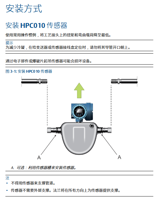
Support requirement: The sensor does not require external support, and the flange provides all-round support.
Core installation operation
(1) Sensor installation
HPC010 sensor: Use the sensor's built-in slot for installation. Do not lift it with electronic components or rupture discs to avoid damaging the equipment;
HPC015 sensor:
Basic installation: Directly fix process joints to minimize torque and bending loads;
Optional installation: Wall mounted through brackets or installed with 2 U-bolt pipes.
(2) Installation of electronic components
Enhanced Core Processor:
Direction adjustment: Loosen the 4 fixing screws, rotate the bracket to the desired direction, and tighten the torque to 3-4Nm;
Fixed method: Instrument column/wall installation, pipeline installation requires self provided U-bolts.
MVD Direct Connect intrinsic safety barrier:
Installation: Buckled onto a 35mm DIN rail, with the bottom locking device removed;
Fixed: The end clamping device is tightly attached to the safety barrier and fixed by tightening the screws.
(3) Extended electronic component connection
Cleaning requirements: Keep the extension tube and through tube clean and dry to avoid moisture/impurities damaging electronic components;
Connection steps:
Remove the plastic cap/plug and keep the O-ring on the through tube;
Align the extension tube with the through tube slot, and close the clamp after inserting it;
Tighten the clamp screw to a torque of 1.47-2.03Nm.
Wiring configuration specifications
(1) Classification of wiring options
Reference document for wiring requirements of electronic component options
Integrated transmitter sensor and transmitter pre connected, wiring free transmitter installation manual
Extended electronic components with physical and electrical connections, no additional wiring required. Section 3.5 of this manual
MVD Direct Connect without transmitter, sensor directly connected to host, high-precision MVD Direct Connect instrument manual
The split core processor+transmitter core processor is pre connected to the sensor and requires a 4-wire cable to connect the transmitter. Section 4.2 of this manual
(2) 4-wire cable wiring
cable specifications
Gaozhun provides: shielded/armored type, including power supply (red/black, 0.823mm ²), RS-485 (white/green, 0.326mm ²);
User provided: Twisted pair structure, in compliance with hazardous area requirements, with wire diameter and length matching as follows:
Wiring Function Wire Diameter (mm ²) Maximum Length (m)
Power supply (VDC) 0.326 91
Power supply (VDC) 0.518 152
Power supply (VDC) 0.823 305
Signal (RS-485) ≥ 0.326 305
Wiring steps:
Peel off the sheath (NPT connector 114mm, M20 connector 108mm);
Shielding layer treatment (NPT over 19mm, M20 over 13mm), wrapped with shielding wire for fixation;
Terminal connections: 1 (+VDC), 2 (- VDC), 3 (A-Com), 4 (B-Com);
Cover fixation: Aluminum shell 1.13-1.47Nm, stainless steel shell ≥ 2.15Nm.
(3) 9-wire cable and safety barrier wiring
9-wire cable: wire according to color matching, fully insert the bare end into the terminal, no exposed cables, tighten and fix, and seal the shell;
MVD safety barrier wiring:
Intrinsic safety terminals (connected to core processor): 41 (- VDC), 42 (+VDC), 43 (RS-485 A), 44 (RS-485 B);
Non intrinsic safety terminals (connected to host/power supply): 11 (- VDC), 12 (+VDC), 13 (RS-485 A), 14 (RS-485 B);
Attention: The safety barrier shielding wire should not be connected properly. Multiple devices can share the same power supply (ensure sufficient power supply).
Key points of safety and maintenance
(1) Grounding specifications
Following standards: European IEC 60079-14 (Section 16.2.2.3/4), US Canada ISA 12.06.01;
Technical Requirements:
Wire: copper wire, wire diameter ≥ 2.08mm ²;
Impedance:<1 Ω, with wires as short as possible;
Connection: If the pipeline joint is grounded, the sensor will automatically ground. Otherwise, connect the grounding screw of the electronic component.
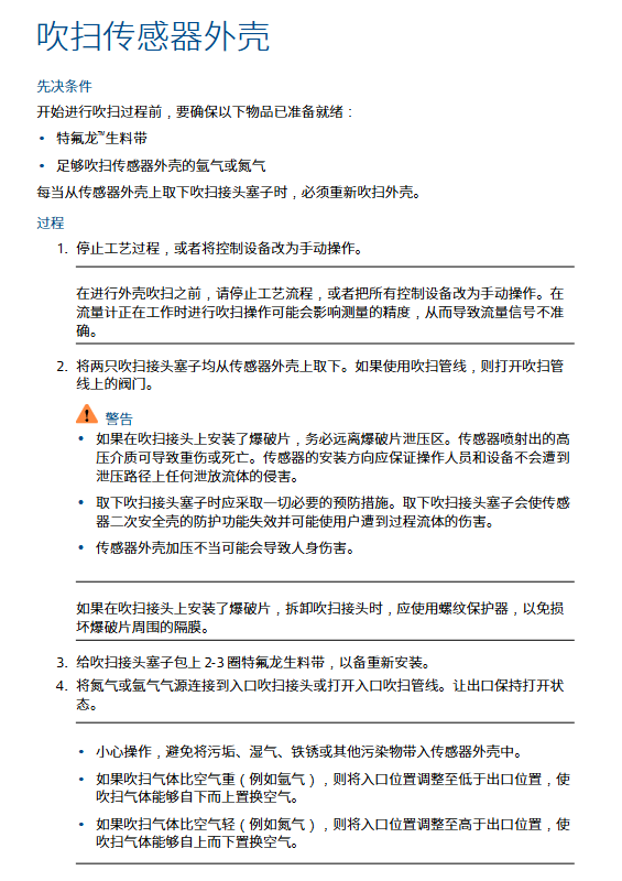
(2) Sensor shell blowing
Applicable scenario: After removing the plug of the blowing joint, it is necessary to blow it again;
Preparation items: PTFE raw material tape, argon/nitrogen gas;
Operation steps:
Stop the process or switch to manual control to avoid measurement errors;
Remove the blowing joint plug (away from the bursting disc pressure relief area);
Wrap the plug with 2-3 circles of raw material tape, and connect the air source to the inlet;
Blow gas flow direction: heavy gas flows from bottom to top, light gas flows from top to bottom;
Purging parameters: pressure ≤ 0.5bar, until air is completely replaced;
Sealing: Immediately seal the inlet/outlet with a plug after cutting off the gas source to avoid pressurization.
(3) Pressure relief protection
Explosive disc function: When the flow tube ruptures, release the process medium, and some users can connect the discharge pipeline;
Safety requirements:
Installation direction: Ensure that personnel/equipment are kept away from the pressure relief area to avoid injury from high-pressure fluid jets;
Maintenance: The bursting disc must always be installed and the flow meter should be stopped after damage;
Protection level: After modifying the blowing joint/blind plug/bursting disc, the IP66/IP67 level must be maintained.
- YOKOGAWA
- Reliance
- ADVANCED
- SEW
- ProSoft
- WATLOW
- Kongsberg
- FANUC
- VSD
- DCS
- PLC
- man-machine
- Covid-19
- Energy and Gender
- Energy Access
- Renewable Integration
- Energy Subsidies
- Energy and Water
- Net zero emission
- Energy Security
- Critical Minerals
- A-B
- petroleum
- Mine scale
- Sewage treatment
- cement
- architecture
- Industrial information
- New energy
- Automobile market
- electricity
- Construction site
- HIMA
- ABB
- Rockwell
- Schneider Modicon
- Siemens
- xYCOM
- Yaskawa
- Woodward
- BOSCH Rexroth
- MOOG
- General Electric
- American NI
- Rolls-Royce
- CTI
- Honeywell
- EMERSON
- MAN
- GE
- TRICONEX
- Control Wave
- ALSTOM
- AMAT
- STUDER
- KONGSBERG
- MOTOROLA
- DANAHER MOTION
- Bentley
- Galil
- EATON
- MOLEX
- Triconex
- DEIF
- B&W
- ZYGO
- Aerotech
- DANFOSS
- KOLLMORGEN
- Beijer
- Endress+Hauser
- schneider
- Foxboro
- KB
- REXROTH
- YAMAHA
- Johnson
- Westinghouse
- WAGO
- TOSHIBA
- TEKTRONIX
- BENDER
- BMCM
- SMC
- HITACHI
- HIRSCHMANN
- XP POWER
- Baldor
- Meggitt
- SHINKAWA
- Other Brands
- UniOP
- KUKA
- IBA
- Beckhoff
- ADLINK
-
Beckhoff CP6500-1012-0060 - Control Cabinet PC Interface Unit
-
Beckhoff FC5202-0000 - 2-Channel DeviceNet Master PCI Interface Card
-
Beckhoff CP6606-0001-0020 - 7-Inch Economy Panel PC Touch
-
Beckhoff CP2921-0010 - Multi-Touch Integrated Control Panel Display
-
Beckhoff CP7802-0001-0010 - 15-Inch Touch Screen Control Panel HMI
-
Beckhoff C6920-0050 - Control Cabinet Industrial PC
-
Beckhoff BK9105 - EtherNet/IP Bus Coupler Network Interface
-
Beckhoff 31 Modules - Bus Terminal Slice I/O Lot Assortment
-
Beckhoff CX2020-0120 - Embedded PC Basic CPU Module 8GB CFast Card
-
Beckhoff CP7001-0000 - HMI Control Panel Touch Screen
-
B&R 7EX484.50-1 - System 2005 Controller Base Module Slots
-
Beckhoff EK1322 - 2-Port EtherCAT P Extension Feed-In Terminal
-
Beckhoff CP6606-0001-0020 - 7-Inch Single-Touch Economy Panel PC
-
Beckhoff CP6607-0001-0000 - Economy Installation Operator Panel PC 5.7-Inch
-
Beckhoff AX5103-0000-0200 - Digital Compact Servo Driver 3 Phase
-
Beckhoff CP7802-0001-0010 - 15-Inch Touch Screen Control Panel
-
Beckhoff AX8620 - Power Supply Module Axis System
-
Beckhoff CX2030-0121 - Embedded PC Controller Module
-
Beckhoff CP6606-0001-0020 - 7-Inch Economy Panel PC Touch Screen
-
Beckhoff CX2030-0121 - Embedded PC CPU Module Windows Standard 7
-
Beckhoff BX3100-0000 - PROFIBUS DP Bus Terminal Controller
-
Beckhoff CX1020-0000 - Controller Set with Power Supply Unit
-
Beckhoff EK1100 - EtherCAT Coupler Terminal Module Set
-
Beckhoff CP7002-1043-0010 - HMI Display Panel with Control Panel Bracket
-
Beckhoff AM8031-0D10-0000 - Synchronous Servo Motor
-
Beckhoff CX5130-0175 - Embedded PC 4GB RAM Controller
-
Beckhoff CX5130-0155 - Embedded PC Automation Controller
-
Beckhoff C6930-0010 - Control Cabinet Industrial PC Core Duo
-
Beckhoff CP3924-0000 - Multi-Touch Control Panel Display
-
Beckhoff AM8023-0F20-0000 - Synchronous Servo Motor
-
B&R KL3362 - Bus Terminal Thermocouple Input Module
-
Beckhoff AL2006-0000-0000 - Linear Servo Motor Three Phase
-
Beckhoff CX5140-0155 - Embedded PC CPU Controller Module
-
Beckhoff FC9002 - Ethernet PCI Network Interface Card
-
Beckhoff CP7203-0021-0040 - Built-In Panel PC 19-Inch Touch Screen
-
Beckhoff C6930-0020 - Control Cabinet Industrial PC HDD CF Card
-
Beckhoff CX2900-0033 - Memory Card CFast Storage
-
Beckhoff CP6201-0001-0020 - Built-In Panel PC Display
-
b+m surface systems C6930-1121-0060 - Industrial PC Beckhoff Core i7
-
Beckhoff CP2221-0010 - Multi-Touch Built-In Panel PC
-
Beckhoff C6017-0010 - Ultra-Compact Industrial PC
-
Beckhoff FC5102-0000 - 2-Channel CANopen PCI Interface Card
-
Beckhoff CP7021-0000-0000 - HMI Control Panel Interface
-
Beckhoff CP2216-0020 - Multi-Touch Built-In Panel PC
-
Beckhoff C6140 - Industrial PC Tower System Pentium 4
-
Beckhoff AM3033-1E40 - Servo Motor with Gearbox Assembly
-
Beckhoff CX9020-0115 - Embedded PC CPU Controller Module
-
Beckhoff CP6809-0001-0000 - Built-In Control Panel HMI Terminal
-
Beckhoff CP3919-0000 - Multi-Touch Control Panel Touchscreen Monitor
-
Beckhoff AM8053-0LHB-0000 - Synchronous Servo Motor
-
Beckhoff C6920-1028-0000 - Control Cabinet Industrial Computer PC
-
Beckhoff CX1100-0014 - Power Supply Unit for CX1030
-
Beckhoff CX9001-0101 - Embedded PC CPU Controller Module
-
Beckhoff CP3916-1428-0000 - Control Panel Multi-Touch Monitor
-
Beckhoff CP7037-1027-0010 - HMI Built-In Control Panel PC
-
Beckhoff CX1020-0120 - CPU Module DVI USB Windows Standard
-
Beckhoff CX5020-0121 - Embedded PC Controller Module
-
Beckhoff EL5042 - 2-Channel Encoder Interface BiSS C EtherCAT Terminal
-
Beckhoff CP7201-0021-0040 - Built-In Panel PC Touch Monitor
-
B&R X20-RT-8401 - reACTION Technology Module I/O Block
-
Beckhoff CP2915-0010 - HMI Control Panel Display Touch Screen
-
Beckhoff EL7221 - Servomotor Cyber Terminal EtherCAT Module
-
Beckhoff CX5140-0175 - Embedded PC CPU Module
-
Beckhoff C6017-0010 - Ultra-Compact Industrial PC
-
Beckhoff CX2020-0130 - Embedded PC Basic CPU Module
-
Beckhoff CX1030-0011 - Basic CPU Module Windows CE 6.0
-
Beckhoff AM8043-1E00-0000 - Synchronous Servo Motor
-
Beckhoff CX1020-0110 - CPU Module Controller Interface Bundle
-
Beckhoff C6930-1069-0030 - Control Cabinet Industrial PC Mainboard CB3054-0001
-
Beckhoff KL9528 - Power Supply Terminal Module
-
Beckhoff AM8053-0K20-0000 - Synchronous Servo Motor
-
Beckhoff CX5020-1111 - Embedded PC Controller Module
-
Beckhoff CX5130-0175 - Embedded PC CPU Module Intel Atom
-
Beckhoff CP6401-1024-0040 - Husky Display Control Panel HMI Terminal
-
Beckhoff CP2616-0000 - Multi-Touch Display Automation Panel PC
-
Beckhoff CP7921-1075-0000 - 12-Inch HMI Control Panel ELO Touch
-
Beckhoff C6930-0060 - Control Cabinet Industrial PC SSD
-
Beckhoff AX5112-0000 - Digital Compact Servo Drive 3 Phase
-
Beckhoff C6930-0040 - Control Cabinet Industrial PC Intel Core i5
-
Beckhoff CP2616-0000 - Multi-Touch Display Automation Panel PC
-
Beckhoff KL1414 - 4-Channel Digital Input Bus Terminal
-
Beckhoff CX1020-0000 - Basic CPU Module Controller
-
Beckhoff CP6201-1008-0000 - 12-Inch Built-In Panel PC
-
Beckhoff CP7021-0000 - HMI Control Panel Display Screen
-
Beckhoff AX5106-0000 - Digital Compact Servo Drive
-
Beckhoff BX3100-0000 - Profibus DP Bus Terminal Controller
-
Beckhoff CP2916-0000 - Multi-Touch Built-In Control Panel
-
Beckhoff C6925-0030 - Fanless Control Cabinet Industrial PC
-
Beckhoff C6330 - Industrial PC Motherboard Boser HS6237 Celeron
-
Beckhoff AM3033-0C00-0000 - Synchronous Servo Motor
-
Beckhoff CP7232-0001-0030 - Control Panel PC HMI
-
Beckhoff CX5020-0122 - Embedded PC CPU Module
-
Beckhoff AM8043-0H10-0000 - Rotary Synchronous Servo Motor
-
Beckhoff CP3924-0010 - Multitouch Control Panel HMI
-
Beckhoff CX9020-0110-1005 - Embedded PC Basic CPU Module
-
Beckhoff BK9105 - EtherNet/IP Bus Coupler
-
Beckhoff CX1500-M310 - Profibus Master Fieldbus Extension Module
-
Beckhoff CX1500-M510 - PROFIBUS Master Fieldbus Extension Module
-
Beckhoff CP9922.0 - TTL-TX Display Transmitter Card
-
Beckhoff CP9010_1 - ISA Slot Interface Card
-
Beckhoff NRL75-DC30S15B - LCD Inverter Board
-
Beckhoff LTD121C30S - Toshiba LCD Display Panel
-
Beckhoff CP7732-1207-0030 - Operating Terminal Panel PC HMI
-
Beckhoff C5102-0010 - Rackmount Industrial Computer PC5000
-
Beckhoff C6015-0010 - Ultra-Compact Industrial PC
-
Beckhoff CB1056-0001 - Industrial PC Motherboard Mainboard
-
Beckhoff AX5103 - Digital Compact Servo Amplifier 1 Axis
-
Beckhoff AM8052-0J00-9000 - Rotary Synchronous Servo Motor
-
Beckhoff CP7932-0002-0000 - Control Panel HMI Display
-
Beckhoff CB1061-0001 - Industrial PC Motherboard Mainboard
-
Beckhoff C5102-0060 - 19-inch Rackmount Industrial PC
-
Beckhoff EL7342 - 2 Channel DC Motor Motion Interface EtherCAT Terminal
-
Beckhoff CX5120-0135 - Embedded PC CPU Module Intel Atom
-
Beckhoff CB1061-G4 - Industrial PC Motherboard Mainboard
-
Beckhoff CX50100121 - Embedded PC CPU Module
-
Beckhoff CX1030-0013-1002 - Basic CPU Module Intel Pentium M
-
Beckhoff CP7802-1075-0010 - Control Panel Touch Screen HMI
-
Beckhoff AM8023-0E20-0000 - Rotary Synchronous Servo Motor
-
Beckhoff EL5032 - 2 Channel Encoder Interface EnDAT EtherCAT Terminal
-
Beckhoff CX5130-0175 - Embedded PC CPU Module Intel Atom
-
Beckhoff CA4040-0000 - PCI Ethernet Network Board
-
Beckhoff C3340 - Panel PC Industrial Workstation
-
Beckhoff EL3068 - 8 Channel Analog Input EtherCAT Terminal 0-10V
-
Beckhoff EL1889 - 16 Channel Digital Input EtherCAT Terminal
-
Beckhoff C6640-0050 - Control Cabinet Industrial PC Intel Core i7
-
Beckhoff PC MIC 3230 TP - Industrial Panel PC Touch Screen
-
Beckhoff CX2040-0135 - Embedded PC Industrial CPU Module
-
Beckhoff CP6202-1020-0010 - Built-in Panel PC HMI

K-JIANG

Add: Jimei North Road, Jimei District, Xiamen, Fujian, China
Tell:+86-15305925923