
K-WANG


Honeywell IPC 620-06 Programmable Controller
Honeywell IPC 620-06 Programmable Controller
Product Infrastructure
Core positioning: IPC 620-06 is the core model of the 620 series programmable controller, designed specifically for industrial automation scenarios, with functions such as logic control, data acquisition, and equipment linkage, suitable for centralized or distributed control needs of small and medium-sized industrial devices.
hardware architecture
Rack type: processor rack (full rack: 620-0090/0091, 8 I/O slots; Half rack: 620-0092/0093, 4 I/O slots), I/O rack (full rack: 621-9990/9992, 12 I/O slots; Half rack: 621-9991, 6 I/O slots)
Installation specifications: Full rack compatible with 19 inch instrument rack (8 inches deep), half rack suitable for narrow spaces (10 inches wide), supports bidirectional installation of rack/panel
Core processor: Motorola 68B09E microprocessor, paired with 2K memory, supports EPROM optional expansion (27128 model)
Environment and Power Supply
|Category | Specification Parameters|
|Power supply type | AC (115/230VAC ± 10%), DC (24VDC ± 20%)|
|Frequency range | 47-63Hz|
|Working temperature | Industrial standard environment (unspecified, default 0-60 ℃)|
|Data backup | 3V lithium battery (AA lithium dry battery), backup for ≥ 6 months|
|Protective features | Rack mounted design, dust-proof modules, and anti misoperation terminal blocks|
Core Component Details
1. Processor module (PM: 620-0636)
Core configuration: 2K memory, including 768 bit output status table (0-191 actual I/O, 192-767 control relay), 256 16 bit registers (4096-4351)
Operation control: 3-position key switch (Program/Disable/RUN/Program), 4 status LEDs
RUN LED: Scan running indicator
FORCE LED: Command Force Status Indication
PASS LED: self-test pass indicator
BATTERY PASS LED: Battery normal indication
Backup and Expansion: Built in lithium battery compartment (front replaceable), supports EPROM program backup (U32 slot)
Communication interface: 9-pin D-type connector (RS4229600 Baud), connected to programming terminal/Loader
2. Power module (PSM)
Divided into processor rack power supply and I/O rack power supply, the core parameters are as follows:
Module Model Applicable Scenarios Input Specifications Output Specifications Key Features
620-0041 processor rack 115/230VAC+5VDC (8A), ± 15VDC (600mA) 95VA power consumption, 2A/1A fuse
620-0083 processor rack 85-132/170-250VAC+5VDC (15A), ± 15VDC (1.16A) 90W total power, switch selection
620-0046 processor full rack 20-28VDC+5VDC (8A), ± 15VDC (600mA) 96VA power consumption, 8A fuse
621-9932 I/O rack/processor half rack 20-28VDC+5VDC (8A), ± 15VDC (600mA) 96VA power consumption, 40A cold start current
621-9933 I/O rack 85-132/170-250VAC+5VDC (10-15A), ± 15VDC (1.3-2A) 110VA power consumption, 4A/2A fuse
621-9934 I/O rack/processor half rack 115/230VAC+5VDC (8A), ± 15VDC (600mA) single width module, 2A/1A fuse
3. I/O system
Rack configuration: The full rack supports 12 I/O modules, 1 PIOM, and 1 PSM; Half rack supports 6 I/O modules+1 PIOM+1 PSM
Module type:
Digital I/O: 8/16/32 points, voltage covers 5/12/24/48/115/230VAC/DC, supports Sink/Source type
Analog I/O: 8-point 4-20mA/0-10V input, 4-point 4-20mA/0-10V output, isolated design
Special features: thermocouple/mV input, high-speed counter, pulse input, ASCII communication, absolute encoder interface
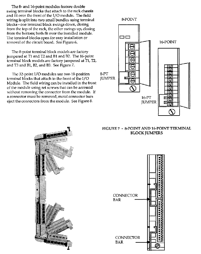
Terminal block design: The 8/16 point module adopts dual swing terminal blocks, and the 32 point module adopts dual 19 position terminal blocks, supporting on-site wiring with screw fixation
4. Expansion module
Module type, model, function positioning, key parameters
Control Network Module (CNM) 620-0038: Multiple PLCs can be interconnected up to 8 units, with 32/64 bit I/O status transmission
Communication Interface Module (CIM) 620-0043/0044/0048/0052 supports Modbus RTU, DMCS/ABC protocols for serial communication
Hiway Interface Module (HIM) - connects to TDC-3000 system to provide access interface for upper level devices
Operator Panel Interface (OPI) - Connect button/keyboard display single coaxial cable transmission
I/O Expansion Module (IOEM) 620-0053 Expansion I/O Rack 50 Pin D Connector, daisy chain topology
Parallel I/O module (PIOM) 621-9937 I/O rack controls 2 50 pin interfaces, with DIP switches configured for address configuration
Communication and Network
Parallel I/O link
Topology: daisy chain, processor rack IOEM → I/O rack PIOM → expansion I/O rack PIOM
Transmission distance: maximum 50 feet (multi conductor cable)
Capacity limit: Up to 2 external I/O racks, total system I/O points ≤ 192
Control Network
Transmission medium: twisted pair cable (up to 4000 feet), dual axis cable (up to 8000 feet)
Communication characteristics: High speed peer-to-peer communication, each PLC can transmit 32/64 bit I/O status and receive 256 bit I/O status
Response time: 8 PLCs with full service ≤ 18ms
Topology structure: multi-point configuration, supporting interconnection of 8 620 series PLCs
serial communication
Protocol support: CIM module provides Modbus RTU (620-0044), Honeywell DMCS (620-0048), ABC (620-0052) protocols
Interface standard: RS422/RS232, supports communication with 627 LOS and third-party smart devices
Operation mode and programming features
Three operation modes | Mode | Core function | Status indication | Key operation|
|Program | Program editing/uploading/downloading, do not scan program | RUN LED off | Clear/modify program, force command|
|DISABLE | Execute program without updating actual output | RUN LED stays on | Program testing, output status monitoring|
|RUN/PROGRAMME | switchable RUN/PROGRAMME, default RUN | RUN LED always on | normal control, online programming (ARMP)|
Programming Core Features
Instruction set: covering relay logic (NO/NC contacts, output, latch/unlock), timer/counter (ON/OFF delay, hold type), arithmetic operations (addition, subtraction, multiplication, division, comparison), data operations (Bring In/Send Out, PUSH/PULL), sequence control, etc., with a total of 30+instructions and execution time of 5.49-506.30 microseconds
ARMP online programming: firmware version ≥ 48 supported, program modification during operation, scan time increase ≤ 20ms, online programming DIP switch needs to be enabled
EPROM backup: supports writing RAM programs into EPROM, automatically restores when powered on (cold start/low battery), RAM programs cannot be modified
Mandatory function: Supports command enforcement, FORCE LED indication, requires activation through processor DIP switch
Data backup and recovery
Lithium battery backup: 3V AA lithium dry battery, backup memory/register data for ≥ 6 months, front replaceable
Cold start recovery: EPROM program → RAM, output status table reset, register data recovery
Hot start recovery: RAM program retention, output/register data retention, jump table not transferred
Diagnosis and safety features
Diagnostic function
Power on self-test (POST): microprocessor, ROM checksum, RAM read-write, I/O bus testing
Program checksum: Calculate the checksum for every 24 words scanned during operation, and compare it with the initial value to detect program errors
Online check: Check ISS instruction position, EOM instruction integrity, scan timeout (150-200ms)
Fault monitoring: The system status table (address 2413-2432) records scan loss, battery status, I/O fault count, and address
safety protection
Output fault handling: configured through PIOM DIP switch, output reset or hold in case of fault
Power protection: AC power undervoltage detection (115VAC ≤ 83V, 230VAC ≤ 166V), DC power undervoltage detection (24VDC ≤ 19V)
Static protection: Module insertion and removal require anti-static measures, as RAM data may be lost when the module is removed
Lithium battery safety: Do not charge, burn, short circuit, avoid high temperature storage
Address configuration and deployment
Address configuration rules
Rack start address: set through PIOM SW1, range 0-184, subsequent rack start address=previous rack end address+1
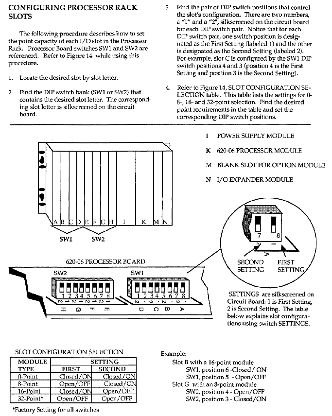
Slot address: Set through PIOM SW3/SW4/SW5, each slot can be configured with 0/8/16/32 points
Address example: Processor rack (0-127) → I/O rack # 1 (128-191), supports 8/16/32 point module hybrid configuration
Deployment requirements
Installation space: Reserved maintenance space around the full rack, half rack suitable for narrow environments such as motor control centers
Grounding requirements: The protective grounding and signal grounding should be separated, and the grounding resistance should be ≤ 4 Ω
Cable specification: Control Network uses shielded twisted pair cables, parallel I/O cable length ≤ 50 feet
- YOKOGAWA
- Reliance
- ADVANCED
- SEW
- ProSoft
- WATLOW
- Kongsberg
- FANUC
- VSD
- DCS
- PLC
- man-machine
- Covid-19
- Energy and Gender
- Energy Access
- Renewable Integration
- Energy Subsidies
- Energy and Water
- Net zero emission
- Energy Security
- Critical Minerals
- A-B
- petroleum
- Mine scale
- Sewage treatment
- cement
- architecture
- Industrial information
- New energy
- Automobile market
- electricity
- Construction site
- HIMA
- ABB
- Rockwell
- Schneider Modicon
- Siemens
- xYCOM
- Yaskawa
- Woodward
- BOSCH Rexroth
- MOOG
- General Electric
- American NI
- Rolls-Royce
- CTI
- Honeywell
- EMERSON
- MAN
- GE
- TRICONEX
- Control Wave
- ALSTOM
- AMAT
- STUDER
- KONGSBERG
- MOTOROLA
- DANAHER MOTION
- Bentley
- Galil
- EATON
- MOLEX
- Triconex
- DEIF
- B&W
- ZYGO
- Aerotech
- DANFOSS
- KOLLMORGEN
- Beijer
- Endress+Hauser
- schneider
- Foxboro
- KB
- REXROTH
- YAMAHA
- Johnson
- Westinghouse
- WAGO
- TOSHIBA
- TEKTRONIX
- BENDER
- BMCM
- SMC
- HITACHI
- HIRSCHMANN
- XP POWER
- Baldor
- Meggitt
- SHINKAWA
- Other Brands
- UniOP
- KUKA
- IBA
- Beckhoff
-
ADLINK CPCI-6860A - 51-31310-OB10 industrial motherboard CompactPCI SBC
-
ADLINK AmITX-SL-G-H110 - 51-7A104-0A30 Mini-ITX Industrial Motherboard
-
ADLINK PXI-2005-003 - CPCI Industrial PC Data Acquisition Card Multi-Function DAQ
-
ADLINK DININ-814M - 51-14032-0A3D SCSI-100P cable connection Interface Terminal Board
-
ADLINK CPCI-3920NA/C2D15/M1G - 3U CompactPCI Intel Core 2 Duo Single Board Computer
-
ADLINK PCIE-8560 - 51-18014-0A20 Communication Card High Speed DAQ
-
ADLINK PCI-C154+ - Motion Control Card 4-axis Motion Controller Board
-
ADLINK PCI-RTV24 - image capture card Analog Video Frame Grabber
-
ADLINK NuPRO-842LV/P - 51-41360-0B30 Industrial Motherboard CPU Board
-
ADLINK cBP-3208/3208R - CPCI Board 3U 8-Slot CompactPCI Backplane
-
ADLINK PCI-8164 - 4-Axis Motion Controller PCI Card 51-12406-0A40
-
ADLINK PCIe-GIE64+ - 4-CH GigE Vision PoE+ Frame Grabber Video Capture Card
-
ADLINK CPCI-6860 / 6860A - CompactPCI Dual Xeon Single Board Computer
-
ADLINK IEC-915GV - REV 1.1 Industrial motherboard CPU Board
-
ADLINK ND-6520 - Technology RS-232 to RS-422RS-485 Converter NuDAM Module
-
ADLINK RTV-24 / PCI-MP4S - 51-12519-1C30 4-Channel Real Time Video Capture Board
-
ADLINK cPCI-6910 / cPCI-6910AM/M1G - cPCI-6910AM/DXL16/M1G/S80G(G)-3120 BOARD CompactPCI SBC
-
ADLINK NUPRO-A40H - Linghua 51-41807-1A30 Industrial Control Computer Motherboard
-
ADLINK USB-3488A - USB to GPIB INTERFACE USB-3488A(G) Controller Module
-
ADLINK PCI-8134A - motion control card 4-Axis Controller Card
-
ADLINK PCI-7432 - Board 32-Channel input / 32-output Isolated Digital I/O PCI Card
-
ADLINK PCI-8134A - 51-12421-0A10 motion controller card tested
-
ADLINK LPCIe-7230 - 32 CH Isolated Input/output Card 2 Interrupts Low Profile PCIe
-
ADLINK NuPRO-E340 - industrial computer motherboard 51-47807-0A30 PICMG 1.3 SHB
-
ADLINK PCI-7434 - High-speed Digital Acquisition Card 64-CH Isolated DO Card
-
ADLINK NuPRO-E330 - 51-41805-0A20 Indsutrial Board SHB Single Board Computer
-
ADLINK PCI-7248 - OPTO-22 48 CHANNEL DIO DIGITAL TTL/DTL I/O 51-12006-0A40 GP
-
ADLINK PCI-8134 - Motion control card 4-Axis Controller Card
-
ADLINK AMP-208C - Movimiento Control Tarjeta 51-12420-1A20 W/Expansión & Breakout
-
ADLINK PCI-8164 - 51-12406-0A40 PCB Board 4-Axis Motion Controller Card
-
ADLINK DIN-68Y-SGII / DIN-68M-J3A - Terminal Board Connector Interface Block
-
ADLINK PCIe-7432 - Technology 51-18402-0A10 PCIe Card With High Input Range
-
ADLINK PCI-8144 / PCI-8144N - Motion control card 4-Axis Stepper Controller Card
-
ADLINK HSL-HUB3/REPEATER - HIGH SPEED LINK EXTENSION MODULES Distributed Hub Module
-
ADLINK ND-6017 - Data Logging + Acquisition 8CH A/D input Mod NuDAM Module
-
ADLINK LPCIe-7250 - data acquisition card Low Profile 8-CH Relay Output Card
-
ADLINK PCI-7432 - I/O card 64-CH Isolated Digital Input Output PCI Card
-
ADLINK IMB-M43H - industrial control computer motherboard Q87 Chip Micro-ATX
-
ADLINK MP-C154 - Motion control Card 4-Axis Motion Controller Board
-
ADLINK PCI-RTV24 - image capture card Video Frame Grabber Card
-
ADLINK PCI-7250 - 8-CH Relay Output & 8-CH Isolated DI Card
-
ADLINK PCI-6308V - 8-CH 12-Bit Isolated Analog Output PCI Card PCB-I-E-1148=6EX2
-
ADLINK PCI-7248 - capture card 48-CH Opto-22 Compatible DIO Card
-
ADLINK HSL-AI16A02-M-VV - Analog Input Output Distributed Module
-
ADLINK NuPRO-A301 - Rev:1.4 NUPRO-A301 PICMG Full-Size Single Board Computer
-
ADLINK PCI-6208V-GL - 8-CH Voltage Analog Output PCI Card
-
ADLINK PCI-8134A - 51-12421-0A10 4-Axis Motion Controller Card
-
ADLINK MNET-S23 - TECHNOLOGY MNET S23 - SERVO DRIVER CONTROL MODULE
-
ADLINK M-342 - ATX I3 I5 I7 Q67 Industrial Motherboard
-
ADLINK NUPRO-780 - Industrial Motherboard CPU Board PICMG SBC
-
ADLINK MP-C154 / MP-C152 - 4-Axis Motion Control Card Pulse-Train Controller
-
ADLINK NuPRO-935A/LV10B0 - Motherboard 51-41802-0A10 GP w/RAM Industrial Control Board
-
ADLINK MP-C154 - Motion control card 4-Axis Motion Controller Mainboard
-
ADLINK PCI-7250 - PCI Acquisition Card 8-CH Relay Output Isolated DI Card
-
ADLINK ACL-7124 - Technology Inc.24 DIO Card Digital Input Output Card
-
ADLINK PCI-8554 A2 - Timer/Counter Data Acquisition Card
-
ADLINK DIN-825-GP4 - Terminal Block Interface Board Breakout Module
-
ADLINK NuPR0-761 - REV:1.1 Industrial motherboard Full-Size PICMG SBC
-
ADLINK MXE-1401/M8G (G) - Matrix Fanless Embedded Computer Industrial PC
-
ADLINK HSL-DI16DO16-UD-NN - Digital 16 Channel I/O Mod Distributed I/O Module
-
ADLINK ND6520 - NUDAM INTELLIGENT DA&C MODULE RS232-RS-422/RS485 CONVERTOR
-
ADLINK NUPRO-761 - REV:1.1 Industrial Motherboard CPU Board
-
ADLINK AMP-208C - Motion Control Card 51-12420-1A20 DSP-based 8-axis
-
ADLINK NuPRO-A301REV 1.4 - with packaging industrial computer motherboard PICMG SBC
-
ADLINK PCM-9112+ - 51-12300-0A2 industrial motherboard Multi-Function DAQ PC/104 Module
-
ADLINK PCM-7250+ - 8-CH Relay Outputs & 8-CH Isolated DI Module PC/104
-
ADLINK PCI-RTV24 - Image capture card Analog Video Frame Grabber
-
ADLINK PCI-8134 - Motion Controller PCI Card 4-Axis Controller Board
-
ADLINK PCI-7432 - Isolated Digital I/O PCI Card
-
ADLINK PCI-8554 A2 - acquisition card Timer/Counter Card
-
ADLINK PCI-8132 - Rev.A2 2-Axis Servo & Stepper Motion Controller Card
-
ADLINK PCI-8132 - Data Acquisition card 2-Axis Motion Controller Card
-
ADLINK EBP-13E4 - 51-46703-0A30 Industrial Backplane Board Passive Backplane
-
ADLINK PCI-800L - Electronic Card Interface Controller Card
-
ADLINK PCIe-GIE72 - 51-18531-0A10 PCB Board GigE Vision Frame Grabber
-
ADLINK DAQ-2010(G)-OOBO - Simultaneous-Sampling Multi-Function DAQ Card
-
ADLINK PCI-9112 - REV.B1 Multifunction DAQ Card Data Acquisition Card
-
ADLINK PCI-7230 - 51-12003-DA60 32-CH Isolated Digital I/O Card
-
ADLINK PCI-7432 - Data Acquisition Card Isolated Digital I/O PCI Card
-
ADLINK ETX-AT-N270-18/LXE - 51-71111-0A20 ETX CPU Module Motherboard
-
ADLINK HSL-DI32-UD-N - DIGITAL INPUT 32 POINTS MODULE Distributed I/O
-
ADLINK AMP-204C - Motion Control card DSP-Based 4-Axis Advanced Controller
-
ADLINK MNET-4XMOG-0050 - Four-axis Motion Controller Distributed Motion Module
-
ADLINK AMP-204C - Motion control card DSP-Based 4-Axis Pulse-Train Controller
-
ADLINK PCI-7442 - Switch card 64-Channel Datalogging & Acquisition Card
-
ADLINK M-302 - Industrial control motherboard ATX PC Board
-
ADLINK NUPRO-852 / NUPRO-852LV - Industrial motherboard Single Board Computer
-
ADLINK PCI-8134 - REV.B1. 4-Axis Motion Controller Card
-
ADLINK PCI-GIE62 + - 51-18502-0A20 2-CH GigE Vision Frame Grabber PoE Card
-
ADLINK PCI-MPG24 - 51-12523-0B20 MPEG4 Card Video Compression Hardware
-
ADLINK HSL-TB32-M-DIN - 32-CH I/O TERMINAL W/ HSL-AI16AO2-M-VV MODULE
-
ADLINK PCI-M114-GL - PCB Ver 2.1 Motion Controller Axis Card
-
ADLINK IMB-M40H - SYM76996H61 motherboard Industrial Computer Mainboard
-
ADLINK NUPRO-A40H - 51-41807-1A20 industrial control motherboard H61 Chip
-
ADLINK PCI-M114-GL - Axis Card Data Acquisition Card PCB VER2.2 Motion Controller
-
ADLINK PCI-8134 - Motion Controller PCI Card 4-Axis Controller Board
-
ADLINK PCI-8102 - Motion control card 2-Axis Servo & Stepper Controller
-
ADLINK NuPRO-841REV:3.0 - motherboard Industrial Control PC Board
-
ADLINK HSL-TB32-U-DIN REV A1 - Breakout Terminal Board Field I/O Module
-
ADLINK AMP-204C - Motion Control card DSP-Based 4-Axis Pulse-Train Controller
-
ADLINK NUPRO-A40H - 51-41807-1A20 industrial control motherboard H61 PC Board
-
ADLINK PCI-6308A / PCI-6308V - 51-12202-0A50 Isolated Analog Output Card
-
ADLINK AMP-204C - DSP-Based 4-Axis Advanced Pulse-Train Motion Controller
-
ADLINK PCI-7434 - Technology 64-Channel Isolated Digital I/O PCI Cards
-
ADLINK CPCI-6840 / CPCI-6840V / PM16/M1G-12G0 - CompactPCI Single Board Computer CPU Module
-
ADLINK PCIE-GIE74 - Motherboard Video Capture Card 51-18531-0A10 Frame Grabber
-
ADLINK NuPRO-E330 - industrial computer equipment motherboard Control Mainboard
-
ADLINK AMP-208C / 51-12420-1A20 - Motion Control Card W/ Expansion & Breakout Board
-
ADLINK HPCI-14S12U - industrial computer baseboard Passive Backplane 14 Slots
-
ADLINK PCI-8164 - 4-Axis Motion Controller PCI Card W/ 1x Cable, 1x Breakout Box
-
ADLINK PCIe-RTV24 - 51-18016-0A20 Image Acquisition Video Capture Card
-
ADLINK M-342 - 5 PCI ATX Motherboard Industrial PC Mainboard
-
ADLINK PCI-FIW64 - 4/2 Channel IEEE1394B Image Capture Card FireWire Frame Grabber
-
ADLINK PCI-7432 - digital IO card 64-CH Isolated Digital Input Output Card
-
ADLINK 51-12001-0C20 - Circuit Board PCI-7200 Data Acquisition Controller Card
-
ADLINK PXI-3920 - PXI 3U cPCI Industrial Controller Embedded System CPU Board
-
ADLINK NuPRO-841REV:2.0 - motherboard Industrial Control PC Board
-
ADLINK NuPro-E330 - 51-41805-0A20 PCB Industrial Control Computer Motherboard
-
ADLINK PCI-RTV24 - Image capture card Analog Video Frame Grabber
-
ADLINK PCI-7442 - Switch card 64-Channel Datalogging & Acquisition Card
-
ADLINK HPX-13S4 - device baseboard Passive Backplane Riser Card
-
ADLINK PCI-9112 REV A.1 - Multi Function DA&C Board Data Acquisition Card
-
ADLINK PCI-7248 - 51-12006-0A40 Card Control 48-CH Digital I/O Module
-
ADLINK CPCI-6860 / 6860A - motherboard CompactPCI Dual Xeon Single Board Computer
-
ADLINK DPAC-3020-11(G) - Embedded PC Automation Controller Machine Control Board
-
ADLINK NuPRO-841 REV:1.0 - industrial control motherboard CPU Board
-
ADLINK MNET-4XMOG-0050 - Four-axis Motion Controller MNET Motion Control Card
-
ADLINK ETX-AT-N270-18/LXE - 51-71111-0A20 ETX CPU Module Motherboard

K-JIANG

Add: Jimei North Road, Jimei District, Xiamen, Fujian, China
Tell:+86-15305925923