
K-WANG


SIEMENS ICROMASTER 420 frequency converter
SIEMENS ICROMASTER 420 frequency converter
Product positioning and core technology
Overview
The operating manual for the Siemens MICROMASTER 420 frequency converter (version B1, order number 6SE6400-5AA00-0BP0) covers its core information in detail: as a frequency converter used to control the speed of three-phase AC motors, the power range ranges from 120W single-phase input to 11kW three-phase input, using IGBT technology and multiple V/f control modes; The content includes equipment overview, installation (including mechanical/electrical installation requirements such as capacitor restructuring and grounding specifications), debugging (supporting SDP/BOP/AOP panels, including quick debugging process), parameter system (level 4 user access, key parameters such as P0010 quick debugging and P0970 factory reset), troubleshooting (fault codes and LED indicators), technical specifications (such as input voltage of 200-480V ± 10%, output frequency of 0-650Hz), and EMC compatibility requirements. It also emphasizes that only qualified personnel are allowed to operate, and clarifies various safety warnings (such as waiting for 5 minutes for discharge after power failure).
Function: Control the speed of three-phase AC motors, with a power range covering 120W (single-phase input) to 11kW (three-phase input).
Technology: Adopting IGBT (Insulated Gate Bipolar Transistor) technology, supporting PWM modulation with optional pulse frequency (to achieve low-noise motor operation), and the core control is based on V/f mode.
Installation specifications (mechanical+electrical)
1. Preparation before installation
Requirements for capacitor restructuring (after long-term storage):
Storage duration operation requirements
No operation required for<1 year
Power on for 1 hour after 1-2 years before resuming use
Reorganize according to the voltage time curve for ≥ 2 years (e.g. 2 hours for 100% voltage)
Environmental conditions:
Temperature: Operating -10~50 ℃, Storage -40~70 ℃;
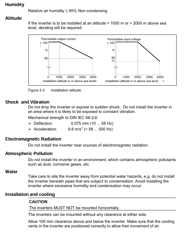
Humidity: ≤ 95% (no condensation);
Altitude: ≤ 1000m without capacity reduction, over 1000m requires capacity reduction (e.g. output current drops to 80% at 2000m);
Protection: Avoid vibration (in accordance with DIN IEC 68-2-6, acceleration ≤ 9.8m/s ²), electromagnetic radiation, dust/corrosive gases, and water hazards.
2. Mechanical installation
Installation method: Only vertical installation is allowed, A frame (low power) can adapt to 35mm standard guide rail (EN 50022), B/C frame requires bolt fixation.
Spacing and dimensions:
Frame dimensions Overall dimensions (width x height x depth) mm Tightening method Tightening torque Installation gap
A 73 × 173 × 149 2 M4 bolts/nuts+washers 2.5Nm (with washers), 100mm up and down, with no gap on both sides
B 149 × 202 × 172 4 M4 bolts/nuts+washers 2.5Nm (with washers), 100mm up and down, with no gap on both sides
C 185 × 245 × 195 4 M5 bolts/nuts+washers 2.5Nm (with washers), 100mm up and down, with no gap on both sides
3. Electrical installation (core safety requirements)
Grounding: It must be grounded according to the IEC 536 Class 1 standard, and the PE wire section should not be smaller than the power wire to avoid the risk of electric shock; The reference voltage for motor grounding should be consistent with the ground voltage.
Power and motor wiring:
Input terminals: single-phase (L/L1, N/L2), three-phase (L1, L2, L3); Motor terminals (U, V, W), DC terminals (DC+, DC -);
Power outage requirement: Wait for 5 minutes after power outage before opening the cover (discharge of DC bus capacitor). The terminal may still carry dangerous voltage after power outage.
Special scenario configuration:
Scene configuration requirements
IT power supply (ungrounded): Remove the internal "Y" capacitor (see Appendix D/E) and install the output reactor; When the output is grounded, the frequency converter trips (F0001)
The use of RCD requires the selection of B-type RCD, with a trip limit of 300mA, neutral grounding, and only one frequency converter for a single RCD. The motor cable should be ≤ 50m (shielded)/100m (unshielded)
Long cable motor cable ≤ 50m (shielded)/100m (unshielded), special configuration required for over distance
EMI protection: Power cables (power+motor) and control cables are wired separately (in different cable trays/conduits), motor cables are shielded/armored and grounded at both ends, and contactor coils require R-C suppressors (AC) or freewheeling diodes (DC).
Debugging process and operation
1. Operation panel selection and configuration
SDP (Status Display Panel): default configuration, 2 LEDs (green/yellow) display operating status (such as "green+yellow constant light=ready" and "red light flashing for 0.3s=overcurrent"), compatible with motor rated parameters (power, voltage, current, frequency), default control: analog potentiometer frequency modulation rate (0-10V corresponds to 0-50/60Hz), ramp time 10s.
BOP (Basic Operation Panel): Optional accessory, 5-digit 7-segment display, requires parameter activation:
Enable control: set P0700=1 (instruction source is BOP), P1000=1 (frequency given as BOP);
Core button functions:
Key Function Remarks
The start button is disabled by default for starting the motor, and P0700=1 is required to enable it
Press and hold the stop button OFF1 (slope stop)/OFF2 (free stop) twice or once to keep it enabled
When the reverse button switches the motor direction to reverse, it displays a "-" or flashes a decimal point
Fn key to view additional information (DC bus voltage, output current, etc.) Short press to jump to r0000, long press to cycle display status
AOP (Advanced Operating Panel): Optional accessories, supporting multiple languages, parameter upload/download, and multi machine (30 units) control. Please refer to the AOP independent manual.
2. Quick debugging (key process)
Enter debugging mode: set P0010=1 (fast debugging filtering);
Basic configuration:
P0700: Select instruction source (e.g. 1=BOP, 2=numeric input);
P1000: Select frequency given (e.g. 1=BOP, 2=analog input);
P0100: Select region (0=Europe 50Hz/kW, 1=North America 60Hz/hp);
Motor parameter settings (matching motor nameplate):
P0304: Rated voltage of motor (V);
P0305: Rated current of motor (A);
P0307: Rated power of motor (kW/hp, determined by P0100);
P0310: Rated frequency of motor (Hz);
P0311: Rated speed of motor (rpm);
End debugging: Set P3900=2 (perform motor calculation+restore P0010=0), and it can be run after completion.
3. Factory reset
Operation: Set P0010=30 (reset filter) → P0970=1 (trigger reset), the reset process takes about 3 minutes, and the parameters will return to factory default after reset.
4、 Detailed Explanation of Parameter System
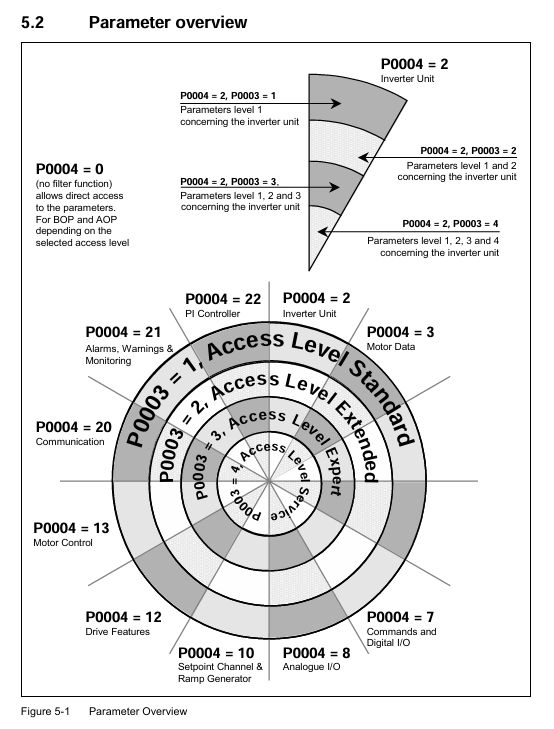
1. Parameter access control
Access level (P0003): Level 4 permission, determining the visible parameter range:
1 (Standard): Basic operating parameters;
2 (Extension): Add motor and control related parameters;
3 (Expert): Add advanced debugging parameters;
4 (Service): Hidden parameters (requires P3950=1 to unlock).
Parameter filtering (P0004): grouped by function for quick search:
P0004 value function grouping includes parameter examples
2 frequency converter units r0026 (DC bus voltage), P1800 (switching frequency)
Motor data P0304 (rated voltage), P0610 (motor I ² t protection)
7 Instructions and Digital I/O P0700 (Command Source), P0731 (Digital Output)
10 Frequency Given and Slope P1000 (Frequency Given), P1120 (Slope Rise Time)
2. Classification of core parameters
Parameter Category Key Parameter Function Description Default Values (Europe)
Debugging Control P0010 Debugging Mode Filter 0 (Normal)
P3900 ends debugging 0 (without performing motor calculations)
P0970 Factory reset 0 (not triggered)
Motor protection P0610 motor I ² t protection 2 (enabled)
P0335 motor cooling method 0 (self cooling)
Operation control P1300 control mode 1 (linear V/f with FCC)
P1120 Slope Rise Time 10s
P1121 Slope descent time 10s
Troubleshooting and Warning
1. Fault indication method
SDP: Fault is determined by the combination of on/off/flashing of two LEDs (such as "dual lights flashing together=ROM fault" and "dual lights flashing alternately=RAM fault"), as shown in Table 6-1.
BOP/AOP: Display fault codes (Fxxx) or alarm codes (Axxx), and view historical faults (P0947 stores the last 8 faults).
2. Common faults and solutions
Fault code, fault type, possible causes, and solutions
F0001 grounding fault 1. The motor power does not match the frequency converter; 2. Motor/cable grounding; 3. Motor overload: 1. Check the power between P0307 and the frequency converter; 2. Check the insulation of motor windings/cables; 3. Reduce load
F0002 DC bus overvoltage 1. Input voltage too high; 2. The slope descent time is too short; 3. The regenerative energy of the load is high. 1. Check the power supply voltage (which should be between 200-480V ± 10%); 2. Increase P1121 (slope descent time); 3. Install a braking unit
F0051 parameter EEPROM fault EEPROM read/write failure 1. Perform factory reset (P0010=30+P0970=1); 2. Replace the frequency converter (if reset is ineffective)
3. Fault reset method
Power off and restart the frequency converter;
Press the reset button on BOP/AOP;
Triggered by digital input 3 (default function is fault reset).
Technical specifications and certification
1. Core electrical specifications
Project specification parameters
Input voltage: 1 phase 200-240V ± 10%, 3 phases 200-240V ± 10%, 3 phases 380-480V ± 10%
Input frequency 47-63Hz
Output frequency 0-650Hz
Overload capacity 50% overload (60s/5min, based on rated output current)
Efficiency 96-97%
Control mode linear V/f (P1300=0), linear V/f with FCC (P1300=1), secondary V/f (P1300=2), multi-point V/f (P1300=3)
Interface: 3 digital inputs, 1 analog input (0-10V), 1 relay output, 1 analog output (0-20mA), RS485 communication
2. Certification and Compliance
Protection level: IP20;
Certification standards: UL, cUL, CE, C-tick;
Directive Compliance: Compliant with EMC Directive 89/336/EEC and Low Voltage Directive 73/23/EEC;
EMC classification: Supports Class 1 (industrial general), Class 2 (filtering industry), Class 3 (civil/commercial/light industry, requiring Class B filters).
Optional accessories
Accessory type, specific product function
Equipment independent accessory BOP (basic operation panel) basic parameter setting and operation control
AOP (Advanced Operating Panel) with multiple languages, parameter upload/download, and multi machine control
PROFIBUS module realizes PROFIBUS communication
PC Connection Kit PC and Inverter/AOP Connection
DriveMonitor/STARTER PC Debugging Tool
The equipment relies on accessories such as EMC filters (Class A/B) to reduce electromagnetic radiation and comply with different EMC levels
Input/output reactors suppress harmonics and protect frequency converters (necessary for IT power supply)
The wiring board facilitates cable connection and shielding
Safety Warning (Core Emphasis)
Personnel qualifications: Only "qualified personnel" are allowed to operate (training is required for circuit switching, use of protective equipment, and first aid skills);
Voltage risk: Do not open the cover (capacitor discharge) within 5 minutes after power failure, and dangerous voltage may still be present after input/motor/DC terminals are powered off;
Prohibition of substitution: cannot be used as an "emergency stop device" (requires separate configuration of emergency stop devices that comply with EN 60204);
Motor protection: The motor parameters (P0304/P0305, etc.) must be accurately configured, otherwise the motor overload protection will fail
- YOKOGAWA
- Reliance
- ADVANCED
- SEW
- ProSoft
- WATLOW
- Kongsberg
- FANUC
- VSD
- DCS
- PLC
- man-machine
- Covid-19
- Energy and Gender
- Energy Access
- Renewable Integration
- Energy Subsidies
- Energy and Water
- Net zero emission
- Energy Security
- Critical Minerals
- A-B
- petroleum
- Mine scale
- Sewage treatment
- cement
- architecture
- Industrial information
- New energy
- Automobile market
- electricity
- Construction site
- HIMA
- ABB
- Rockwell
- Schneider Modicon
- Siemens
- xYCOM
- Yaskawa
- Woodward
- BOSCH Rexroth
- MOOG
- General Electric
- American NI
- Rolls-Royce
- CTI
- Honeywell
- EMERSON
- MAN
- GE
- TRICONEX
- Control Wave
- ALSTOM
- AMAT
- STUDER
- KONGSBERG
- MOTOROLA
- DANAHER MOTION
- Bentley
- Galil
- EATON
- MOLEX
- Triconex
- DEIF
- B&W
- ZYGO
- Aerotech
- DANFOSS
- KOLLMORGEN
- Beijer
- Endress+Hauser
- schneider
- Foxboro
- KB
- REXROTH
- YAMAHA
- Johnson
- Westinghouse
- WAGO
- TOSHIBA
- TEKTRONIX
- BENDER
- BMCM
- SMC
- HITACHI
- HIRSCHMANN
- XP POWER
- Baldor
- Meggitt
- SHINKAWA
- Other Brands
- UniOP
- KUKA
- IBA
- Beckhoff
-
LTI SC52.0040.0012.0000.0 - Servo Drive
-
Lti SC52.0040.0012.0000.0 - Servo Drive
-
Milton Industries LTI Tool By Milton LT1240 - 1/2" Drive Lugnut Remover
-
LTi Drives SO84.200.P030.0000.0-W - Servo Spindle Drive
-
LTI DRIVES LSP08-035-320-30-B0R1PY170 - Servo Motor
-
LTI DRIVES SE84.200.SC00.0001.0-W - Servo Drive
-
Lust CDE34.005.W2.2 - Lti Drives Controller
-
LTi SO84.012.0030.0011.2 - ServoOne Servo Drive
-
LTi Drives SO CM-P.0010.11.00.0 - Servo Drive Controller
-
LTi CDE34.017.W3.0 - Servo Drive
-
LTI Drives CDB32.004, C2.0,SH - Positioning Controller
-
LUST CM-CAN1 - LTi DRIVES Communication Module
-
LTi SO84.012.1030.0000.2 - Servo Drive
-
LTI MOOG CDE54.044 - PITCHMASTER FREQUENCY CONVERTER 181-01019
-
MOOG LTI 181-01019 CDE54.044 - PITCHMASTER FREQUENCY CONVERTER
-
Lust LTi Drives CDE34.010,D2.0 - Servo Drive Controller
-
LTI SO84.032.0003.0101.2 - Servo Drive
-
Seagate 9CC132-302 Harris LTI-CS IRT-34-0021-01 - Hard Drive 160GB
-
LTI SO84.032.0003.0001.2 - Servo Drive
-
LTI SO24.007.0070.0000.1 - SERVO CONTROLLER
-
LTi drive CDA32.003.C3.0.H05-01.PC1 - Servo Drive
-
LTI SO84.016.0030.0000.2 - SERVO CONTROLLER
-
LUST LTI CD A34.008,W1.4, BR - SERVO DRIVE
-
MOOG LTI 181-01019 CDE54.044 - PITCHMASTER FREQUENCY CONVERTER
-
LTI MOOG 181-01019 - PITCH Master Servo Drive CDE54.044
-
LTI SERVO ONE SO84.045.0030.0001.2-W - Drive
-
LUST LTi SO84.032.0040.0000.2 - SERVO ONE DRIVE
-
LTi Drives LSH-074-2-30-3 20/T1,G6.1M - SERVO MOTOR
-
LTI SO84.016.0000.0101.2 - servo drive
-
LTI SA54.0550.0033.0000.0 - Servo Drive
-
LTI SA54.0550.0033.0000.0 - Servo Drive
-
LTI LT 4850 - 3/8" Drive 3-Pc Twist Socket Transmission Drain Plug Removal System
-
LTI Tools LT4400-30 Lock Technology - 3/4" Twist Socket 1/2" Drive Lugnut Remover
-
LTI Tools LT-1400C - 1/2 Drive Wheel Torque Extension Tool
-
LTI Tools LT1250 - 1/2" Drive Dual Sided Socket Lug Nut Remover Tool
-
LTI SO84.032.0003.0101.2 - Servo Drive
-
LTI MOOG 181-01019 - PITCH Master Servo Drive CDE54.044
-
MOOG LTI 181-01019 CDE54.044 - PITCHMASTER FREQUENCY CONVERTER
-
MOOG LTI 181-01019 CDE54.044 - PITCHMASTER FREQUENCY CONVERTER
-
MOOG LTI 181-01019 CDE54.044 - PITCHMASTER FREQUENCY CONVERTER
-
LTI SA54.0550.0033.0000.0 - Servo Drive
-
LTI Tools LT-4800 - 7 Piece Twist Socket 3/8" Drive Oil Drain Plug Removal Set
-
LTI SA54.0550.0033.0000.0 - Servo Drive
-
LTI Drive SO24.007.00300000.0 - Servo Drive
-
LTI TOOLS LTI 1400-I - Drive Wheel Torque Extension
-
LTI Tools LT4400-3 - 3/4" 19mm Twist Socket 1/2" Drive Lugnut
-
LTI TOOLS LTI 1400-BB - Drive Wheel Torque Extension
-
LTI SO84.032.0003.0101.2 - Servo Drive
-
LTI Tools LT-4512 - 3/8" Drive 12mm Twist Socket
-
LTI MOTION Luster SO84.032.0003.0001.2 - Servo Drive
-
LTI Tool By Milton LT1600P - 1" Drive Torx Stick
-
LTI Lust VF1424L,HF,OP2,S56 - Variable Frequency Drive
-
LUST CDA32.004,C1.4,H08,B0 - SERVO DFRIVE CM-CAN1 Module
-
LTI SO84.045.0002.0001.2-W - Drive
-
LTI Lust VF1404M,C9,PT1,BR1 - Inverter Type VF1404M
-
LTI SA54.0550.0033.0000.0 - Servo Drive
-
LTI Tools LT-1400C - 1/2" Drive Wheel Torque Extension
-
Lust LTI DRiVES CDA32.006, C3.0, H09 - Variateur De Fr茅quence Frequency Inverter
-
LTI MOOG CDE54.044 - PITCH master SERVO DRIVE
-
LTI MOOG CDE54.044 - PITCH master SERVO DRIVE
-
LTI SO84.143.0020.0101.2-W - servo drive
-
LTI MOTION SC34.0200.0011.0000.0 - Servo drives
-
LTI SO84.032.0003.0001.2 - Servo Drive
-
LTI DRIVES GmbH MS100 - Assembly Set Mounting Kit
-
LTI SO84.032.0003.0001.2 - Servo Drive
-
LTI SO84.032.0003.0001.2 - Servo Drive
-
LTI MOTION SO84.032.0003.0101.2 - servo drive
-
LTI SO84.032.0003.0101.2 - Servo Drive
-
LTI MOOG CDE54.044 - PITCH master SERVO DRIVE
-
LTI MOTION CDE32.004.C2.4 - Servo drives
-
LTI CDD34.032锛學x.x锛孊R锛孭C1 - Servo Drive
-
Lust LTI DRiVES CDA32.006, C3.0, H09 - Inversor De Frecuencia Frequency Inverter
-
Lust SO84.008.0030.1000.0 - Servo One LTi Drive
-
LTI MOTION SO84.032.0003.0101.2 - Servo drives
-
LUST LTi CDA32.004,C1.4 - SERVO DRIVE
-
LTI MOOG CDE54.044 - PITCH Master SERVO DRIVE
-
LTI KEBA CDB32.004 C2.7, SH - PN: 08673530 Frequency Inverter
-
LTI Tools LT-1400C - 1/2" Drive Wheel Torque Extension
-
LTI LT1400-E - 1/2" Drive Wheel Torque Extension
-
LTI MOOG 181-01019 - PITCH master SERVO DRIVE CDE54.044
-
LTI LSN-097-0510-30-560/T1 - Actuator Motor
-
LTI Tools LT 4800 - 7 Piece 3/8" Drive Twist Socket Oil Drain Plug Removal System
-
LTI DRIVES GmbH MS100 - MONTAGESET Assembly Set Mounting Kit
-
Lti SC52.0040.0012.0000.0 - Servo Drive
-
LTI DRIVES GmbH MS100 - Juego De Montaje Assembly Set Mounting Kit
-
LTi DSM4-14.2-21R83-200 - Drives servomoteur Servo Motor
-
MOOG CDE 54.044.GDA - Pitch Master Industrielle Turbine Lti Drive
-
LTI SO24.004.0030.1000.0 - Servo Drive Controller
-
Lti MOOG CDE54.044 - Pitch Master Servo Drive
-
Lust LTI DRiVES CDA32.006, C3.0, H09 - Inverter
-
LTI MOTION GMBH CDB34.006,W3.0,PC1,H39 - Frequency inverter
-
LTI SO84.032.0003.0001.2 - Servo Drive
-
MOOG CDE 54.044.D - Pitch Master Industrielle Turbine Lti Drive
-
LTI TOOLS LT-1460 - 1/2" DRIVE WHEEL TORQUE EXTENSION KIT 5 PIECE SET
-
Lust Cdb32.003, C2.4 - Lti Drives Servoregulador Frecuencia Servo Controller Inverter
-
Lust LTI DRIVES CDA32.006, C3.0, H09 - Frequency Inverter
-
Lust Lti SO82.004.0030.0000.2 - Servo Drive
-
LTI MOTION SC34.0200.0011.0000.0-SL - Servo drives
-
LTI MOTION SA54.0075.0033.0000.0 - Servo drives
-
LTI MOTION SC32.0075.1011.0000.0 - Servo drives
-
Lust Cdb32.003, C2.4 - Lti Drives Servo Controller Frequency Inverter
-
LTI MOOG CDE54.044 - PITCH master SERVO DRIVE
-
Lust Lti Cde34.006,W2.0,Br - Servo Drive
-
Lust LTi MOTION CDE34.044,W2.4,H13 - Servo Drive
-
Lust LTi Drives Cde32.008, W2.2.br - Positionierregler Posici贸n Mando Positioning Controller
-
LTI MOOG CDE54.044 - PITCH master SERVO DRIVE
-
LUST Antriebstechnik B-DS 125.1 - LTi DRiVES Accessories Drive Component
-
LTi LSMM13-100-4N-001 - servo motor
-
Lti CDA32.004 C1.4, H08, B0 - PN: 3084456 Frequency Inverter
-
LTI MOTION CDE34.006.WXX.PC1 - Servo drives
-
LTI MOTION SO24.007.0030.1000.0 - Servo drives
-
Lust CDD34.005.C2.1 - LTI Drive
-
Lti SC52.0040.0012.0000.0 - Servo Drive
-
LTI Tools LT4400-30 - 1/2" Drive 19mm 3/4" Twist Socket
-
Lust LTi Drives Cde32.008, W2.2.br - Positionierregler Posici贸n Mando Positioning Controller
-
LTI MOOG CDE54.044 - PITCH master SERVO DRIVE
-
LUST Antriebstechnik B-DS 125.1 - LTi DRiVES Accessories Drive Component
-
LTI DRIVES GmbH MS100 - MONTAGESET Assembly Set Mounting Kit
-
Lust LTi SO84.032.0043.0000.2 - Servo one Drive
-
LUST LTi Drives CM-CAN1 - Modulo Di Comunicazione Communication Module
-
LTI drive CDF 30.008.C3.6 - Servo Drive
-
LTI MOOG 181-01019 - PITCH master SERVO DRIVE
-
LTI CDB34.014,W2.4,BR,SH - Servo Driver
-
Lti SC52.0040.0012.0000.0 - Servo Drive
-
LTi Drive CDF30.002 - Power Supply Fuse
-
LTI Tools LT-4621-D - Deep Well Twist Socket 3/8" Drive 1/2"
-
LTI MOOG PITCH master CDE54.044 - SERVO DRIVE Frequency Converter
-
LTI SO84.076.S030.0001.2-W - Servo One Drive

K-JIANG

Add: Jimei North Road, Jimei District, Xiamen, Fujian, China
Tell:+86-15305925923