
K-WANG


SIEMENS SITRANS P DS III series pressure transmitter
Measurement type:
Basic measurements: Gauge Pressure, Absolute Pressure, Differential Pressure;
Extended measurement: Through parameter configuration and additional components such as flow orifice plates and remote seals, liquid level, volume, mass, volumetric flow, and mass flow measurements can be achieved.
SIEMENS SITRANS P DS III series pressure transmitter
Product positioning and core functions
Product model: Covering three sub series: 7MF4.33., 7MF4.34., and 7MF4.35., suitable for pressure measurement of corrosive, non corrosive, and hazardous gases, vapors, and liquids.
Measurement type:
Basic measurements: Gauge Pressure, Absolute Pressure, Differential Pressure;
Extended measurement: Through parameter configuration and additional components such as flow orifice plates and remote seals, liquid level, volume, mass, volumetric flow, and mass flow measurements can be achieved.
Core output: Always a 4-20mA load independent DC signal, supporting three communication protocols: HART, PROFIBUS PA, and Foundation Fieldbus.
Explosion proof features: Provides two explosion-proof versions: intrinsic safety (Ex i) and explosion-proof (Ex d), compliant with ATEX 94/9/EC directive, can be installed in hazardous environments in zones 0/1/2, and has an EC type inspection certificate.
Safety warning system (core emphasis)
1. Risk grading standards
The document adopts a four level risk warning system, clarifying the definitions and response requirements for different risk levels:
Warning level identification, risk description, typical scenarios
DANGER red safety warning symbol. Failure to take measures may result in death or serious personal injury. Failure to ventilate during toxic medium leakage
Warning red safety warning symbol. Failure to take measures may result in death or serious personal injury. Use of non explosion proof equipment in hazardous areas
CAUTION yellow safety warning symbol. Failure to take measures may result in minor personal injury from contact with equipment surfaces above 70 ℃
NOTICE unsigned failure to take measures may result in property damage and unauthorized modification of equipment
2. Key safety requirements
Personnel qualifications: Only "qualified personnel" are allowed to operate, and the following abilities are required:
Master the knowledge of safety protection for electrical circuits, high-voltage equipment, and hazardous media;
Familiar with electrical operation standards in hazardous areas;
Able to use protective equipment and possess first aid skills.
Special requirements for hazardous areas:
Explosion proof type selection: The appropriate explosion-proof version (Ex i/Ex d/nA) should be selected based on the hazardous area level (such as Zone 0, Zone 1, Zone 2), and non corresponding explosion-proof components should be prohibited;
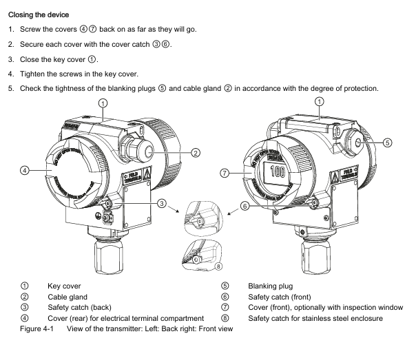
Electrostatic protection: When operating in hazardous areas, close the key cover and tighten the screws to avoid static electricity accumulation and explosion;
Wiring specifications: Use B-type RCD (trip limit 300mA), the power supply must comply with SELV (safety isolation ultra-low voltage) requirements, and shielded cables must only be grounded at one end.
Equipment modification restrictions: Only modifications according to document instructions are allowed. Unauthorized modifications will result in the invalidation of warranty and the invalidation of explosion-proof certification.
Installation specifications (mechanical+electrical)
1. Preparation before installation
Arrival inspection:
Check the packaging and equipment for any transportation damage. If there is any damage, immediately claim compensation from the shipping company and keep the damaged parts;
Compare the order with the shipping documents to confirm the integrity and correctness of the equipment model and accessories (such as flanges and seals);
Prohibit the use of damaged or incomplete equipment (especially in hazardous areas, which may cause explosions).
Environmental conditions: The following environmental requirements must be met, otherwise it may affect equipment performance or cause safety accidents:
Remarks on Environmental Parameter Requirements
Operating temperature -40~85 ℃ (Ex i/T6 version -40~60 ℃) Avoid direct sunlight, and additional heat dissipation is required in high-temperature environments
Storage temperature -50~85 ℃. The packaging only provides limited moisture-proof protection and requires additional protection
Humidity ≤ 95% (no condensation). Moisture proof devices need to be installed in condensing environments
Vibration acceleration ≤ 9.8m/s ² (in accordance with DIN IEC 68-2-6) Keep away from strong vibration equipment (such as pumps and compressors)
The output current drops to 80% when the altitude is ≤ 2000m (over altitude requires reduced capacity)
2. Mechanical installation specifications
General requirements:
Installation method: Only vertical installation is allowed to avoid shell rotation (which may damage the measuring unit);
Explosion proof gap: The distance between the explosion-proof surface of explosion-proof equipment and fixed components should be ≥ 40mm to prevent explosions caused by high-temperature gas leakage;
Sealing selection: The flange seal should be compatible with the process medium (such as PTFE seal used in FDA compliant scenarios), and the seal should be centered without obstructing the movement of the diaphragm.
Scenario based installation differences: According to the measurement medium state, the equipment installation position and pipeline layout need to be designed differently:
Measurement medium installation position pipeline requirements
The gas transmitter is higher than the pressure tapping point and the pipeline is inclined towards the pressure tapping point, which facilitates the discharge of condensed water
The liquid/steam transmitter is located below the pressure tapping point and the pipeline is inclined towards the pressure tapping point for easy gas discharge (a condensation tank needs to be installed for steam)
The flange of the liquid level (open container) is lower than the minimum measured liquid level, and the negative pressure chamber is open to the atmosphere. The open interface needs to be protected to prevent pollution
The flange of the liquid level (closed container) is lower than the minimum measured liquid level, and in strong condensation scenarios, negative pressure pipelines need to be filled and condensation tanks need to be installed
3. Electrical installation specifications
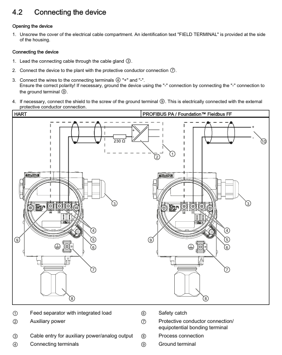
Grounding requirements:
Grounding must be carried out according to IEC 536 Class 1 standard, and the cross-sectional area of the PE wire must not be smaller than that of the power wire;
Explosion proof equipment requires equipotential connection (excluding Ex i type) to avoid explosion caused by compensating current;
Grounding through the "+" terminal is prohibited, and grounding through the "-" terminal is required (otherwise it may damage the equipment).
Wiring specifications:
Cable selection: High temperature environments (≥ 60 ℃) require the use of cables with a temperature resistance of ≥ 80 ℃, and shielded cables must meet EMC requirements;
Cable gland: Only use gland compatible with explosion-proof type, and the tightening torque must comply with technical specifications (such as M20 gland torque of 2.5Nm);
Cable separation: Power cables (power+motor) and control cables need to be wired separately (in different cable trays/conduits) to avoid EMI interference.
Special wiring in hazardous areas:
IT power supply system: It is necessary to remove the internal "Y" capacitor of the equipment and install an output reactor;
Conduit system: A spark barrier should be installed at a designated distance from the equipment input port, in compliance with national regulations and explosion-proof certification requirements.
Debugging process (scenario based steps)
1. Preparation before debugging
Power on preheating: After the equipment is powered on, it needs to be preheated for 5 minutes to ensure stable measurement values;
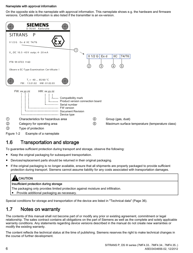
Parameter verification: Confirm that the equipment nameplate parameters (such as range, power supply, explosion-proof level) are consistent with the actual operating requirements;
Tool preparation: Select the appropriate tool (HART communicator, SIMATIC PDM, BOP/AOP panel) based on the communication protocol.
2. Scenario based debugging steps
(1) Gas medium debugging
Close all valves and apply range starting pressure (such as 0mbar) to the transmitter through the testing interface;
Check if the output signal is 4mA, and calibrate if there is a deviation;
Close the test valve, open the pressure tap valve, and then slowly open the process valve;
Adjust to the end pressure of the range, confirm that the output signal is 20mA, and complete the debugging.
(2) Liquid medium debugging
Close all valves, open the pressure tap valve and balance valve;
If the transmitter is located below the differential pressure sensor, open the drain valve to release air (until no bubbles of liquid flow out); If it is above, open the exhaust valve to release air;
Close the drain/exhaust valve, open the positive pressure side differential pressure valve and exhaust valve (close after emptying the bubbles);
Repeat step 3 on the negative pressure side and close the differential pressure valve;
Open the positive pressure side differential pressure valve 1/2 turn and calibrate the zero point (0 bar corresponds to 4mA);
Close the balance valve, fully open the differential pressure valve, and complete the debugging.
(3) Steam medium debugging
Close all valves, open the pressure tapping valve and balance valve, and wait for the differential pressure pipeline and the steam in the condensing tank to completely condense;
Open the differential pressure valve and exhaust valve on the positive pressure side (close after draining the condensate until there are no bubbles);
Repeat step 2 on the negative pressure side and close the differential pressure valve;
Open the positive pressure side differential pressure valve 1/2 turn and calibrate the zero point (0 bar corresponds to 4mA);
Close the balance valve and fully open the differential pressure valve;
Temporarily open the drain valve to clean the pipeline (close before steam leakage) and complete the debugging.
Maintenance and troubleshooting
1. Regular maintenance
Maintenance cycle: The cycle should be defined based on the corrosiveness of the medium and the concentration of environmental dust (such as once every 3 months for strong corrosion scenarios and once every 6 months for cleaning scenarios).
Core maintenance project:
Precautions for maintaining project steps
Sealing inspection 1. Clean the shell and seal; 2. Check for cracks/damage; 3. Lubrication or replacement of differential pressure equipment seals requires Siemens authorized personnel to operate
Anti static tools should be used in hazardous areas where the dust layer on the surface of the dust cleaning and removal equipment is greater than 5mm to avoid the accumulation of static electricity
Use a soft brush and an appropriate solvent to clean film deposits. Do not use sharp tools to avoid scratching the film
Parameter calibration: Regularly verify the range and zero point (e.g. every 6 months) using a standard pressure source and record calibration data
2. Fault handling
Fault indication method:
SDP panel: indicates faults through a combination of on/off/flashing of 2 LEDs (such as alternating flashing of dual lights=RAM fault);
BOP/AOP panel: displays Fxxx fault codes (such as F0001=ground fault) or Axxx alarm codes (such as A0002=over range alarm);
HART/PA/FF: View detailed fault information (such as sensor disconnection, EEPROM failure) through communication tools.
Common troubleshooting solutions:
Fault code, fault type, possible causes, and solutions
F0001 grounding fault 1. Motor power does not match equipment; 2. Cable grounding; 3. Equipment overload: 1. Check P0307 (motor power); 2. Check the insulation of the cable; 3. Reduce load
F0002 DC bus overvoltage 1. Input voltage exceeds the range; 2. The slope descent time is too short; 3. The regenerative energy of the load is high. 1. Check the power supply voltage (which should be between 10.5-45V DC); 2. Increase P1121 (slope descent time); 3. Install a braking unit
F0051 EEPROM fault EEPROM read/write failure 1. Perform factory reset (P0010=30+P0970=1); 2. Replace the electronic unit (if reset is ineffective)
Fault reset method:
Power off and restart the device;
Press the reset button on the BOP/AOP panel;
Trigger reset through digital input 3 (parameters need to be configured in advance).
Technical specifications (core parameters)
1. Pressure range (HART/PA/FF universal)
Measurement Type Range Maximum Operating Pressure (MAWP) Maximum Test Pressure
Gauge pressure 0.01~700bar g 0.04~800bar g 0.06~800bar g
Absolute pressure 8.3mbar~100bar a 1.5~160bar a 6~250bar a
Differential pressure 1mbar~30bar 32~420bar 32~600bar
2. Temperature range
Temperature Type Range Remarks
The ambient temperature is -40~85 ℃ for Ex i/T6 version and -40~60 ℃ for Ex d/T4 version
Process temperature -40~250 ℃ can reach 250 ℃ with cooling extension, and -40~100 ℃ without extension
Storage temperature -50~85 ℃, limited moisture-proof packaging, requires additional protection
3. Electrical and communication parameters
Parameters: HART PROFIBUS PA/Foundation Fieldbus
Supply voltage DC 10.5~45V (Ex i type 10.5~30V) Bus supply DC 9~32V (Ex i type 9~24V)
Current consumption - maximum 15.5mA (in case of fault)
Output signal 4-20mA (load independent) digital signal (compliant with PROFIBUS PA/FF specifications)
EMC compatibility complies with EN 61326, NAMUR NE 21 complies with EN 61326, NAMUR NE 21
4. Certification and Protection
Protection level: IP65/IP68 (EN 60529), NEMA 4X;
Explosion proof certification: ATEX(PTB 99 ATEX 1160)、FM(Certificate of Compliance 3008490)、CSA(Certificate of Compliance 1153651);
Compliance directives: EMC 2004/108/EC, ATEX 94/9/EC, PED 97/23/EC.
- YOKOGAWA
- Reliance
- ADVANCED
- SEW
- ProSoft
- WATLOW
- Kongsberg
- FANUC
- VSD
- DCS
- PLC
- man-machine
- Covid-19
- Energy and Gender
- Energy Access
- Renewable Integration
- Energy Subsidies
- Energy and Water
- Net zero emission
- Energy Security
- Critical Minerals
- A-B
- petroleum
- Mine scale
- Sewage treatment
- cement
- architecture
- Industrial information
- New energy
- Automobile market
- electricity
- Construction site
- HIMA
- ABB
- Rockwell
- Schneider Modicon
- Siemens
- xYCOM
- Yaskawa
- Woodward
- BOSCH Rexroth
- MOOG
- General Electric
- American NI
- Rolls-Royce
- CTI
- Honeywell
- EMERSON
- MAN
- GE
- TRICONEX
- Control Wave
- ALSTOM
- AMAT
- STUDER
- KONGSBERG
- MOTOROLA
- DANAHER MOTION
- Bentley
- Galil
- EATON
- MOLEX
- Triconex
- DEIF
- B&W
- ZYGO
- Aerotech
- DANFOSS
- KOLLMORGEN
- Beijer
- Endress+Hauser
- schneider
- Foxboro
- KB
- REXROTH
- YAMAHA
- Johnson
- Westinghouse
- WAGO
- TOSHIBA
- TEKTRONIX
- BENDER
- BMCM
- SMC
- HITACHI
- HIRSCHMANN
- XP POWER
- Baldor
- Meggitt
- SHINKAWA
- Other Brands
- UniOP
- KUKA
- IBA
- Beckhoff
-
LTI SC52.0040.0012.0000.0 - Servo Drive
-
Lti SC52.0040.0012.0000.0 - Servo Drive
-
Milton Industries LTI Tool By Milton LT1240 - 1/2" Drive Lugnut Remover
-
LTi Drives SO84.200.P030.0000.0-W - Servo Spindle Drive
-
LTI DRIVES LSP08-035-320-30-B0R1PY170 - Servo Motor
-
LTI DRIVES SE84.200.SC00.0001.0-W - Servo Drive
-
Lust CDE34.005.W2.2 - Lti Drives Controller
-
LTi SO84.012.0030.0011.2 - ServoOne Servo Drive
-
LTi Drives SO CM-P.0010.11.00.0 - Servo Drive Controller
-
LTi CDE34.017.W3.0 - Servo Drive
-
LTI Drives CDB32.004, C2.0,SH - Positioning Controller
-
LUST CM-CAN1 - LTi DRIVES Communication Module
-
LTi SO84.012.1030.0000.2 - Servo Drive
-
LTI MOOG CDE54.044 - PITCHMASTER FREQUENCY CONVERTER 181-01019
-
MOOG LTI 181-01019 CDE54.044 - PITCHMASTER FREQUENCY CONVERTER
-
Lust LTi Drives CDE34.010,D2.0 - Servo Drive Controller
-
LTI SO84.032.0003.0101.2 - Servo Drive
-
Seagate 9CC132-302 Harris LTI-CS IRT-34-0021-01 - Hard Drive 160GB
-
LTI SO84.032.0003.0001.2 - Servo Drive
-
LTI SO24.007.0070.0000.1 - SERVO CONTROLLER
-
LTi drive CDA32.003.C3.0.H05-01.PC1 - Servo Drive
-
LTI SO84.016.0030.0000.2 - SERVO CONTROLLER
-
LUST LTI CD A34.008,W1.4, BR - SERVO DRIVE
-
MOOG LTI 181-01019 CDE54.044 - PITCHMASTER FREQUENCY CONVERTER
-
LTI MOOG 181-01019 - PITCH Master Servo Drive CDE54.044
-
LTI SERVO ONE SO84.045.0030.0001.2-W - Drive
-
LUST LTi SO84.032.0040.0000.2 - SERVO ONE DRIVE
-
LTi Drives LSH-074-2-30-3 20/T1,G6.1M - SERVO MOTOR
-
LTI SO84.016.0000.0101.2 - servo drive
-
LTI SA54.0550.0033.0000.0 - Servo Drive
-
LTI SA54.0550.0033.0000.0 - Servo Drive
-
LTI LT 4850 - 3/8" Drive 3-Pc Twist Socket Transmission Drain Plug Removal System
-
LTI Tools LT4400-30 Lock Technology - 3/4" Twist Socket 1/2" Drive Lugnut Remover
-
LTI Tools LT-1400C - 1/2 Drive Wheel Torque Extension Tool
-
LTI Tools LT1250 - 1/2" Drive Dual Sided Socket Lug Nut Remover Tool
-
LTI SO84.032.0003.0101.2 - Servo Drive
-
LTI MOOG 181-01019 - PITCH Master Servo Drive CDE54.044
-
MOOG LTI 181-01019 CDE54.044 - PITCHMASTER FREQUENCY CONVERTER
-
MOOG LTI 181-01019 CDE54.044 - PITCHMASTER FREQUENCY CONVERTER
-
MOOG LTI 181-01019 CDE54.044 - PITCHMASTER FREQUENCY CONVERTER
-
LTI SA54.0550.0033.0000.0 - Servo Drive
-
LTI Tools LT-4800 - 7 Piece Twist Socket 3/8" Drive Oil Drain Plug Removal Set
-
LTI SA54.0550.0033.0000.0 - Servo Drive
-
LTI Drive SO24.007.00300000.0 - Servo Drive
-
LTI TOOLS LTI 1400-I - Drive Wheel Torque Extension
-
LTI Tools LT4400-3 - 3/4" 19mm Twist Socket 1/2" Drive Lugnut
-
LTI TOOLS LTI 1400-BB - Drive Wheel Torque Extension
-
LTI SO84.032.0003.0101.2 - Servo Drive
-
LTI Tools LT-4512 - 3/8" Drive 12mm Twist Socket
-
LTI MOTION Luster SO84.032.0003.0001.2 - Servo Drive
-
LTI Tool By Milton LT1600P - 1" Drive Torx Stick
-
LTI Lust VF1424L,HF,OP2,S56 - Variable Frequency Drive
-
LUST CDA32.004,C1.4,H08,B0 - SERVO DFRIVE CM-CAN1 Module
-
LTI SO84.045.0002.0001.2-W - Drive
-
LTI Lust VF1404M,C9,PT1,BR1 - Inverter Type VF1404M
-
LTI SA54.0550.0033.0000.0 - Servo Drive
-
LTI Tools LT-1400C - 1/2" Drive Wheel Torque Extension
-
Lust LTI DRiVES CDA32.006, C3.0, H09 - Variateur De Fr茅quence Frequency Inverter
-
LTI MOOG CDE54.044 - PITCH master SERVO DRIVE
-
LTI MOOG CDE54.044 - PITCH master SERVO DRIVE
-
LTI SO84.143.0020.0101.2-W - servo drive
-
LTI MOTION SC34.0200.0011.0000.0 - Servo drives
-
LTI SO84.032.0003.0001.2 - Servo Drive
-
LTI DRIVES GmbH MS100 - Assembly Set Mounting Kit
-
LTI SO84.032.0003.0001.2 - Servo Drive
-
LTI SO84.032.0003.0001.2 - Servo Drive
-
LTI MOTION SO84.032.0003.0101.2 - servo drive
-
LTI SO84.032.0003.0101.2 - Servo Drive
-
LTI MOOG CDE54.044 - PITCH master SERVO DRIVE
-
LTI MOTION CDE32.004.C2.4 - Servo drives
-
LTI CDD34.032锛學x.x锛孊R锛孭C1 - Servo Drive
-
Lust LTI DRiVES CDA32.006, C3.0, H09 - Inversor De Frecuencia Frequency Inverter
-
Lust SO84.008.0030.1000.0 - Servo One LTi Drive
-
LTI MOTION SO84.032.0003.0101.2 - Servo drives
-
LUST LTi CDA32.004,C1.4 - SERVO DRIVE
-
LTI MOOG CDE54.044 - PITCH Master SERVO DRIVE
-
LTI KEBA CDB32.004 C2.7, SH - PN: 08673530 Frequency Inverter
-
LTI Tools LT-1400C - 1/2" Drive Wheel Torque Extension
-
LTI LT1400-E - 1/2" Drive Wheel Torque Extension
-
LTI MOOG 181-01019 - PITCH master SERVO DRIVE CDE54.044
-
LTI LSN-097-0510-30-560/T1 - Actuator Motor
-
LTI Tools LT 4800 - 7 Piece 3/8" Drive Twist Socket Oil Drain Plug Removal System
-
LTI DRIVES GmbH MS100 - MONTAGESET Assembly Set Mounting Kit
-
Lti SC52.0040.0012.0000.0 - Servo Drive
-
LTI DRIVES GmbH MS100 - Juego De Montaje Assembly Set Mounting Kit
-
LTi DSM4-14.2-21R83-200 - Drives servomoteur Servo Motor
-
MOOG CDE 54.044.GDA - Pitch Master Industrielle Turbine Lti Drive
-
LTI SO24.004.0030.1000.0 - Servo Drive Controller
-
Lti MOOG CDE54.044 - Pitch Master Servo Drive
-
Lust LTI DRiVES CDA32.006, C3.0, H09 - Inverter
-
LTI MOTION GMBH CDB34.006,W3.0,PC1,H39 - Frequency inverter
-
LTI SO84.032.0003.0001.2 - Servo Drive
-
MOOG CDE 54.044.D - Pitch Master Industrielle Turbine Lti Drive
-
LTI TOOLS LT-1460 - 1/2" DRIVE WHEEL TORQUE EXTENSION KIT 5 PIECE SET
-
Lust Cdb32.003, C2.4 - Lti Drives Servoregulador Frecuencia Servo Controller Inverter
-
Lust LTI DRIVES CDA32.006, C3.0, H09 - Frequency Inverter
-
Lust Lti SO82.004.0030.0000.2 - Servo Drive
-
LTI MOTION SC34.0200.0011.0000.0-SL - Servo drives
-
LTI MOTION SA54.0075.0033.0000.0 - Servo drives
-
LTI MOTION SC32.0075.1011.0000.0 - Servo drives
-
Lust Cdb32.003, C2.4 - Lti Drives Servo Controller Frequency Inverter
-
LTI MOOG CDE54.044 - PITCH master SERVO DRIVE
-
Lust Lti Cde34.006,W2.0,Br - Servo Drive
-
Lust LTi MOTION CDE34.044,W2.4,H13 - Servo Drive
-
Lust LTi Drives Cde32.008, W2.2.br - Positionierregler Posici贸n Mando Positioning Controller
-
LTI MOOG CDE54.044 - PITCH master SERVO DRIVE
-
LUST Antriebstechnik B-DS 125.1 - LTi DRiVES Accessories Drive Component
-
LTi LSMM13-100-4N-001 - servo motor
-
Lti CDA32.004 C1.4, H08, B0 - PN: 3084456 Frequency Inverter
-
LTI MOTION CDE34.006.WXX.PC1 - Servo drives
-
LTI MOTION SO24.007.0030.1000.0 - Servo drives
-
Lust CDD34.005.C2.1 - LTI Drive
-
Lti SC52.0040.0012.0000.0 - Servo Drive
-
LTI Tools LT4400-30 - 1/2" Drive 19mm 3/4" Twist Socket
-
Lust LTi Drives Cde32.008, W2.2.br - Positionierregler Posici贸n Mando Positioning Controller
-
LTI MOOG CDE54.044 - PITCH master SERVO DRIVE
-
LUST Antriebstechnik B-DS 125.1 - LTi DRiVES Accessories Drive Component
-
LTI DRIVES GmbH MS100 - MONTAGESET Assembly Set Mounting Kit
-
Lust LTi SO84.032.0043.0000.2 - Servo one Drive
-
LUST LTi Drives CM-CAN1 - Modulo Di Comunicazione Communication Module
-
LTI drive CDF 30.008.C3.6 - Servo Drive
-
LTI MOOG 181-01019 - PITCH master SERVO DRIVE
-
LTI CDB34.014,W2.4,BR,SH - Servo Driver
-
Lti SC52.0040.0012.0000.0 - Servo Drive
-
LTi Drive CDF30.002 - Power Supply Fuse
-
LTI Tools LT-4621-D - Deep Well Twist Socket 3/8" Drive 1/2"
-
LTI MOOG PITCH master CDE54.044 - SERVO DRIVE Frequency Converter
-
LTI SO84.076.S030.0001.2-W - Servo One Drive

K-JIANG

Add: Jimei North Road, Jimei District, Xiamen, Fujian, China
Tell:+86-15305925923