
K-WANG


Motorola MVME Series IPMC712/761 I/O Module
Motorola MVME Series IPMC712/761 I/O Module
Basic Information
The installation and user manual for the Motorola MVME series IPMC712/761 I/O module introduces two multifunctional I/O modules based on the PMC (PCI Mezzanine Card) specification. The core is positioned as an extension component for MVME5100, MVME5500, and MVME6100 single board computers (SBC), providing industrial grade I/O interfaces such as SCSI, serial, and parallel, suitable for industrial control, embedded computing, and other scenarios, especially supporting backward compatibility with the old MVME761/MVME712M modules.
Module core functions and model differences
(1) Core functional positioning
IPMC712 and IPMC761 are both single width standard PMC modules, with the core function of expanding the host's I/O interface capabilities to meet the connection requirements of multiple types of devices in industrial scenarios. The common functions include:
SCSI interface: Integrated LSI SYM53C895A controller, supports Ultra Wide SCSI (16 bit bus), synchronous transfer rate up to 40MB/s (16 bit mode), 20MB/s (8-bit mode), asynchronous transfer rate 5MB/s, suitable for industrial storage devices such as hard drives and optical drives;
Serial Communication: Equipped with Z85230 ESCC (Enhanced Serial Communication Controller) and PC97307 Super I/O chip, providing multi-channel serial ports, supporting asynchronous/synchronous modes, and adapting to serial devices such as modems and sensors;
Parallel port: Supports IEEE 1284 standard, 8-bit bidirectional communication, compatible with Centronics interface devices (such as industrial printers, data collectors);
PCI-ISA Bridge: The bridge between the PCI bus and ISA bus is achieved through the Winbond W83C554F chip, supporting ISA interrupt and DMA functions to ensure legacy device compatibility;
Data storage: Onboard 256 × 8 serial EEPROM (AT24C02), used to store Vital Product Data (VPD) and record module hardware configuration information.
(2) Core differences between IPMC712 and IPMC761
The two module architectures are consistent, with the main difference being the serial port configuration and physical interface design. The specific differences are as follows:
Comparison dimension IPMC712 IPMC761
Number of serial ports: 3 asynchronous ports+1 configurable (asynchronous/synchronous) port, 2 asynchronous ports+2 configurable (asynchronous/synchronous) ports
Serial clock configuration port 4 can be set with J2/J3/J5 jumper for transmitting and receiving clocks, supporting loop back (J5 jumper). Port 3/4 can only be set with J2/J3 jumper for transmitting and receiving clocks, without loop back function
Ethernet compatibility backboard Ethernet port unavailable (needs to be extended through P2 adapter) Support backboard Ethernet port routing (needs to be coordinated with MVME761 transition module)
Typical application scenarios focus on simple serial communication extensions, such as sensor data acquisition emphasizing multi serial device connections, such as industrial bus gateways and multi node communication
Hardware architecture and key components
(1) Hardware architecture diagram
The module is designed based on the architecture of "PCI bus → bridge chip → functional subsystem", and the core components include:
PCI interface layer: connected to the host PCI bus (32-bit, 33MHz) through P11-P15 connectors, supporting PCI bus arbitration and burst transmission to ensure data transmission efficiency;
Bridge layer: Winbond W83C554F (PIB, PCI-ISA bridge) implements protocol conversion between PCI and ISA bus, supports 8259 interrupt controller and ISA DMA channel;
Functional subsystem:
SCSI subsystem: LSI SYM53C895A controller+40MHz clock, supporting wide bus and high-speed transmission;
Serial subsystem: Z85230 ESCC (2-channel synchronous/asynchronous)+Z8536 CIO (supplementary modem control signal);
Parallel subsystem: PC97307 Super I/O chip, supporting IEEE 1284 mode;
Configuration and Storage: 2 user configurable switches (S1/GPIO configuration, S2/IDSEL selection), AT24C02 EEPROM (VPD storage).
(2) Key electrical parameters
Parameter category specification requirements
Supply voltage+5V (± 5%), ± 12V (± 10%); Typical power consumption:+5V/0.5A,+12V/0.2A, -12V/0.1A; Maximum power consumption:+12V/0.5A, -12V/0.3A
Working temperature 0~70 ℃ (PCB working temperature), storage temperature -40~85 ℃
Isolation and anti-interference support ESD protection (compliant with IEC 61000-4-2), surge protection (IEC 61000-4-5), PCI signal level 5V standard
Connectors P11~P15 (64 pin EIA-E700 connector), supporting PCI interface and I/O signal output
Hardware configuration and installation requirements
(1) Core configuration items
S1 switch (GPIO configuration): 1 × 4 switch, used to set SCSI speed and bus width:
S1-P1(GPIO2):OFF=Ultra SCSI(20/40MB/s),ON=FAST SCSI(10/20MB/s);
S1-P2 (GPO3): OFF=Wide SCSI (16 bits), ON=Narrow SCSI (8 bits);
S1-P3/P4: Not used (NC).
S2 switch (IDSEL selection): 1 × 2 switch, select the IDSEL signal connection of the PCI device according to the host model:
MVME5100/MVME5500: S2-P1=ON, S2-P2=OFF (connected to AD11);
MVME6100: S2-P1=OFF, S2-P2=ON (connected to AD16/AD21);
Prohibit simultaneous ON/OFF of two switches (to avoid abnormal device enumeration).
Jumper configuration:
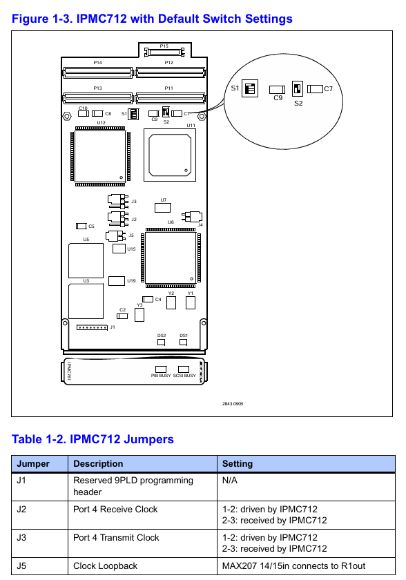
IPMC712: J1 (reserved programming interface), J2/J3 (port 4 clock source), J5 (clock loop back);
IPMC761: J1 (reserved), J2/J3 (source of clock for port 3/4 transmission and reception).
(2) Installation specifications
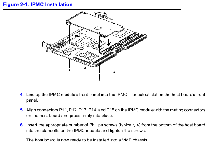
Installation position: Only supports installation in PMC slot 1 of the host. Before installation, the filler plate of the host front board needs to be removed to ensure that the module front board is aligned with the host front board;
Static protection: An anti-static wristband must be worn, and the module should be stored in anti-static packaging to avoid touching the circuit board pins;
Mechanical fixation: Fix the module on the host bracket with 4 M2 screws, ensuring that connectors P11-P15 are fully engaged with the host socket;
EMI compliance: After installation, ensure that all panel openings of the host are covered by modules or filler boards to avoid electromagnetic interference leakage.
Programming and Compatibility
(1) Core points of programming
PCI device configuration:
The onboard PCI device includes a SCSI controller (vendor ID 0x1000, device ID 0x0012) and a PCI-ISA bridge (vendor ID 0x10A, device ID 0x0565), which require setting interrupt and DMA parameters through the PCI configuration space;
IDSEL address mapping: Ensure device enumeration uniqueness based on the host model corresponding to AD11 (MVME5100/5500) and AD16/AD21 (MVME6100).
Interrupt and DMA configuration:
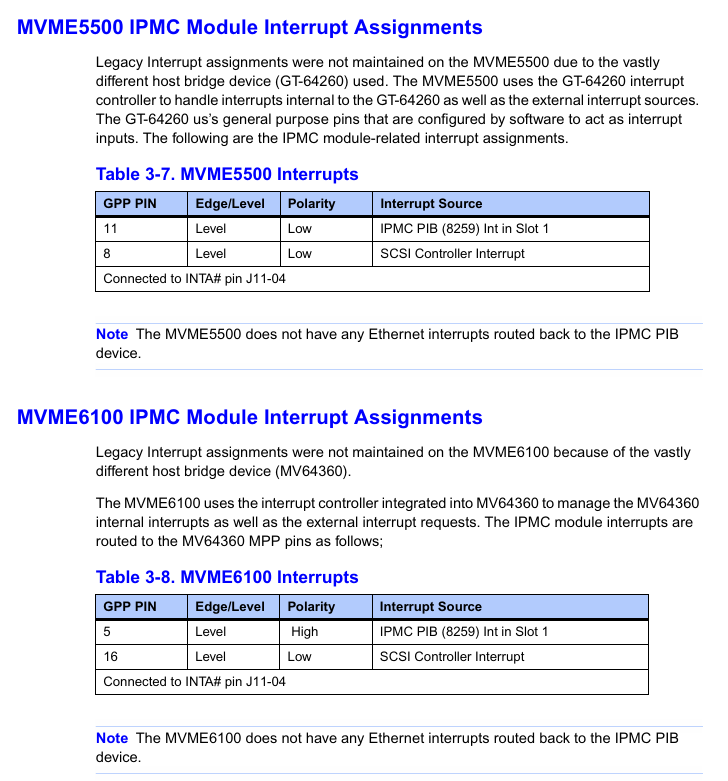
Interrupt routing: SCSI interrupts (IRQ14) and serial/parallel interrupts (IRQ3/4/7/9/10) are bridged to the host MPIC (Multiprocessor Interrupt Controller) through PIB, with different interrupt pin assignments for different hosts (such as IRQ0/9 for MVME5100 and MPP5/16 for MVME6100);
DMA channels: Supports 7 ISA DMA channels, with channels 0/1/5/6 for serial port transmission and reception, channels 2/3 for parallel ports, and channel 4 for internal cascading.
VPD access: Access the onboard EEPROM (address 0xA4) through the I ² C bus to read configuration information such as module model and hardware version. The host needs to access it through the I ² C controllers of Hawk (MVME5100), GT-64260 (MVME5500), and MV64360 (MVME6100).
(2) System compatibility
Adaptation host: Only supports MVME5100, MVME5500, and MVME6100 single board computers, and S2 switch and interrupt mapping need to be configured according to the host model;
Backward compatibility: Supports replacing old MVME761/MVME712M modules and achieving I/O signal compatibility through P2 transition cables, but attention should be paid to some PMC I/O routing restrictions (such as IPMC712 not supporting backplane Ethernet);
Software support: Compatible with Motorola PowerPlus II architecture programming specifications, requiring the use of firmware tools such as MOTLoad and PPCBug for configuration and debugging.
Environmental adaptability and compliance certification
(1) Environmental parameters
Environmental category specification requirements
Temperature operation: 0~70 ℃ (compliant with IEC 60068-2-1/2); Storage: -40~85 ℃ (compliant with MIL-STD-810G)
Humidity 20%~95% (40 ℃ without condensation, in accordance with IEC 60068-2-78)
Vibration and shock operation vibration: 5~60Hz (0.137mm), 60~150Hz (1.0G, in accordance with IEC 60068-2-6); Storage impact: 15G (11ms, compliant with IEC 60068-2-27)
The protection level module body is IP20 (compliant with IEC 60529) and needs to be installed in control cabinets with a protection level of IP54 or higher
(2) Compliance certification
Electromagnetic compatibility (EMC): compliant with EN 55022 Class B, EN 61000-6-2/4, resistant to ESD (± 8kV air discharge), surge (± 2kV communication port);
Safety certification: CSA ordinary area certification, Class I Division 2 Groups A-D hazardous area (non flammable);
Environmental Compliance: Compliant with RoHS Directive (Restriction of Hazardous Substances) and WEEE Directive (Electronic Waste Recycling).
Precautions for use
SCSI signal conflict: When installing other modules in host PMC slot 2, it is important to note that there may be conflicts with the SCSI signal (P15 connector), and the redundant signal should be disconnected through a 0 Ω resistor (R92-R100);
Clock configuration: The serial port clock source needs to be strictly matched through jumper wires (such as distinguishing between "module driver" or "external input" for IPMC712 port 4 clock) to avoid communication abnormalities;
Firmware and documentation: The module needs to be used in conjunction with the host firmware (such as the Hawk ASIC firmware of MVME5100). It is recommended to refer to the host manual to confirm the details of interrupt and DMA configuration.
- YOKOGAWA
- Reliance
- ADVANCED
- SEW
- ProSoft
- WATLOW
- Kongsberg
- FANUC
- VSD
- DCS
- PLC
- man-machine
- Covid-19
- Energy and Gender
- Energy Access
- Renewable Integration
- Energy Subsidies
- Energy and Water
- Net zero emission
- Energy Security
- Critical Minerals
- A-B
- petroleum
- Mine scale
- Sewage treatment
- cement
- architecture
- Industrial information
- New energy
- Automobile market
- electricity
- Construction site
- HIMA
- ABB
- Rockwell
- Schneider Modicon
- Siemens
- xYCOM
- Yaskawa
- Woodward
- BOSCH Rexroth
- MOOG
- General Electric
- American NI
- Rolls-Royce
- CTI
- Honeywell
- EMERSON
- MAN
- GE
- TRICONEX
- Control Wave
- ALSTOM
- AMAT
- STUDER
- KONGSBERG
- MOTOROLA
- DANAHER MOTION
- Bentley
- Galil
- EATON
- MOLEX
- Triconex
- DEIF
- B&W
- ZYGO
- Aerotech
- DANFOSS
- KOLLMORGEN
- Beijer
- Endress+Hauser
- schneider
- Foxboro
- KB
- REXROTH
- YAMAHA
- Johnson
- Westinghouse
- WAGO
- TOSHIBA
- TEKTRONIX
- BENDER
- BMCM
- SMC
- HITACHI
- HIRSCHMANN
- XP POWER
- Baldor
- Meggitt
- SHINKAWA
- Other Brands
- UniOP
- KUKA
- IBA
- Beckhoff
- ADLINK
-
ADLINK HPCI-14S12U - Industrial Control Backplane 12PCI Backplane PCI-14S Passive Backplane
-
ADLINK PCIe-GIE74C - image acquisition card 4-CH GigE Vision PoE+ Frame Grabber
-
ADLINK PCI-8164 - control card 4-Axis Advanced Motion Controller Board
-
ADLINK PCIe-U304 - 4 Port USB3 PCIe Frame Grabbers USB Screw Hole Card
-
ADLINK PCI-9112 - Multi-Function Data Acquisition Card DAQ Card
-
ADLINK PCI-7432 - 51-12013-0A50 4-CH Isolated Numérique I/O PCI Cartes Digital I/O Card
-
ADLINK PCA-6106P3-0C1 REV.C1 - backplane 6-Slot Passive Backplane Board
-
ADLINK PCI-7224 - 24-CH Opto-Isolated Digital I/O PCI Board
-
ADLINK CPCI-7433R(G) - Digital Input Board Rear I/O CompactPCI Card
-
ADLINK EBP-13E4 - 51-46703-0A30 Industrial PC Backplane Passive Backplane
-
ADLINK PCIE-HDV62 - Image acquisition card High Definition Video Frame Grabber
-
ADLINK EBP-13E4 - 51-46703-0A30 Industrial Backplane Board Passive Backplane
-
ADLINK 90111-B1 / CPCI-6770 - PCB CPU MODULE CompactPCI Single Board Computer
-
ADLINK PCI-7248 - DATA ACQUISITION PCI CARD 48-CH Parallel Digital I/O Board
-
ADLINK PCI-7230 - 51-12003-0a50 board PCI7230 32-CH Isolated Digital I/O Card
-
ADLINK PCI2A000CB - 51-20000-0B30 Multi-Function DAQ Card Baseboard
-
ADLINK PCI-8134-005 - 4-Axis Motion Controller Card
-
ADLINK PCI-7224 - 24-CH Opto-Isolated Digital I/O PCI Card
-
ADLINK PCI-7434 - 64-CH Isolated Digital Output Card
-
ADLINK PCI-8132 - motion control card 2-Axis Servo & Stepper Controller
-
ADLINK PCI-8134 - Motion Controller PCI Card 4-Axis Controller Board
-
ADLINK PCI-8164 - Motion Control Card 51-12406-0A40 4-Axis Controller
-
ADLINK 51-12001-0C20 - Circuit Board Data Acquisition Interface Module Hardware
-
ADLINK NuPR0-840 - industrial control motherboard Full-Size PICMG CPU Board
-
ADLINK PCI-7444 - 51-12023-0A10 card 128-CH Isolated Digital Output Board
-
ADLINK PCI-1612B - data acquisition card 4-Port RS-232/422/485 Serial Communication Card
-
ADLINK PCI-6208V 009 - 8/16-CH 16-Bit Analog Output Cards PCB-I-E-482=6BX3
-
ADLINK NUPRO-935A/LV - industrial control motherboard Full-Size PICMG SBC Board
-
ADLINK PCI-9114DG - Multi-Function DAQ Card Data Acquisition PCI Card
-
ADLINK ACL-7130 - Data acquisition card Isolated Digital I/O Board
-
ADLINK ABX-6300D-4E1-BP - board ABX6300D4E1BP Video Interface Expansion Card
-
ADLINK CPCI-6940 - CPCI-6940/D1539/M16-0(EA)-000E 6U CompactPCI Processor Board
-
ADLINK NuPRO-760 - industrial control motherboard Half-Size PICMG SBC CPU Board
-
ADLINK IMB-M42H (G)-0020 - industrial control motherboard LGA1155 Micro-ATX Mainboard
-
ADLINK RTV-24 / PCI-MP4S - 51-12519-1C30 4-Channel Real Time Video Capture Board
-
ADLINK PCI-8134 - 4-Axis Servo & Stepper Motion Controller Card
-
ADLINK MXC-6101D - V.PC000.002.ST.00 Box PC Configurable Embedded Computer
-
ADLINK PCI-8134A - 51-12421-0A10 Motion Control Card 4-Axis Controller Card
-
ADLINK DIN-100S / DIN-100SA1 - Technology SCSI-II TB 100-PIN Terminal Block Board
-
ADLINK DIN-812M001 / DIN812M001 - 51-14034-0A1 51140340A1 Terminal Module Breakout Interface
-
ADLINK PCI-8164 - Servo motion control 4-Axis Advanced Controller Card
-
ADLINK PCIe-GIE64 - Acquisition card GigE Vision PoE+ Frame Grabber
-
ADLINK M-302 - Industrial control motherboard ATX PC Board Mainboard
-
ADLINK PCI-8134 - Motion Controller PCI Card 4-Axis Controller Board
-
ADLINK PCI-RTV24 - Image capture card Analog Video Frame Grabber
-
ADLINK PCI-8102 - Motion control card 2-Axis Servo & Stepper Controller Board
-
ADLINK PCI-9112 REV.B1 - Card Multi-Function Data Acquisition Card
-
ADLINK HSI-DI32-M-N / HSL-TB32-M-DIN - Discrete I/O MODULE Distributed Automation Module System
-
ADLINK PCI-7296 - IO card REV.A3 96-CH Parallel Digital I/O Card
-
ADLINK DIN-814P-A4 / 814Y - terminal board Motion Control Interface Block
-
ADLINK DIN-814P-A4 - 51-14056-0A10 PCB-I-E-2736=ZA01 Screw Terminal Board Breakout
-
ADLINK M-322 - motherboard Industrial Control Computer Mainboard
-
ADLINK NUPRO-406 REV:B1 - industrial control motherboard Full-Size PICMG CPU Board
-
ADLINK AMP-204C - card DSP-Based 4-Axis Advanced Pulse-Train Controller
-
ADLINK HPCI14S REV.B1 - industrial computer baseboard 14-Slot Passive Backplane
-
ADLINK PCI-7250 - 8-CH Relay Output & 8-CH Isolated DI PCI Card
-
ADLINK EBP-13E2 - baseplate Passive Backplane Industrial Computer Chassis Board
-
ADLINK LPCI-3488A - PCI-GPIB card 51-12801-0A30 acquisition card IEEE-488 Interface Board
-
ADLINK PCI-6216V-GL - 51-12201-0C30 16-CH 16-Bit Voltage Analog Output Card
-
ADLINK ACL-8454 - 16-CH Isolated Digital I/O & 4-CH Counter Card
-
ADLINK HPCI-9S7U - backplane Passive Backplane Compatible with NuPRO-A301 852 841 842
-
ADLINK DAQ-2010-007 - Simultaneous-Sampling Multi-Function Data Acquisition Card
-
ADLINK MP-C154 - 51-64205-0A10 Motion Control Card 4-Axis Controller Board
-
ADLINK MXE-202/mSSD16B/WiFi-BT - Matrix Rugged I/O Platform Embedded Fanless Computer
-
ADLINK CM-920-R-17 - PC/104-Plus Single Board Computer Module Intel Celeron M
-
ADLINK PCI-7250 NSMP - 8-CH Relay Output & 8-CH Isolated DI Card
-
ADLINK PCI-8164 - 4-Axis Motion Controller PCI Card W/ Cable and Breakout Box
-
ADLINK EMX-100 - Ethernet-based 4-axis Motion Controllers Distributed Motion Module
-
ADLINK PCI-8134A - Press control card 4-Axis Motion Controller Board
-
ADLINK M-845EG REV:3.2 - industrial motherboard Pentium 4 Socket 478 Micro-ATX
-
ADLINK PCI-9114A Rev A2 DG - card High-Resolution Multi-Function Data Acquisition Board
-
ADLINK IEC-915GV - REV 1.1 Industrial motherboard Socket 478 CPU Board
-
ADLINK PCI-9111DG(G) - Data Acquisition Card Multi-Function DAQ Card
-
ADLINK HPCI-15S10 REV:B2 - Industrial computer base plate Passive Backplane Board
-
ADLINK NuPR0-840 / NuPR0-840DV - industrial control motherboard Full-size PICMG CPU Board
-
ADLINK RTV-24 / PCI-MP4S - 51-12519-1C30 4-Channel Real Time Video Capture Board
-
ADLINK NUPRO-780 - industrial control motherboard Pentium III Single Board Computer
-
ADLINK PCI-7296 - 0050 card 96-CH Opto-Isolated Parallel DIO Card Set
-
ADLINK NUPRO-780 - industrial control motherboard PICMG Full-Size SBC
-
ADLINK PCI-7248 - 51-12006-0A3 002 Pci 7248 48-CH Parallel Digital I/O Card
-
ADLINK PCI-7230 - 32-CH Isolated Digital I/O Card
-
ADLINK AMP-204C - motion control card 4-Axis Advanced Controller Board
-
ADLINK PCI-1714UL - Card Ultra High-Speed 4-CH Simultaneous Sampling DAQ
-
ADLINK NuPRO-E330 - industrial computer equipment motherboard PICMG 1.3 SHB SBC
-
ADLINK AMP-204C - DSP-Based 4-Axis Advanced Pulse-Train Motion Controller Module
-
ADLINK PCI-7256 - 001 51-12206-0A2 REV.A2 LPCI-7256 16-CH Latching Relay Output Card
-
ADLINK ND6050 - NUDAM DIGITAL I/0 MODULE Distributed I/O Unit
-
ASEM BM100 - Box PC Embedded Fanless Industrial Computer
-
ADLINK PCI-7250 - PCI Acquisition Card 8-CH Relay Output & Isolated DI Board
-
ADLINK PCI-8164 - Servo motion control 4-Axis Controller Card
-
ADLINK NuPRO-A40H - Industrial Motherboard 51-41807-1A30 OSP LGA1155 H61
-
ADLINK ADMAX X300 SERVER - 51066010-0A30 motherboard Multi-Processor Mainboard
-
ADLINK CMe-GIE62+ - 51-32903-0A30 control card PC/104-Plus GigE Vision Frame Grabber
-
ADLINK NUPRO-780 - industrial control motherboard Full-Size PICMG SBC CPU Board
-
ADLINK ETX-AT-N270-18/GKTEL - 51-71111-OB10 motherboard ETX CPU Module Board
-
ADLINK DIN-812M - interface module Terminal Block Connection Board
-
ADLINK IMB-M42H - industrial control motherboard LGA1155 Micro-ATX Mainboard
-
ADLINK PXIS-2508 - 8-slot 3U PXI Instrument Chassis Power Hardware Assembly
-
ADLINK AMP-208C - Motion Control card DSP-Based 8-Axis Pulse-Train Controller
-
ADLINK PCI-9111 / PCI-9111DG - Multi-Function Data Acquisition Card DAQ Board
-
ADLINK IEEE-488 GPIB card - Bus Interface Controller Communication Board
-
ADLINK RTV-24 - 51-12519-1C30 image acquisition card Video Frame Grabber Card
-
ADLINK TB-24P/24-01 - Board 24 Way Screw Terminal Breakout Board
-
ADLINK HSL-DI16DO16-DB-NN - 51-23015-0A40 Distributed Discrete I/O Module Set
-
ADLINK PCI-7442 - switch quantity card data acquisition card 64-CH Isolated Card
-
ADLINK ACL-7130 REV. B2 - industrial control capture card Isolated Digital I/O PCI Card
-
ADLINK PCI-6S / PCI6S - Backplane 6-Slot Passive Backplane Chassis Board
-
ADLINK ACL-8113A - card Isolated Digital Input Card
-
ADLINK CPCI-6208V-003 - board cPCI CompactPCI 8-CH Analog Output Card
-
ADLINK DIN-100S-01(G) - SCSI 100-Pin Terminal Block Interface Board
-
ADLINK PCI-7433 - Isolated Digital Input Card 64-CH
-
ADLINK PCI-9812 - Synchronous sampling analog input card High-Speed DAQ Board
-
ADLINK PCI-7434 REV.B1 - PLOTECH PCB-I-E-1182=6EX2 64-CH Isolated Digital Output Card
-
ADLINK PCIe-RTV24 - 51-18016-0A20 4-CH Real-Time Video Capture Card PCIe Frame Grabber
-
ADLINK PCI-8144 / PCI-8144N - Motion control card 4-Axis Stepper Motor Controller
-
ADLINK DIN-68S-01 - terminal board 68-Pin Connector Terminal Block
-
ADLINK MP-C154 - Motion control card 4-Axis Advanced Controller Card
-
ADLINK PCI-7248 (G) - Motherboard 48-CH Parallel Digital I/O Card
-
ADLINK MXE-1301(G) - Intel Atom D2550+NM10 MXE 1300 Series 93-4130-0030 Embedded Computer
-
ADLINK PRO-841 Rev 2.0 / PRO-060907000670 - CPU 2.26GHz & RAM Industrial PC Board
-
ADLINK cPCI-6626 - 6U CompactPCI 2.0 Blades i7-2710QE PCB-I-E-2570=9N41
-
ADLINK MXC-6322D(G) - Industrial Fanless Computer
-
ADLINK cPCI-8168-004 - CompactPci NulPC Motion Control Board 51-36402-0A3
-
ADLINK CPCI-7300[G] - COMPACTPCI Digital I/O Card Data Acquisition
-
ADLINK CPCI-6626/2710/M4G - COMPACTPCI COMPUTER BOARD
-
ADLINK cPCI-8168-009 - cPCI NulPC Motion Control Board
-
ADLINK cPCI-6626/2710/M4G - VME CPU Board Computer Board
-
ADLINK CPCI-R6200(G)-0040 - COMPACTPCI CONTROL BOARD

K-JIANG

Add: Jimei North Road, Jimei District, Xiamen, Fujian, China
Tell:+86-15305925923