

K-WANG


BENDER ISOMETER ® IRDH265/365 series insulation monitoring equipment
BENDER ISOMETER ® IRDH265/365 series insulation monitoring equipment
Product Overview
BENDER ISOMETER ® The IRDH265/365 series is an insulation monitoring device developed by Bender, a German company, specifically for IT AC systems, IT AC systems with directly connected DC circuits, and IT DC systems (isolated power supplies). Its core mission is to monitor the insulation resistance status between system conductors and the earth (PE) in real time, and to provide timely warning of insulation faults through a graded alarm mechanism, ensuring the safe and stable operation of electrical systems under complex working conditions. This series of products, with patented measurement technology, flexible adaptability, and comprehensive functional configuration, are widely used in industrial scenarios containing rectifiers, converters, thyristor controlled DC drivers, and other components. They fully comply with multiple international universal standards and have high reliability and strong compatibility.
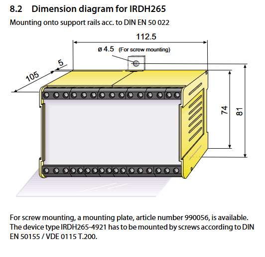
The series includes two core models: IRDH265 (standard plastic housing, supporting DIN rail installation or screw installation) and IRDH365 (embedded housing, 144x72mm size, compatible with panel embedded installation). The functional parameters of the two are the same, with only differences in installation methods and mechanical specifications, which can meet the needs of different installation scenarios.
Core adaptation range
(1) System type adaptation
Basic adaptation system: IT communication systems such as 3AC, 3 (N) AC, single-phase AC, etc; Pure IT DC system
Special adaptation system: IT AC system with direct connection to DC circuit (such as AC system with DC load including rectifier, converter, thyristor controlled DC driver, etc.)
Adaptation prerequisite: In the DC circuit directly connected to the AC system, the rectifier needs to carry a load current of>5... 10mA to ensure accurate monitoring of DC circuit insulation faults
(2) Voltage parameter specifications
Rated monitoring voltage: AC 0... 793V (frequency 50... 400Hz, reference to characteristic curve when frequency<50Hz); DC 0... 650V (slightly different sub series, such as -7 series DC maximum 750V, -8 series DC maximum 650V)
Extended monitoring voltage: It can be extended to higher levels through a dedicated coupling device, with specific adaptations as follows:
AGH204S-4: Suitable for AC 0... 1650V (without rectifier), AC 0... 1300V (with rectifier, DC maximum 1840V)
AGH520S: Suitable for AC 0... 7200V
AGH150W-4: Suitable for DC 0... 1760V
Power supply voltage requirements: Provide multi specification power supply adaptation to meet the power supply needs of different scenarios:
Power type, voltage range, applicable model examples
AC power supply 230V (50... 60Hz) IRDH265-4, IRDH365-4
AC power supply 90... 132V IRDH265-413, IRDH365-413
AC power supply 400V IRDH265-415, IRDH365-415
AC power supply 500V IRDH265-416, IRDH365-416
DC power supply 19.2... 84V IRDH265-422, IRDH365-422
DC power supply 77... 286V IRDH265-423, IRDH365-423
DC power supply 10.5... 80V IRDH265-R421, IRDH265-4921
Power protection: The power input terminal should be equipped with a short-circuit protection device according to the IEC 60364-4-473 standard, and it is recommended to use a 6A fuse
Core technology and functional characteristics
(1) Measurement principle (four levels optional to meet different system requirements)
AMP measurement principle (default): Bender's patented "adaptive measurement pulse" technology superimposes a pulsating AC measurement voltage with a peak value of 27V (positive and negative pulse amplitudes are consistent), and the measurement period dynamically adjusts with the system's leakage capacitance and insulation resistance. It is suitable for AC/DC hybrid systems, especially for complex scenarios containing a large number of DC components, with a maximum measurement current of 230 μ A.
DC measurement principle: Overlay 27V DC measurement voltage, only applicable to pure AC systems, insufficient sensitivity for DC insulation fault monitoring, not recommended for use in hybrid systems.
UG/AMP measurement principle: Passive asymmetric measurement (without DC measurement voltage), only applicable to pure DC systems. Fast response is achieved by detecting the DC current and residual voltage generated by L+/L - asymmetric faults. After the alarm is triggered, it automatically switches to the AMP principle to measure insulation resistance. AMP measurement is performed every hour to detect symmetric faults.
AMP/UG measurement principle: AMP measurement is combined with asymmetric measurement. The faults detected by AMP principle are fed back through ALARM2, while those detected by asymmetric measurement are fed back through ALARM1. It is suitable for scenarios that require differentiation of different fault types.
(2) Basic core functions
Insulation monitoring and graded alarm:
Dual level adjustable response values: -3 series 40k Ω/10k Ω, -4 series 180k Ω/40k Ω, -7 series 600k Ω/300k Ω, -8 series 1M Ω/500k Ω (all factory default, adjustable through menu, -3/-4 series adjustment range 10k Ω... 990k Ω), with a hysteresis of approximately 25%.
Fault type differentiation: Supports identification of AC faults and DC faults (including L+/L - single pole faults), and alarm triggering conditions can be set through the Setup 2 menu (only AC, only DC, both AC/DC triggered, etc.).
Alarm output: 2 conversion contact relays, supporting N/O (default) or N/C operation modes, rated contact voltage AC 250V/DC 300V, maximum switching current 5A, adjustable flashing function (1Hz pulse frequency).
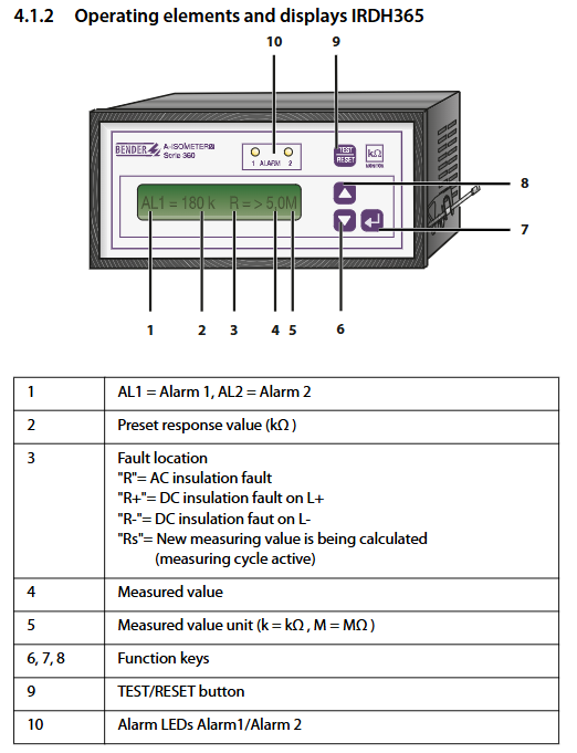
Alarm indication: Two yellow alarm LEDs (ALARM1/ALARM2), corresponding to two levels of alarms, will light up intuitively when there is a fault.
Automatic adaptation and self-monitoring:
Leakage capacitance adaptation: The -3/-4 series can adapt to a maximum of 500 μ F, while the -7/-8 series can adapt to a maximum of 2 μ F. The equipment automatically adapts to changes in system leakage capacitance without affecting measurement accuracy.
Automatic self-test: The -3/-4 series automatically performs a self-test every 24 hours (with the alarm relay set to system fault alarm mode), triggered when the insulation resistance exceeds 20 times the maximum response value.
Manual self-test: Press and hold the TEST button (>2s) to start. When there are no faults, it displays "TEST OK R<1k Ω", the alarm relay acts, and the LED lights up; When a fault is detected, it displays "TEST ALARM". Press the RESET button (<1s) to clear the fault indication.
Connection monitoring: The -3/-4 series comes standard with a connection monitoring function that continuously monitors the connection status between the device and the IT system or PE. When there is a disconnection or high resistance, it displays "ALARM E-KE" (PE connection fault) or "ALARM L1-L3" (system connection fault), which can be turned off in the Setup 2 menu (recommended for new or small systems).
Display and operation:
Display configuration: LCD display screen, supporting the display of measurement values (unit k Ω/M Ω), response values, fault types (R=AC fault, R+=L+fault, R -=L - fault), menu parameters, etc.
Operation buttons: Both IRDH265/365 are equipped with function buttons (parameter adjustment, menu switching) and a combination TEST/RESET button (short press reset, long press test), supporting external test/reset buttons (cable length ≤ 10m).
Parameter storage: Set parameters to be stored in non-volatile memory (EEPROM) without loss during power failure; Short circuiting the LT terminal can store fault indications, and no faults are stored when the terminal is disconnected.
(3) Extended functions (configured through the Setup 2/Setup 3 menu)
Menu grading configuration:
Setup 1 (basic function): Set alarm response values, relay operation modes (N/O/N/C), password query, jump to Setup 2.
Setup 2 (Extended Function): Configure alarm fault types, coupling device parameters, connection monitoring switches, alarm flashing function, relay test switches, alarm time delay (1... 10s), maximum leakage capacitance matching, password activation and modification, restore factory settings, and view software versions.
Setup 3 (Measurement Principle): Select the measurement principle (AMP/DC/UG/AMP/AMP/UG) and set the DC fast response current level (0.1... 5mA).
Password Protection: Supports activating a two letter password to prevent unauthorized modification of parameters. Passwords can be set and reset in the Setup 2 menu.
System fault handling: When the LCD displays "TEST ALARM", the device needs to be powered off for a moment before restarting. If the fault still exists, it is highly likely to be a fault of the device itself and requires maintenance.
Status word display: Press and hold the IRDH265 function key for ≥ 5 seconds to display the status word, which includes key configuration information such as relay mode, alarm function, connection monitoring status, measurement principle, etc.
(4) Interface and communication functions
RS-485 interface: No electrical isolation, compliant with EIA R5-485 standard, terminal A/B wiring, maximum transmission distance of 1200m, transmission protocol of 9600 Baud (1 start bit+8 data bits+1 stop bit), continuous transmission of measurement values, alarm status and other data blocks, cannot be interrupted by other bus members.
External indication interface: The M+/M - terminal supports external k Ω measuring instruments (0... 400 μ A analog output), and this interface has no electrical isolation. When connecting to the process control system, an additional isolation module (such as RK170) needs to be configured.
Mechanical specifications and environmental adaptability
(1) Mechanical specifications
Model shell type, installation method, panel opening size (mm), compatible wire specifications, protection level, weight
IRDH265 XM112 (halogen-free) DIN rail installation (DIN EN 50022) or screw installation (accessory 990056 required) - rigid conductor 0.2... 4mm ², flexible conductor 0.2... 2.5mm ² (compatible with AWG 24... 12) shell IP30, terminal IP20 approximately 825g
IRDH365 X300 (halogen-free) embedded installation 138 × 66 rigid conductor 0.2... 4mm ², flexible conductor 0.2... 2.5mm ² (compatible with AWG 24... 12) shell IP30, terminal IP20 approximately 1075g
Installation note: Only one active ISOMETER is allowed to be connected to each interconnected system in the IT system ®; Terminals E and KE need to be connected to PE through separate wires, and this connection cannot be disconnected during equipment operation; The installation distance between adjacent devices should be ≥ 10mm (ventilation gap should be reserved when the temperature is>40 ℃).
(2) Environment and anti-interference performance
Working temperature: -10...+55 ℃ (standard version), -15...+55 ℃ (some models), -25...+70 ℃ (T option version)
Storage temperature: -40...+70 ℃ (standard version), -45...+85 ℃ (T-option version), display screen function is only guaranteed above -40 ℃
Climate grade: IEC 60721-3-3 3K5 (no condensation, no icing)
Anti interference performance: compliant with EN 50082-2 (anti electromagnetic interference), EN 55011/CISPR11 (electromagnetic emission, Class A, Suitable for industrial scenarios)
Mechanical anti-interference: anti impact 15g/11ms (standard version), 30g/11ms (T-option version); Anti collision 40g/6ms; Anti vibration 10... 150Hz/0.15mm-2g (standard version), 1.6mm/10-25Hz+4g/25... 150Hz (T-option version)
Flame retardant rating: XM112 shell UL94V-0, X300 shell UL94V-1
- YOKOGAWA
- Reliance
- ADVANCED
- SEW
- ProSoft
- WATLOW
- Kongsberg
- FANUC
- VSD
- DCS
- PLC
- man-machine
- Covid-19
- Energy and Gender
- Energy Access
- Renewable Integration
- Energy Subsidies
- Energy and Water
- Net zero emission
- Energy Security
- Critical Minerals
- A-B
- petroleum
- Mine scale
- Sewage treatment
- cement
- architecture
- Industrial information
- New energy
- Automobile market
- electricity
- Construction site
- HIMA
- ABB
- Rockwell
- Schneider Modicon
- Siemens
- xYCOM
- Yaskawa
- Woodward
- BOSCH Rexroth
- MOOG
- General Electric
- American NI
- Rolls-Royce
- CTI
- Honeywell
- EMERSON
- MAN
- GE
- TRICONEX
- Control Wave
- ALSTOM
- AMAT
- STUDER
- KONGSBERG
- MOTOROLA
- DANAHER MOTION
- Bentley
- Galil
- EATON
- MOLEX
- Triconex
- DEIF
- B&W
- ZYGO
- Aerotech
- DANFOSS
- KOLLMORGEN
- Beijer
- Endress+Hauser
- schneider
- Foxboro
- KB
- REXROTH
- YAMAHA
- Johnson
- Westinghouse
- WAGO
- TOSHIBA
- TEKTRONIX
- BENDER
- BMCM
- SMC
- HITACHI
- HIRSCHMANN
- XP POWER
- Baldor
- Meggitt
- SHINKAWA
- Other Brands
- UniOP
- KUKA
- IBA
- Beckhoff
- ADLINK
-
ABB 3BHE039724R2643 PPD513 AC 800PEC High-Speed Controller for Power Electronic and Excitation Control Systems
-
SHINKAWA FRP 360A - BOARD
-
SHINKAWA IBP-43AM - PCB Board
-
SHINKAWA IBP-42-M - PCB Board
-
SHINKAWA DSP-11C - PCB Board
-
SHINKAWA FRP-341E - BOARD
-
SHINKAWA CPP-111 - PCB Board
-
SHINKAWA FRP-342A - BOARD
-
SHINKAWA FRP-341D - BOARD
-
SHINKAWA MDP-X MDP-135 - PCB Board
-
SHINKAWA MGP-57 - BOARD
-
SHINKAWA FRP-226A - PCB Board
-
SHINKAWA MDP-141 - PCB Board
-
SHINKAWA IOP-188 - BOARD
-
SHINKAWA FRP-341C - BOARD
-
SHINKAWA MDP-90 - PCB Board
-
SHINKAWA CPP-107A - PCB Board
-
SHINKAWA FRP-227A - PCB Board
-
SHINKAWA FRP-249A - PCB Board
-
SHINKAWA MDP-74 - PCB Board
-
SHINKAWA FRP-270 FRP-268 - PCB Board
-
SHINKAWA FRP-386 - PCB Board
-
SHINKAWA ZUP-02C - BOARD
-
SHINKAWA MDP-136A - PCB Board
-
SHINKAWA FRP-259 - PCB Board
-
SHINKAWA JBP-470 - BOARD
-
SHINKAWA MDP-82 - BOARD
-
SHINKAWA FCP-07A - PCB Board
-
SHINKAWA DSP-09A - PCB Board
-
SHINKAWA IOP-178 - PCB Board
-
Nemic-Lambda / Shinkawa VS15C-15 CCB010A UTC-1000 - Power Supply Board
-
SHINKAWA IOP-176A - PCB Board
-
SHINKAWA VM-5C SST-2194-001-P001G - ECCENTRICITY MONITOR
-
SHINKAWA VM-5K SST-2194-001-P001G - VIBRATION MONITOR
-
THK / Shinkawa SRS9M UTC-1000 - Linear Block w/ Rail 26cm
-
Shinkawa JBP-316 P-26-73B-1 P-26-73A-1 UTC-1000 - Board
-
SHINKAWA IOP-215 - BOARD
-
SHINKAWA JBP-268 - PCB Board
-
SHINKAWA ZUP-08 - PCB Board
-
SHINKAWA BCP-05A - BOARD
-
SHINKAWA DSP-15 - PCB Board
-
SHINKAWA FRP-289 - PCB Board
-
SHINKAWA FCP-01 - BOARD
-
SHINKAWA MDP-84 - BOARD
-
SHINKAWA CMU-13A - CAMERA MOTION CONTROLLER
-
SHINKAWA BCP-05D - PCB Board
-
SHINKAWA MDP-FF MDP-87 - Stage Control Board
-
SHINKAWA FRP-342 - BOARD
-
SHINKAWA BCP-05C - BOARD
-
Shinkawa CMU-26A - Camera Control unit
-
SHINKAWA PSP-30 - Welding Machine Control Board
-
SHINKAWA EFU-24 - Spark Generator
-
Shinkawa CMU-27A - Camera Control unit
-
SHINKAWA CMU-44 - Camera Control Unit
-
THK / Shinkawa SRS9M UTC-1000 - Linear Block w/ Rail 21cm
-
TDK-Lambda / Shinkawa VS100B-24 VS100B24 UTC-1000 - Power Supply Board
-
SHINKAWA CMU-34 - Camera Control Unit
-
SHINKAWA FDP-06A - PCB Board
-
SHINKAWA BCP-06A - BOARD
-
SHINKAWA CMU-13A - Camera Control Unit
-
SHINKAWA CMU-31A - Camera Control Unit
-
SHINKAWA VM-5Y1-02/GEM 1594-005-P001G - ECCENTRICITY MONITOR
-
Shinkawa JBP-331 P-26-101B P-26-101A P26101A UTC-1000 - Board
-
SHINKAWA CMU-26 - Camera Control Unit
-
Shinkawa ACB-3000 ACB3000 - Industrial-Grade Automated Friction Bonder
-
Shinkawa SBB-1100 SBB1100 - Stud Bump Bonder Machine
-
Shinkawa ACB-1000 ACB1000 - Super Automated Wire Bonder Machine
-
CKD / Shinkawa FCS500-H6H6 FCS500H6H6 UTC-1000 - Precision Air Source Filter
-
SHINKAWA VM-5H3 1596-001-P002B VM-5Z1 3595-001-P003C - Power Supply Monitor Rack
-
SHINKAWA VM-5H3 2194-001-F004B - Dual Vibration Dual Thrust Monitor Rack
-
Shinkawa EFU-10 - Wire Bonder Spark Generator EFO Box
-
SHINKAWA MP-2S - Overspeed Unit Instruction
-
Shinkawa PK-167B-3 PK-167A-3 10P-10 - PCB Board
-
SHINKAWA VM-3D VM-3E VL VM-3D2 - Vibration Sensor Mit Verlangerungskabel
-
shinkawa FKP-452F2-3 - Sensor
-
shinkawa UTC-1000 ZUP-02B - PCB BOARD
-
SHINKAWA VM-3D VM-3E VL VM-3D2 - VIBRATION SENSOR WITH EXTENSION CABLE
-
Shinkawa E194236-0003 AWM 2464 UTC-1000 - Cable 6&4 Pins Female-Female
-
TDK-Lambda / Shinkawa VS100B-15 VS100B15 UTC-1000 - Power Supply Board
-
Shinkawa FK-202F2-2-1 - Electric Vortex Sensor
-
Marubeni Shinkawa S038493 - Rotary Encoder
-
Shinkawa E194236-0003 AWM 2586 UTC-1000 - Cable 10 & 8 Pins Male-Female
-
National / Shinkawa CAT5E NR3160 UTC-1000 - Ethernet Receptacle Connector Cable
-
Shinkawa LLS2902 E69157 UTC-1000 - Cable 3 Pins Male-Female
-
Shinkawa AWG16 600V UTC-1000 - 5 Pins Cable Female-Female
-
SHINKAWA WK-142K2-2 - Vibration sensors
-
Shinkawa DA-C8-J10 DAC8J10 UTC-1000 - Connector Cable
-
Shinkawa P-27-67B P2767B P-27-67A P2767A UTC-1000 - Circuit Board
-
Taiyo / Shinkawa E67647-WH E67647WH UTC-1000 - Computer Power Cable
-
Shinkawa E66085-H 20276 UTC-1000 - Connector Cable 15 Pins Male-Male
-
Shinkawa P-28-49B JBP-380C P-28-49A BEJ240619A UTC-1000 - Board w/
-
Shinkawa WKN-142K2-2 - 2-Wire vibration transmitter
-
SHINKAWA VM-741 VM-741B - MONITORING SYSTEM
-
Shinkawa FL-202F08R-U2-02-12-10 - Extension probe
-
Shinkawa FK-202F-1-3 FK-202F-2-3 - module
-
Shinkawa CMU-13A CMU13A - Camera Motion Control Unit Cut Cable
-
SHINKAWA VM-5J - DUAL DIFFERENTIAL EXPANSION MONITOR
-
Ebrain / Shinkawa 650-VME08IS-S N6071085 UTC-1000 - Backplane Panel Board
-
Yaskawa Electric / SHINKAWA UGQMEM-06-SW12 MD-11 - Minertia Motor w/ 30 day warranty
-
Shinkawa FL-202F08R-U2-02-12-10 - Extension probe
-
Shinkawa WT-650-16 SP-256A UTC-1000 - Power Source Power Supply AC100V 50/60Hz
-
Yaskawa / Shinkawa UGRMEM-01SSW11 UGRMEM01SSW11 MD-06 - Minertia Motor
-
SHINKAWA FK-452F1 - sensor
-
Shinkawa MS-313 - RPS positioning system
-
Shinkawa Sec M / Rn-ac109-2a - Beschleunigungsmesser
-
Shinkawa PFD80SX UTC-1000 - Power Source Power Supply 80V 1.6A AC100-230V
-
SHINKAWA VL-202A08L-1A72 - Probe extension cable
-
Shinkawa SDP-FA-4.1 - Instruction Manual
-
SHINKAWA VM-5L G0-2 GC6D1377 - Module
-
Shinkawa FRP-184A FRP-111 P-22-17A - Circuit Board
-
Shinkawa CRP-06 PK-189A-3 PK-189B-3 - PCB Board
-
Shinkawa WK-142K2-1 - Vibration Transmitter
-
SHINKAWA VM-5 SST-2194-001-P001G - MAIN BOARD DUAL VIBRATION MONITOR MAIN BOARD
-
Shinkawa SDP-FA-TAPE - Full Automatic Die Bonder Instruction Manual
-
Sanritz Automation / Shinkawa SC2125-0 C12ABP3 SC2125-0-P1 UTC-1000 - Board
-
Shinkawa SDP-FA-4.1 - Die Pickup Unit Instruction Manual
-
Shinkawa E194236-0003 AWM 2464 UTC-1000 - Cable 20 Pins Female-Female
-
IHI / SHINKAWA CQ71SEN004 WK-142K3-3 - 2-wire Transmitter
-
SHINKAWA FK-452F1 - sensor
-
Shinkawa D461256 - Pin Vertical Motion Cam
-
SHINKAWA SE02111-05 STB-FA-IL-7 - Full Automatic Inner Lead Bonder Specifications
-
Shinkawa PSP-25A P-26-58A-3 P2658A3 UTC-1000 - Circuit Controller Board
-
Shinkawa WKN-142K5-2 - Vibration Transmitter
-
Euresys / Shinkawa DAC-422S-A3 DAC422SA3 UTC-1000 - Alpha cPCI Board
-
Shinkawa IL-188-5373-23 IL188537323 - Spare Part
-
Shinkawa FK-202F1-3-1 - Vibration sensor
-
Shinkawa VL-202A08L-1018/BEN - Capteur De Proximite Avec Cable De 9 Metres
-
Shinkawa FK-202F-2-3 - Vibration Transmitter

K-JIANG

Add: Jimei North Road, Jimei District, Xiamen, Fujian, China
Tell:+86-15305925923