
K-WANG


BENDER ISOMETER ® IRDH375 series Insulation Monitoring Equipment
BENDER ISOMETER ® IRDH375 series Insulation Monitoring Equipment
Product Overview
BENDER ISOMETER ® The IRDH375 series is an insulation monitoring device developed by Bender, a German company, specifically for ungrounded alternating current (AC), mixed AC/DC, and direct current (DC) systems (i.e. IT systems). Its core mission is to monitor the insulation resistance status between the system conductor and the ground in real time, warn of insulation faults in a timely manner, and ensure the safe and stable operation of electrical systems. This series of products, with patented measurement technology, flexible adaptability, and comprehensive functional configuration, are widely used in various scenarios with strict electrical safety requirements, and fully comply with multiple international universal standards, possessing high reliability and compatibility.
Core adaptation range
(1) System type adaptation
Basic adaptation systems: AC system, DC system, AC/DC hybrid main circuit
Special adaptation system: AC/DC main circuit with direct connection to DC components (such as rectifiers, converters, thyristor controlled DC drivers); UPS system, battery system; Phase controlled heater; Installation scenarios for equipment with switch mode power supply; High leakage capacitance IT system; Coupling IT systems
(2) Voltage parameter specifications
Rated monitoring voltage: AC/AC-DC 0... 793V, DC 0... 650V
Extended monitoring voltage: By combining with a dedicated coupling device, it can be extended to higher voltage levels such as DC 0... 1760V, 3/(N)/AC 0... 7200V (50... 400Hz), etc
Power supply voltage requirements:
AC power supply: 88... 264V (frequency 42... 460Hz)
DC power supply: 77... 286V or 19.2... 72V (please refer to the equipment nameplate for details)
Power protection: requires power supply through a 6A fuse; Mandatory requirement to use 5A fuses for UL and CSA application scenarios
Core technology and functional characteristics
(1) Measurement technology
Adopting the patented AMPPlus measurement method, designed specifically for modern power supply systems, it can accurately respond to complex scenarios containing a large number of directly connected DC components and high system leakage capacitors, effectively solving the problem of inaccurate monitoring by traditional measurement methods in such scenarios, and ensuring the stability and reliability of insulation resistance monitoring.
(2) Basic functions
Insulation monitoring core: Real time monitoring system insulation resistance, supporting two independent adjustable response values (1k Ω... 10M Ω), can set warning threshold and alarm threshold separately, achieving graded warning
Automatic adaptation capability: Without manual intervention, the device can automatically adapt to system leakage capacitance (maximum allowable value ≤ 500 μ F) and adapt to changes in system parameters under different operating conditions
Self monitoring and self testing:
Continuous self-monitoring: Real time inspection of the device's own working status, automatic triggering of system fault alarm in case of malfunction
Optional automatic self testing: supports manual self testing through the TEST button to verify device functionality and the connection status between the system and the earth
Display and operation:
Display configuration: Dual row backlit LCD display screen, supports switching between standard mode and menu mode, clearly displays insulation resistance value, device settings, fault information, etc
Operation buttons: equipped with four core buttons: INFO (query standard information), TEST (self-test), RESET (clear fault alarm), MENU (activate menu system), and support direction keys (up/down) and confirm key operation. Parameter configuration can be completed through panel buttons; Support external testing and reset buttons (cable length ≤ 10m)
Alarm function:
Alarm output: 2 independent alarm relays, both with passive conversion contacts, supporting N/O (normally open) or N/C (normally closed) operation modes; Additional configuration of system fault alarm relay (default N/C operation mode)
Alarm indication: 3 dedicated alarm LED lights, corresponding to "Level 1 Insulation Fault Warning", "Level 2 Insulation Fault Alarm", and "Equipment Self Fault", providing intuitive feedback on the alarm level
Fault storage: It can store fault information and clear it through the RESET button or external reset button (when terminals R1/R2 are disconnected and the storage function is not activated through the operation menu, the fault information is not stored)
Extension interface:
Communication interface: RS-485 interface (supports ASCII protocol), transmission distance ≤ 1200m (recommended to use J-Y (St) Y 2 × 0.8mm ² twisted pair, with one end of the shielding layer connected to PE), supports communication with external systems
External indicator interface: Reserve an external k Ω indicator interface (output 0... 400 μ A signal), which can be connected to external measuring instruments to display insulation resistance values
Terminal design: adopting plug-in terminals, convenient wiring, and terminal protection level up to IP30
Other auxiliary functions:
INFO button: Press to query additional information such as system leakage capacitance, current device settings, etc
Standby function: Controlled through function input ports F1 and F2, the device enters standby mode when the contacts are closed, pausing insulation measurement and achieving system disconnection control
DIP switch configuration: When the S1 switch is in the "ON" state, the RS-485 interface enables a 120 Ω terminal resistor; S2 switch has not yet been assigned a function
(3) Advanced features of IRDH375B (added compared to the base model)
Historical record storage: Built in historical memory with real-time clock, which can record all alarm information and attach date and time stamps for easy fault tracing and analysis
Enhanced Communication Capability: Equipped with an electrically isolated RS-485 interface, supporting BMS protocol, capable of stable communication with other Bender devices, and adaptable to centralized control scenarios such as building management systems
Coupling system adaptation: Built in insulation monitoring device disconnect relay, supports multiple IRDH375B devices to work together in the coupling IT system, and ensures that only one device is active at any time by controlling input ports F1/F2 to avoid monitoring conflicts
Analog output: Added 0 (4)... 20mA current output, which can be used for external data acquisition devices to achieve remote transmission and recording of insulation resistance data
Key performance parameters
Specific parameter specifications for performance categories
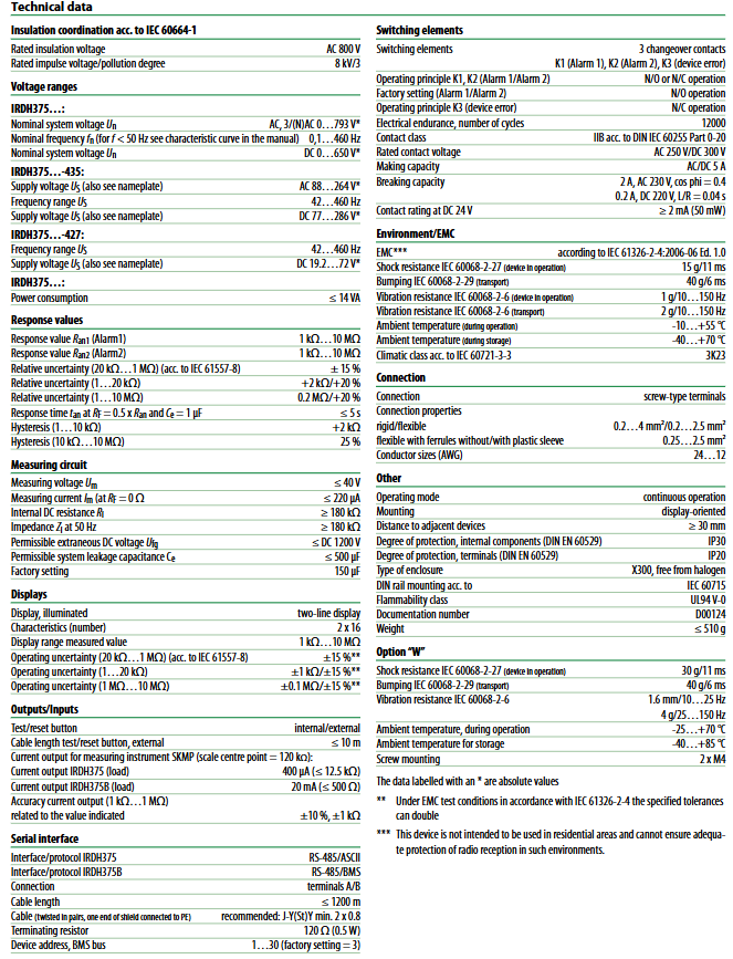
When the insulation resistance R_F=0.5 x the set response value R_an and the system leakage capacitance C_e=1 μ F, the response time is ≤ 5s
Measurement accuracy 1k Ω... 1M Ω Range: ± 15% ± 1k Ω; 1k Ω... 10M Ω Range: ± 15% ± 0.1M Ω (compliant with IEC 61557-8 standard)
Electrical durability contact category 12000 IIB (compliant with DIN IEC 60255 Part 0-20); Rated contact voltage AC 250V/DC 300V
Contact capacity AC/DC 5A; 2A at AC 230V, cos φ=0.4; 0.2A at DC 220V, L/R=0.04s; minimum control current ≥ 2mA (50mW)
Environmental adaptability working temperature: -10...+55 ℃ (regular model), -25...+70 ℃ (Option-W model); Storage temperature: -40...+70 ℃ (regular version), -40...+85 ℃ (Option-W version); Climate grade: IEC 60721-3-3 3K23
Anti interference and mechanical performance electromagnetic compatibility (EMC): compliant with IEC 61326-2-4:2006-06 Ed.1.0 standard; Impact resistance: IEC 60068-2-27 (15g/11ms); Anti collision (transportation): IEC 60068-2-29 (40g/6ms); Vibration resistance: IEC 60068-2-6 (1g/10... 150Hz, transportation scenario 2g/10... 150Hz); Option-W enhances impact resistance (30g/11ms) and vibration resistance (1.6mm/10-25Hz, 4g/25... 150Hz) performance
Mechanical specification panel opening size: 138 × 68mm; installation method: DIN rail installation (in accordance with IEC 60715 standard) or screw installation (2 × M4); Shell type: X300 type, halogen-free material; Protection level: IP20 for equipment casing; Weight ≤ 510g; distance between adjacent equipment installations ≥ 30mm
Wiring specification terminal type: spiral terminal; Conductor adaptation: rigid conductor 0.2... 4mm ², flexible conductor (with/without plastic sleeve) 0.2... 2.5mm ²; Suitable for AWG wire gauge: 24... 12; Terminal pairs 10, 11, and 12 must be electrically isolated and must not be connected to PE
Operation and Display Instructions
(1) Operation button function
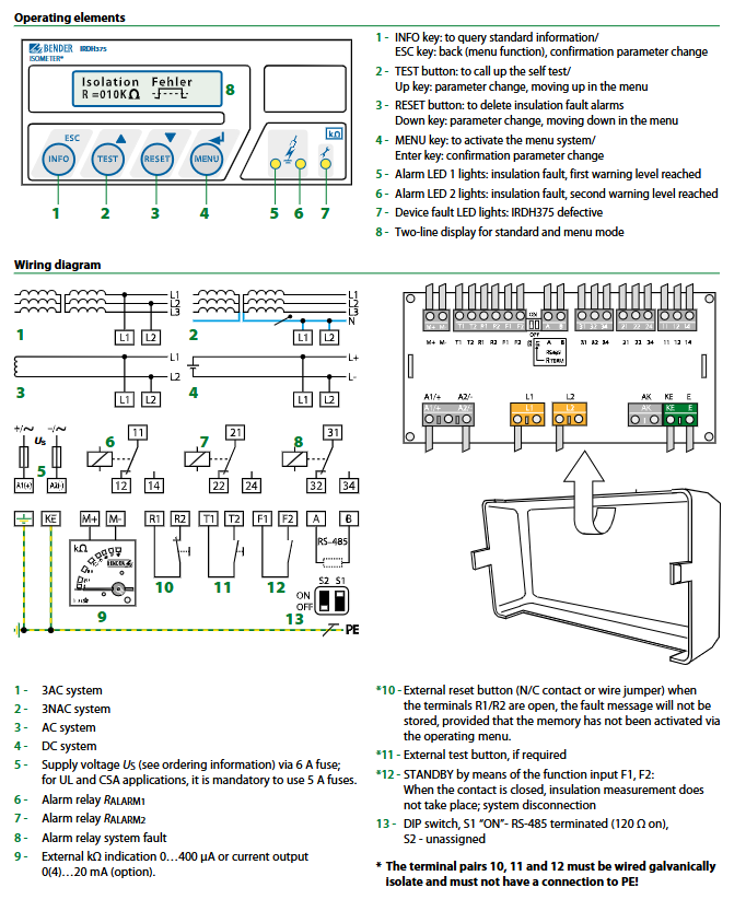
Core functions of buttons/operating components
INFO key to query standard information; Cooperate with menu operations to achieve function switching
Return to the previous level in ESC menu mode; Confirm parameter changes
Test button to start device self-test; As an up arrow key in menu mode, it is used for parameter changes and menu navigation
The RESET button clears the insulation fault alarm record; As the down arrow key in menu mode, it is used for parameter changes and menu navigation
MENU key activates the menu system; As a confirmation key in menu mode, confirm parameter changes
Alarm LED 1 lights up to indicate insulation fault, reaching the first level warning threshold
Alarm LED 2 lights up to indicate insulation fault, reaching the second level alarm threshold
Device fault LED lights up to indicate a device malfunction (IRDH375 malfunction)
Dual row display screen standard mode displays insulation resistance value and fault information; Menu mode displays parameter configuration interface
(2) Parameter configuration method
Support two parameter configuration methods: one is to operate through the dual row LCD display screen on the device panel in conjunction with functional buttons; The second is to connect to the external control system through the RS-485 interface for remote configuration (in accordance with the corresponding communication protocol). During the configuration process, changes can be confirmed through the ESC key or Enter key, and the operation logic is clear and easy to understand.
- YOKOGAWA
- Reliance
- ADVANCED
- SEW
- ProSoft
- WATLOW
- Kongsberg
- FANUC
- VSD
- DCS
- PLC
- man-machine
- Covid-19
- Energy and Gender
- Energy Access
- Renewable Integration
- Energy Subsidies
- Energy and Water
- Net zero emission
- Energy Security
- Critical Minerals
- A-B
- petroleum
- Mine scale
- Sewage treatment
- cement
- architecture
- Industrial information
- New energy
- Automobile market
- electricity
- Construction site
- HIMA
- ABB
- Rockwell
- Schneider Modicon
- Siemens
- xYCOM
- Yaskawa
- Woodward
- BOSCH Rexroth
- MOOG
- General Electric
- American NI
- Rolls-Royce
- CTI
- Honeywell
- EMERSON
- MAN
- GE
- TRICONEX
- Control Wave
- ALSTOM
- AMAT
- STUDER
- KONGSBERG
- MOTOROLA
- DANAHER MOTION
- Bentley
- Galil
- EATON
- MOLEX
- Triconex
- DEIF
- B&W
- ZYGO
- Aerotech
- DANFOSS
- KOLLMORGEN
- Beijer
- Endress+Hauser
- schneider
- Foxboro
- KB
- REXROTH
- YAMAHA
- Johnson
- Westinghouse
- WAGO
- TOSHIBA
- TEKTRONIX
- BENDER
- BMCM
- SMC
- HITACHI
- HIRSCHMANN
- XP POWER
- Baldor
- Meggitt
- SHINKAWA
- Other Brands
- UniOP
- KUKA
- IBA
- Beckhoff
-
Basler Electric DECS-250-CN1SN1N Automatic Voltage Regulator for Generator Excitation Control
-
ADLINK CPCI-6860A - 51-31310-OB10 industrial motherboard CompactPCI SBC
-
ADLINK AmITX-SL-G-H110 - 51-7A104-0A30 Mini-ITX Industrial Motherboard
-
ADLINK PXI-2005-003 - CPCI Industrial PC Data Acquisition Card Multi-Function DAQ
-
ADLINK DININ-814M - 51-14032-0A3D SCSI-100P cable connection Interface Terminal Board
-
ADLINK CPCI-3920NA/C2D15/M1G - 3U CompactPCI Intel Core 2 Duo Single Board Computer
-
ADLINK PCIE-8560 - 51-18014-0A20 Communication Card High Speed DAQ
-
ADLINK PCI-C154+ - Motion Control Card 4-axis Motion Controller Board
-
ADLINK PCI-RTV24 - image capture card Analog Video Frame Grabber
-
ADLINK NuPRO-842LV/P - 51-41360-0B30 Industrial Motherboard CPU Board
-
ADLINK cBP-3208/3208R - CPCI Board 3U 8-Slot CompactPCI Backplane
-
ADLINK PCI-8164 - 4-Axis Motion Controller PCI Card 51-12406-0A40
-
ADLINK PCIe-GIE64+ - 4-CH GigE Vision PoE+ Frame Grabber Video Capture Card
-
ADLINK CPCI-6860 / 6860A - CompactPCI Dual Xeon Single Board Computer
-
ADLINK IEC-915GV - REV 1.1 Industrial motherboard CPU Board
-
ADLINK ND-6520 - Technology RS-232 to RS-422RS-485 Converter NuDAM Module
-
ADLINK RTV-24 / PCI-MP4S - 51-12519-1C30 4-Channel Real Time Video Capture Board
-
ADLINK cPCI-6910 / cPCI-6910AM/M1G - cPCI-6910AM/DXL16/M1G/S80G(G)-3120 BOARD CompactPCI SBC
-
ADLINK NUPRO-A40H - Linghua 51-41807-1A30 Industrial Control Computer Motherboard
-
ADLINK USB-3488A - USB to GPIB INTERFACE USB-3488A(G) Controller Module
-
ADLINK PCI-8134A - motion control card 4-Axis Controller Card
-
ADLINK PCI-7432 - Board 32-Channel input / 32-output Isolated Digital I/O PCI Card
-
ADLINK PCI-8134A - 51-12421-0A10 motion controller card tested
-
ADLINK LPCIe-7230 - 32 CH Isolated Input/output Card 2 Interrupts Low Profile PCIe
-
ADLINK NuPRO-E340 - industrial computer motherboard 51-47807-0A30 PICMG 1.3 SHB
-
ADLINK PCI-7434 - High-speed Digital Acquisition Card 64-CH Isolated DO Card
-
ADLINK NuPRO-E330 - 51-41805-0A20 Indsutrial Board SHB Single Board Computer
-
ADLINK PCI-7248 - OPTO-22 48 CHANNEL DIO DIGITAL TTL/DTL I/O 51-12006-0A40 GP
-
ADLINK PCI-8134 - Motion control card 4-Axis Controller Card
-
ADLINK AMP-208C - Movimiento Control Tarjeta 51-12420-1A20 W/Expansión & Breakout
-
ADLINK PCI-8164 - 51-12406-0A40 PCB Board 4-Axis Motion Controller Card
-
ADLINK DIN-68Y-SGII / DIN-68M-J3A - Terminal Board Connector Interface Block
-
ADLINK PCIe-7432 - Technology 51-18402-0A10 PCIe Card With High Input Range
-
ADLINK PCI-8144 / PCI-8144N - Motion control card 4-Axis Stepper Controller Card
-
ADLINK HSL-HUB3/REPEATER - HIGH SPEED LINK EXTENSION MODULES Distributed Hub Module
-
ADLINK ND-6017 - Data Logging + Acquisition 8CH A/D input Mod NuDAM Module
-
ADLINK LPCIe-7250 - data acquisition card Low Profile 8-CH Relay Output Card
-
ADLINK PCI-7432 - I/O card 64-CH Isolated Digital Input Output PCI Card
-
ADLINK IMB-M43H - industrial control computer motherboard Q87 Chip Micro-ATX
-
ADLINK MP-C154 - Motion control Card 4-Axis Motion Controller Board
-
ADLINK PCI-RTV24 - image capture card Video Frame Grabber Card
-
ADLINK PCI-7250 - 8-CH Relay Output & 8-CH Isolated DI Card
-
ADLINK PCI-6308V - 8-CH 12-Bit Isolated Analog Output PCI Card PCB-I-E-1148=6EX2
-
ADLINK PCI-7248 - capture card 48-CH Opto-22 Compatible DIO Card
-
ADLINK HSL-AI16A02-M-VV - Analog Input Output Distributed Module
-
ADLINK NuPRO-A301 - Rev:1.4 NUPRO-A301 PICMG Full-Size Single Board Computer
-
ADLINK PCI-6208V-GL - 8-CH Voltage Analog Output PCI Card
-
ADLINK PCI-8134A - 51-12421-0A10 4-Axis Motion Controller Card
-
ADLINK MNET-S23 - TECHNOLOGY MNET S23 - SERVO DRIVER CONTROL MODULE
-
ADLINK M-342 - ATX I3 I5 I7 Q67 Industrial Motherboard
-
ADLINK NUPRO-780 - Industrial Motherboard CPU Board PICMG SBC
-
ADLINK MP-C154 / MP-C152 - 4-Axis Motion Control Card Pulse-Train Controller
-
ADLINK NuPRO-935A/LV10B0 - Motherboard 51-41802-0A10 GP w/RAM Industrial Control Board
-
ADLINK MP-C154 - Motion control card 4-Axis Motion Controller Mainboard
-
ADLINK PCI-7250 - PCI Acquisition Card 8-CH Relay Output Isolated DI Card
-
ADLINK ACL-7124 - Technology Inc.24 DIO Card Digital Input Output Card
-
ADLINK PCI-8554 A2 - Timer/Counter Data Acquisition Card
-
ADLINK DIN-825-GP4 - Terminal Block Interface Board Breakout Module
-
ADLINK NuPR0-761 - REV:1.1 Industrial motherboard Full-Size PICMG SBC
-
ADLINK MXE-1401/M8G (G) - Matrix Fanless Embedded Computer Industrial PC
-
ADLINK HSL-DI16DO16-UD-NN - Digital 16 Channel I/O Mod Distributed I/O Module
-
ADLINK ND6520 - NUDAM INTELLIGENT DA&C MODULE RS232-RS-422/RS485 CONVERTOR
-
ADLINK NUPRO-761 - REV:1.1 Industrial Motherboard CPU Board
-
ADLINK AMP-208C - Motion Control Card 51-12420-1A20 DSP-based 8-axis
-
ADLINK NuPRO-A301REV 1.4 - with packaging industrial computer motherboard PICMG SBC
-
ADLINK PCM-9112+ - 51-12300-0A2 industrial motherboard Multi-Function DAQ PC/104 Module
-
ADLINK PCM-7250+ - 8-CH Relay Outputs & 8-CH Isolated DI Module PC/104
-
ADLINK PCI-RTV24 - Image capture card Analog Video Frame Grabber
-
ADLINK PCI-8134 - Motion Controller PCI Card 4-Axis Controller Board
-
ADLINK PCI-7432 - Isolated Digital I/O PCI Card
-
ADLINK PCI-8554 A2 - acquisition card Timer/Counter Card
-
ADLINK PCI-8132 - Rev.A2 2-Axis Servo & Stepper Motion Controller Card
-
ADLINK PCI-8132 - Data Acquisition card 2-Axis Motion Controller Card
-
ADLINK EBP-13E4 - 51-46703-0A30 Industrial Backplane Board Passive Backplane
-
ADLINK PCI-800L - Electronic Card Interface Controller Card
-
ADLINK PCIe-GIE72 - 51-18531-0A10 PCB Board GigE Vision Frame Grabber
-
ADLINK DAQ-2010(G)-OOBO - Simultaneous-Sampling Multi-Function DAQ Card
-
ADLINK PCI-9112 - REV.B1 Multifunction DAQ Card Data Acquisition Card
-
ADLINK PCI-7230 - 51-12003-DA60 32-CH Isolated Digital I/O Card
-
ADLINK PCI-7432 - Data Acquisition Card Isolated Digital I/O PCI Card
-
ADLINK ETX-AT-N270-18/LXE - 51-71111-0A20 ETX CPU Module Motherboard
-
ADLINK HSL-DI32-UD-N - DIGITAL INPUT 32 POINTS MODULE Distributed I/O
-
ADLINK AMP-204C - Motion Control card DSP-Based 4-Axis Advanced Controller
-
ADLINK MNET-4XMOG-0050 - Four-axis Motion Controller Distributed Motion Module
-
ADLINK AMP-204C - Motion control card DSP-Based 4-Axis Pulse-Train Controller
-
ADLINK PCI-7442 - Switch card 64-Channel Datalogging & Acquisition Card
-
ADLINK M-302 - Industrial control motherboard ATX PC Board
-
ADLINK NUPRO-852 / NUPRO-852LV - Industrial motherboard Single Board Computer
-
ADLINK PCI-8134 - REV.B1. 4-Axis Motion Controller Card
-
ADLINK PCI-GIE62 + - 51-18502-0A20 2-CH GigE Vision Frame Grabber PoE Card
-
ADLINK PCI-MPG24 - 51-12523-0B20 MPEG4 Card Video Compression Hardware
-
ADLINK HSL-TB32-M-DIN - 32-CH I/O TERMINAL W/ HSL-AI16AO2-M-VV MODULE
-
ADLINK PCI-M114-GL - PCB Ver 2.1 Motion Controller Axis Card
-
ADLINK IMB-M40H - SYM76996H61 motherboard Industrial Computer Mainboard
-
ADLINK NUPRO-A40H - 51-41807-1A20 industrial control motherboard H61 Chip
-
ADLINK PCI-M114-GL - Axis Card Data Acquisition Card PCB VER2.2 Motion Controller
-
ADLINK PCI-8134 - Motion Controller PCI Card 4-Axis Controller Board
-
ADLINK PCI-8102 - Motion control card 2-Axis Servo & Stepper Controller
-
ADLINK NuPRO-841REV:3.0 - motherboard Industrial Control PC Board
-
ADLINK HSL-TB32-U-DIN REV A1 - Breakout Terminal Board Field I/O Module
-
ADLINK AMP-204C - Motion Control card DSP-Based 4-Axis Pulse-Train Controller
-
ADLINK NUPRO-A40H - 51-41807-1A20 industrial control motherboard H61 PC Board
-
ADLINK PCI-6308A / PCI-6308V - 51-12202-0A50 Isolated Analog Output Card
-
ADLINK AMP-204C - DSP-Based 4-Axis Advanced Pulse-Train Motion Controller
-
ADLINK PCI-7434 - Technology 64-Channel Isolated Digital I/O PCI Cards
-
ADLINK CPCI-6840 / CPCI-6840V / PM16/M1G-12G0 - CompactPCI Single Board Computer CPU Module
-
ADLINK PCIE-GIE74 - Motherboard Video Capture Card 51-18531-0A10 Frame Grabber
-
ADLINK NuPRO-E330 - industrial computer equipment motherboard Control Mainboard
-
ADLINK AMP-208C / 51-12420-1A20 - Motion Control Card W/ Expansion & Breakout Board
-
ADLINK HPCI-14S12U - industrial computer baseboard Passive Backplane 14 Slots
-
ADLINK PCI-8164 - 4-Axis Motion Controller PCI Card W/ 1x Cable, 1x Breakout Box
-
ADLINK PCIe-RTV24 - 51-18016-0A20 Image Acquisition Video Capture Card
-
ADLINK M-342 - 5 PCI ATX Motherboard Industrial PC Mainboard
-
ADLINK PCI-FIW64 - 4/2 Channel IEEE1394B Image Capture Card FireWire Frame Grabber
-
ADLINK PCI-7432 - digital IO card 64-CH Isolated Digital Input Output Card
-
ADLINK 51-12001-0C20 - Circuit Board PCI-7200 Data Acquisition Controller Card
-
ADLINK PXI-3920 - PXI 3U cPCI Industrial Controller Embedded System CPU Board
-
ADLINK NuPRO-841REV:2.0 - motherboard Industrial Control PC Board
-
ADLINK NuPro-E330 - 51-41805-0A20 PCB Industrial Control Computer Motherboard
-
ADLINK PCI-RTV24 - Image capture card Analog Video Frame Grabber
-
ADLINK PCI-7442 - Switch card 64-Channel Datalogging & Acquisition Card
-
ADLINK HPX-13S4 - device baseboard Passive Backplane Riser Card
-
ADLINK PCI-9112 REV A.1 - Multi Function DA&C Board Data Acquisition Card
-
ADLINK PCI-7248 - 51-12006-0A40 Card Control 48-CH Digital I/O Module
-
ADLINK CPCI-6860 / 6860A - motherboard CompactPCI Dual Xeon Single Board Computer
-
ADLINK DPAC-3020-11(G) - Embedded PC Automation Controller Machine Control Board
-
ADLINK NuPRO-841 REV:1.0 - industrial control motherboard CPU Board
-
ADLINK MNET-4XMOG-0050 - Four-axis Motion Controller MNET Motion Control Card

K-JIANG

Add: Jimei North Road, Jimei District, Xiamen, Fujian, China
Tell:+86-15305925923