
K-WANG


BENDER IRDH575 Insulation Monitoring Equipment (IT System)
BENDER IRDH575 Insulation Monitoring Equipment (IT System)
Product Overview
(1) Product positioning and core applications
IRDH575 is an industrial grade insulation monitoring and fault location control integrated equipment launched by BENDER in Germany. It is designed specifically for ungrounded (IT) systems and is used to monitor the ground insulation resistance of 3 (N) AC, AC/DC hybrid, and pure DC systems in real time, identify the risk of grounding faults in advance, and can be expanded into an accurate fault location system. It is suitable for industrial scenarios with sensitive loads such as frequency converters, thyristor controlled DC drives, PLCs, etc., such as factory power distribution systems, automated production lines, new energy equipment, etc. Through the dual functions of "monitoring and warning+precise positioning", it ensures the electrical safety and continuous operation of IT systems, avoiding equipment damage or production interruption caused by grounding faults.
(2) Core Features and Compliance Standards
1. Core Features
Strong universality: It has a wide voltage range of adaptation (AC/DC 20... 575V low voltage type, 340... 760V high voltage type) and is compatible with multiple types of IT systems.
Accurate monitoring: The insulation resistance measurement range is 1k Ω... 10M Ω, supporting two-level alarm thresholds to distinguish between "potential risks" and "serious faults" in advance.
Positioning Expansion: Paired with EDS4 series positioning devices, it can cover up to 1080 circuits and accurately locate fault branches and sources.
Comprehensive functionality: It has multiple functions such as data storage, bidirectional communication, self-monitoring, and external device expansion, and is suitable for industrial centralized monitoring needs.
2. Compliance and Certification
Following standards: DIN EN 61557-8/9(VDE 0413-8/9)、IEC 61557-8/9、IEC 61326-2-4、ASTM F1669M-96(2007)、ASTM F1207M-96(2007)、DIN EN 60664-1/3(VDE 0110-1) Wait.
Certification qualifications: CE, UL/US LISTED certification, the shell adopts halogen-free design, and the flame retardant level reaches UL94 V-0, which meets environmental and safety requirements.
Core functions and operational features
(1) Insulation monitoring function
Core measurement mechanism
Measurement principle: Using the AMP measurement method, a weak test signal (measured voltage ≤ 40V, measured current ≤ 220 µ A) is injected into the system through a built-in measurement circuit to monitor the insulation resistance between the system conductor and ground. The measurement results are not affected by the system load current and rated voltage, and have strong stability.
Measurement range: 1k Ω... 10M Ω, covering the entire scene from low resistance faults (close to short circuits) to high resistance faults (slight insulation damage), and can identify faults in advance before leakage current occurs.
Measurement accuracy: The range error of 10k Ω... 10M Ω is 0%...+20%, and the range error of 1k Ω... 10k Ω is+2k Ω. The measurement data is reliable and provides accurate basis for fault diagnosis.
Hierarchical alarm mechanism
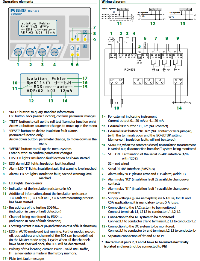
Alarm output: 3 switch contacts (SPDT), corresponding to first level alarm (K1, warning), second level alarm (K2, main alarm), equipment failure/EDS alarm (K3), supporting N/O (normally open) or N/C (normally closed) operation mode switching, factory default K1/K2 is N/O, K3 is N/C.
Alarm mode: Supports self-locking mode (manual reset after fault clearance) and non self-locking mode (automatic reset after fault clearance), which can be switched through menu settings and adapted to different fault handling processes.
Status indication: Alarm LED1 (first level alarm), Alarm LED2 (second level alarm), and equipment fault LED correspond to different alarm levels, providing intuitive feedback on the severity of the fault for quick on-site identification.
Self monitoring and testing
Self monitoring: Continuously monitor the grounding connection, line connection, and internal circuit status of the equipment itself. In case of abnormalities, trigger the K3 relay action and light up the equipment fault LED to avoid missed reports due to equipment failure.
Testing function: Supports internal/external testing buttons (N/O contacts), long press the TEST button to activate self-test, verify whether the alarm circuit, display system, and connection to the system/ground are normal, and ensure reliable device functionality.
Reset function: Internal/external reset button (N/C contact or jumper), short press the RESET button to clear the alarm memory. When the terminal is open and ISO-SETUP is set to Memory: off, insulation faults are not stored.
(2) Ground fault location function
System expansion configuration
Core components: IRDH575 host+EDS460 (main circuit positioning device)/EDS461 (control circuit positioning device)+dedicated current transformer (W series adapted to main circuit, 8000 series adapted to control circuit), optional EDS3090/EDS3091 portable positioning system.
Scalability: Supports up to 90 EDS4 series devices for interconnection, with each EDS device capable of monitoring 12 circuits, covering a total of 1080 circuits, and adapting to the fault location needs of large industrial distribution systems.
Positioning workflow
Trigger method: After IRDH575 detects an insulation fault, it automatically starts the positioning process, or can be manually started through the menu, flexibly adapting to different on-site requirements.
Signal generation: IRDH575 generates pulse positioning current, the amplitude of which depends on the system voltage and the degree of insulation fault. In case of low resistance fault, the positioning current is automatically limited, and the current limit value can be set through the menu (maximum 50mA). The pulse period is 2s and the interval is 4s to avoid affecting the normal operation of the system.
Fault identification: The positioning current pulse starts from the host through live parts, travels along the shortest path to the fault point, and then returns to the host through the insulation fault point and PE line. The current transformer on the fault path collects the pulse signal, which is evaluated by EDS equipment.
The results show that when the positioning current exceeds the response value of the EDS device, the EDS local alarm LED lights up, indicating the faulty sub circuit. At the same time, the IRDH575 LCD synchronously displays the bus address, monitoring channel, and positioning current intensity (mA/µ A) of the faulty EDS device, achieving accurate fault positioning.
Portable troubleshooting: Optional EDS3090/EDS3091 portable positioning system can track pulse signals to the source of faults, suitable for complex wiring and concealed fault troubleshooting scenarios.
PLC control circuit adaptation
Due to the sensitivity of PLC input signals, EDS461 equipment is required for control circuit positioning, and the positioning current of IRDH575 should be set to a maximum of 2.5mA or 1mA to avoid interfering with the normal operation of the PLC.
(3) Data storage and communication functions
Data recording and querying
Storage capacity: Non volatile memory can store 99 alarm messages with date and timestamp, including fault type, insulation resistance value, occurrence time, EDS device address, etc. Data will not be lost after power failure, making it easy to trace and analyze faults.
Information query: Pressing the INFO key can quickly query system leakage capacitance, device parameter settings, alarm history, and other information without entering deep menus, making operation convenient.
communication interface
RS-485 interface (BMS protocol): Supports bidirectional data communication between devices, with a maximum cable length of 1200m. It is recommended to use shielded cable J-Y (ST) Y 2 × 0.6mm ² (single ended PE for shielding layer), equipped with a 120 Ω terminal resistor (controlled by micro switch S1 to enable/disable), to reduce signal attenuation and electromagnetic interference.
Protocol extension: Can connect to Bendel protocol converters, adapt to industrial protocols such as Ethernet, MODBUS, PROFIBUS, etc., and achieve interconnection with upper control systems such as PLC and DCS.
Analog output: 0/4... 20mA optional, load ≤ 500 Ω, can convert insulation resistance signal into standard analog quantity, connect to external instruments or centralized monitoring system, achieve remote real-time monitoring of insulation status.
(4) Operation and display functions
display system
Backlit LCD screen: 4 × 16 character pure text display, character height 5mm, clear display, supports multilingual switching, real-time display of insulation resistance value (k Ω), system status, alarm information, EDS equipment status, etc.
Auxiliary display: "s" indicates that a new measurement is in progress, "+" indicates a fault on the L+side, and "-" indicates a fault on the L - side; EDS mode display (AUTO/ON/OFF/pos/1 cycle), POS mode can preset EDS address and channel (host mode only), EDS will automatically stop after detecting all channels in 1 cycle mode; Position current polarity indication (Point=active BMS communication, H=new historical record).
Operation buttons
Function keys: INFO (information query), MENU (menu call), ESC (return/confirm parameter modification), TEST (self-test), RESET (alarm reset).
Navigation keys: up/down arrow keys (menu scrolling, parameter adjustment), Enter key (confirm parameter modification).
Operation logic: Clear menu hierarchy, intuitive parameter settings, password protection support to prevent unauthorized personnel from tampering with settings.
Detailed technical parameters
(1) Electrical parameters
Category specific specifications
Monitoring system voltage low voltage type (B1 series): AC 20... 575V (3 (N) AC/single-phase, 50... 460Hz), DC 20... 575V
High voltage type (B2 series): AC 340... 760V (3 (N) AC/single-phase, 50... 460Hz), DC 340... 575V
Supply voltage AC 88... 264V (50... 460Hz), DC 77... 286V; UL/CSA applications mandate the use of 5A fuses, while 6A fuses are recommended for other scenarios; Two fuses are required for IT system power supply
Allow external DC voltage B1 series ≤ 810V, B2 series ≤ 1060V
Allow system leakage capacitance ≤ 150 (500) µ F
Relay parameters: rated contact voltage AC 250V/DC 300V, connection capacity AC/DC 5A, breaking capacity 2 A(AC 230V,cosφ=0.4)、0.2A(DC 220V,L/R=0.04s), Electrical lifespan of 12000 cycles, contact current (DC 24V) ≥ 2mA (50mW), contact level IIB (DIN IEC 60255-23)
Analog output 0/4... 20mA, load ≤ 500 Ω
Power consumption ≤ 14 VA
(2) Environmental and mechanical parameters
Category specific specifications
Working environment temperature -10 ℃...+55 ℃ (cannot operate continuously in 50mA positioning mode); The short-term working temperature can reach -25 ℃...+70 ℃
Storage environment temperature -40 ℃...+85 ℃
Climate grade DIN IEC 60721-3-3 (3K5)
Impact resistance performance during operation: 15g/11ms (IEC 60068-2-27); During transportation: 40g/6ms (IEC 60068-2-29); Option-W model: 30g/11ms
Vibration resistance performance during operation: 1g/10... 150Hz (IEC 60068-2-6); During transportation: 2g/10... 150Hz (IEC 60068-2-6); Option-W model: 1.6mm/10... 25Hz, 4g/25... 150Hz
Protection level: Internal components IP30, terminals IP20, door mounted IP40, optional IP42 (equipped with panel seals)
Installation method: Panel installation, hole size 138 × 90mm, installation direction is display facing outward, installation distance ≥ 30mm; optional DIN rail adapter (Art. No. B98060010)
Wire terminal screw terminal, supporting rigid conductors 0.2... 4mm ², flexible conductors 0.2... 2.5mm ², flexible conductors with/without plastic collars 0.25... 2.5mm ², compatible with AWG 24... 12 specification conductors
Shell and weight halogen-free flame-retardant shell, weight ≤ 900g
System installation and typical configuration
(1) Installation points
Power supply configuration: The power supply circuit is connected in series with corresponding specifications of fuses (5A for UL/CSA, 6A for others). The IT system power supply must be equipped with two fuses to ensure equipment overcurrent protection.
Grounding requirements: The equipment grounding terminal (KE) should be reliably grounded, and the RS-485 cable shielding layer should be single ended with PE to reduce electromagnetic interference; Terminal pairs 2, 3, and 4 require electrical isolation wiring and must not be connected to PE.
Wiring specifications: Measurement circuits and power cables should be laid separately to avoid cross interference; The wiring between EDS equipment and current transformers must follow polarity requirements to ensure accurate signal acquisition.
Environmental requirements: The installation location should be well ventilated, away from heat sources and strong electromagnetic interference sources, and meet the working temperature (-10...+55 ℃) and protection level requirements; The Option-W model has stronger shock and vibration resistance and is suitable for harsh environments.
(2) Typical application configuration
1. Main circuit monitoring and positioning system (AC/DC 20... 575V)
Configuration components: IRDH575B1-435+EDS460+W series current transformer+6A fuse.
Applicable scenarios: Factory three-phase main distribution circuit, motor control circuit, etc. Each EDS460 monitors 12 main circuit branches and supports cascading expansion of multiple EDS460.
Wiring method: The L1/L2/L3 terminals of the 3AC system are respectively connected to the L1/L2/L3 terminals of the equipment, the N line is connected as needed, and the KE terminal of the equipment is connected to PE; EDS460 communicates with IRDH575 through the AB terminal, and the current transformer is installed on the main circuit branch line.
2. Control circuit monitoring and positioning system (AC 20... 265V/DC 20... 308V)
Configuration components: IRDH575B1-435+EDS461+8000 series current transformer+6A fuse+PLC.
Applicable scenarios: PLC control circuits, DC instrument circuits, and other sensitive load circuits. EDS461 is designed to meet the high sensitivity requirements of control circuits and avoid interference from positioning currents on loads.
Wiring method: The L+terminal of the DC system is connected to the L1 terminal of the device, the L - terminal is connected to the L2/L3 terminal, and the KE terminal of the device is connected to the PE terminal. EDS461 communicates with IRDH575, and the current transformer is installed on the PLC input and output circuit line, with a positioning current set to 1... 2.5mA.
- YOKOGAWA
- Reliance
- ADVANCED
- SEW
- ProSoft
- WATLOW
- Kongsberg
- FANUC
- VSD
- DCS
- PLC
- man-machine
- Covid-19
- Energy and Gender
- Energy Access
- Renewable Integration
- Energy Subsidies
- Energy and Water
- Net zero emission
- Energy Security
- Critical Minerals
- A-B
- petroleum
- Mine scale
- Sewage treatment
- cement
- architecture
- Industrial information
- New energy
- Automobile market
- electricity
- Construction site
- HIMA
- ABB
- Rockwell
- Schneider Modicon
- Siemens
- xYCOM
- Yaskawa
- Woodward
- BOSCH Rexroth
- MOOG
- General Electric
- American NI
- Rolls-Royce
- CTI
- Honeywell
- EMERSON
- MAN
- GE
- TRICONEX
- Control Wave
- ALSTOM
- AMAT
- STUDER
- KONGSBERG
- MOTOROLA
- DANAHER MOTION
- Bentley
- Galil
- EATON
- MOLEX
- Triconex
- DEIF
- B&W
- ZYGO
- Aerotech
- DANFOSS
- KOLLMORGEN
- Beijer
- Endress+Hauser
- schneider
- Foxboro
- KB
- REXROTH
- YAMAHA
- Johnson
- Westinghouse
- WAGO
- TOSHIBA
- TEKTRONIX
- BENDER
- BMCM
- SMC
- HITACHI
- HIRSCHMANN
- XP POWER
- Baldor
- Meggitt
- SHINKAWA
- Other Brands
- UniOP
- KUKA
- IBA
- Beckhoff
-
LTI SC52.0040.0012.0000.0 - Servo Drive
-
Lti SC52.0040.0012.0000.0 - Servo Drive
-
Milton Industries LTI Tool By Milton LT1240 - 1/2" Drive Lugnut Remover
-
LTi Drives SO84.200.P030.0000.0-W - Servo Spindle Drive
-
LTI DRIVES LSP08-035-320-30-B0R1PY170 - Servo Motor
-
LTI DRIVES SE84.200.SC00.0001.0-W - Servo Drive
-
Lust CDE34.005.W2.2 - Lti Drives Controller
-
LTi SO84.012.0030.0011.2 - ServoOne Servo Drive
-
LTi Drives SO CM-P.0010.11.00.0 - Servo Drive Controller
-
LTi CDE34.017.W3.0 - Servo Drive
-
LTI Drives CDB32.004, C2.0,SH - Positioning Controller
-
LUST CM-CAN1 - LTi DRIVES Communication Module
-
LTi SO84.012.1030.0000.2 - Servo Drive
-
LTI MOOG CDE54.044 - PITCHMASTER FREQUENCY CONVERTER 181-01019
-
MOOG LTI 181-01019 CDE54.044 - PITCHMASTER FREQUENCY CONVERTER
-
Lust LTi Drives CDE34.010,D2.0 - Servo Drive Controller
-
LTI SO84.032.0003.0101.2 - Servo Drive
-
Seagate 9CC132-302 Harris LTI-CS IRT-34-0021-01 - Hard Drive 160GB
-
LTI SO84.032.0003.0001.2 - Servo Drive
-
LTI SO24.007.0070.0000.1 - SERVO CONTROLLER
-
LTi drive CDA32.003.C3.0.H05-01.PC1 - Servo Drive
-
LTI SO84.016.0030.0000.2 - SERVO CONTROLLER
-
LUST LTI CD A34.008,W1.4, BR - SERVO DRIVE
-
MOOG LTI 181-01019 CDE54.044 - PITCHMASTER FREQUENCY CONVERTER
-
LTI MOOG 181-01019 - PITCH Master Servo Drive CDE54.044
-
LTI SERVO ONE SO84.045.0030.0001.2-W - Drive
-
LUST LTi SO84.032.0040.0000.2 - SERVO ONE DRIVE
-
LTi Drives LSH-074-2-30-3 20/T1,G6.1M - SERVO MOTOR
-
LTI SO84.016.0000.0101.2 - servo drive
-
LTI SA54.0550.0033.0000.0 - Servo Drive
-
LTI SA54.0550.0033.0000.0 - Servo Drive
-
LTI LT 4850 - 3/8" Drive 3-Pc Twist Socket Transmission Drain Plug Removal System
-
LTI Tools LT4400-30 Lock Technology - 3/4" Twist Socket 1/2" Drive Lugnut Remover
-
LTI Tools LT-1400C - 1/2 Drive Wheel Torque Extension Tool
-
LTI Tools LT1250 - 1/2" Drive Dual Sided Socket Lug Nut Remover Tool
-
LTI SO84.032.0003.0101.2 - Servo Drive
-
LTI MOOG 181-01019 - PITCH Master Servo Drive CDE54.044
-
MOOG LTI 181-01019 CDE54.044 - PITCHMASTER FREQUENCY CONVERTER
-
MOOG LTI 181-01019 CDE54.044 - PITCHMASTER FREQUENCY CONVERTER
-
MOOG LTI 181-01019 CDE54.044 - PITCHMASTER FREQUENCY CONVERTER
-
LTI SA54.0550.0033.0000.0 - Servo Drive
-
LTI Tools LT-4800 - 7 Piece Twist Socket 3/8" Drive Oil Drain Plug Removal Set
-
LTI SA54.0550.0033.0000.0 - Servo Drive
-
LTI Drive SO24.007.00300000.0 - Servo Drive
-
LTI TOOLS LTI 1400-I - Drive Wheel Torque Extension
-
LTI Tools LT4400-3 - 3/4" 19mm Twist Socket 1/2" Drive Lugnut
-
LTI TOOLS LTI 1400-BB - Drive Wheel Torque Extension
-
LTI SO84.032.0003.0101.2 - Servo Drive
-
LTI Tools LT-4512 - 3/8" Drive 12mm Twist Socket
-
LTI MOTION Luster SO84.032.0003.0001.2 - Servo Drive
-
LTI Tool By Milton LT1600P - 1" Drive Torx Stick
-
LTI Lust VF1424L,HF,OP2,S56 - Variable Frequency Drive
-
LUST CDA32.004,C1.4,H08,B0 - SERVO DFRIVE CM-CAN1 Module
-
LTI SO84.045.0002.0001.2-W - Drive
-
LTI Lust VF1404M,C9,PT1,BR1 - Inverter Type VF1404M
-
LTI SA54.0550.0033.0000.0 - Servo Drive
-
LTI Tools LT-1400C - 1/2" Drive Wheel Torque Extension
-
Lust LTI DRiVES CDA32.006, C3.0, H09 - Variateur De Fr茅quence Frequency Inverter
-
LTI MOOG CDE54.044 - PITCH master SERVO DRIVE
-
LTI MOOG CDE54.044 - PITCH master SERVO DRIVE
-
LTI SO84.143.0020.0101.2-W - servo drive
-
LTI MOTION SC34.0200.0011.0000.0 - Servo drives
-
LTI SO84.032.0003.0001.2 - Servo Drive
-
LTI DRIVES GmbH MS100 - Assembly Set Mounting Kit
-
LTI SO84.032.0003.0001.2 - Servo Drive
-
LTI SO84.032.0003.0001.2 - Servo Drive
-
LTI MOTION SO84.032.0003.0101.2 - servo drive
-
LTI SO84.032.0003.0101.2 - Servo Drive
-
LTI MOOG CDE54.044 - PITCH master SERVO DRIVE
-
LTI MOTION CDE32.004.C2.4 - Servo drives
-
LTI CDD34.032锛學x.x锛孊R锛孭C1 - Servo Drive
-
Lust LTI DRiVES CDA32.006, C3.0, H09 - Inversor De Frecuencia Frequency Inverter
-
Lust SO84.008.0030.1000.0 - Servo One LTi Drive
-
LTI MOTION SO84.032.0003.0101.2 - Servo drives
-
LUST LTi CDA32.004,C1.4 - SERVO DRIVE
-
LTI MOOG CDE54.044 - PITCH Master SERVO DRIVE
-
LTI KEBA CDB32.004 C2.7, SH - PN: 08673530 Frequency Inverter
-
LTI Tools LT-1400C - 1/2" Drive Wheel Torque Extension
-
LTI LT1400-E - 1/2" Drive Wheel Torque Extension
-
LTI MOOG 181-01019 - PITCH master SERVO DRIVE CDE54.044
-
LTI LSN-097-0510-30-560/T1 - Actuator Motor
-
LTI Tools LT 4800 - 7 Piece 3/8" Drive Twist Socket Oil Drain Plug Removal System
-
LTI DRIVES GmbH MS100 - MONTAGESET Assembly Set Mounting Kit
-
Lti SC52.0040.0012.0000.0 - Servo Drive
-
LTI DRIVES GmbH MS100 - Juego De Montaje Assembly Set Mounting Kit
-
LTi DSM4-14.2-21R83-200 - Drives servomoteur Servo Motor
-
MOOG CDE 54.044.GDA - Pitch Master Industrielle Turbine Lti Drive
-
LTI SO24.004.0030.1000.0 - Servo Drive Controller
-
Lti MOOG CDE54.044 - Pitch Master Servo Drive
-
Lust LTI DRiVES CDA32.006, C3.0, H09 - Inverter
-
LTI MOTION GMBH CDB34.006,W3.0,PC1,H39 - Frequency inverter
-
LTI SO84.032.0003.0001.2 - Servo Drive
-
MOOG CDE 54.044.D - Pitch Master Industrielle Turbine Lti Drive
-
LTI TOOLS LT-1460 - 1/2" DRIVE WHEEL TORQUE EXTENSION KIT 5 PIECE SET
-
Lust Cdb32.003, C2.4 - Lti Drives Servoregulador Frecuencia Servo Controller Inverter
-
Lust LTI DRIVES CDA32.006, C3.0, H09 - Frequency Inverter
-
Lust Lti SO82.004.0030.0000.2 - Servo Drive
-
LTI MOTION SC34.0200.0011.0000.0-SL - Servo drives
-
LTI MOTION SA54.0075.0033.0000.0 - Servo drives
-
LTI MOTION SC32.0075.1011.0000.0 - Servo drives
-
LTI Servo-One Junior SO22.006.0080.1000.0 - Servo Controller Servoregler
-
LUST CDA32.004, C1.4, H08, B0 - Servo Drive & LTI CM-CAN1 Module
-
LTI DRIVES LSP08-035-320-30-B0R1PY170 - Servo Motor
-
LUST LTI CDA32.004,C1.4.H08.B0 - SERVO CONTROLLER DRIVES
-
LUST LTi DRiVES CDS44.072LC1.2 - Servo Drive
-
Lti Servo-One Junior SO22.006.0082.1000.0 - Servo Controller Servoregler
-
LUST CDA32.008,C2.0,HF - Lti DRIVES Spindle Drive Inverter
-
LTI SO22.003.0082.0000.0 - Servo Drives One junior Servo Controller Servoregler
-
Lust Lti Drives CM-CAN1 - Communication Module
-
LUST Lti Drives Vf1202s, G8, I6 - Frequency Inverter Drive
-
LTI DRIVES BR-090.03.540.UR.H38 - Bremswiderstand Brake Resistor
-
LTi DRIVES PM-E40.2DRA054P - Wind Turbine Pitch Control Inverter
-
LTi Drives GmbH br-110.01.540-UR - Brake Resistor
-
LTI Drives LSN-097-0960-30-0560/T1,S4,B - Servo Motor
-
LUST CDA34.006.C2.0 - LTI Drives Servoregler
-
LUST LTI DRIVES SERVO ONE JUNIOR SO24.002.0020.0000.1 - Servo Drive Controller
-
LTI MOTION SO84.032.0003.0001.2 - Servo drives
-
LTI DDTD750V2-120 - IBOP ACTUATOR CYLINDER FOR TOP DRIVE
-
LTI CDE32.004, C2.4 - SERVO DRIVE
-
LUST LTI DRIVES CDD34.017 W3.4PC1 - Servo Drive Controller
-
LTI CDA3208,C3,0,HF - AC SERVO DRIVE
-
LUST LTI DRIVES LSH-074-3-30-560/T1,G6.1S - SERVO MOTOR
-
LUST Lti CDB32.004.C2.4.SH - AC Servo Drive
-
LTi CDA32.006, C3.0, H09 - Servo Drive
-
LTI SO22.003.0010.0000.0 - Servo Drive Servo one junior Servoregler Controller
-
LTi Drives DSM4-14.2-21R83-200 - Servo Motor
-
LUST Lti Drives Lsh-097-1-30-560/T1, 1R - Servomotor
-
LTI 1237 - 7 Piece 1/2" Drive Flip Socket Set

K-JIANG

Add: Jimei North Road, Jimei District, Xiamen, Fujian, China
Tell:+86-15305925923