
K-WANG


BENDER WR70x175S (P)... WR200x500S (P) rectangular measuring current transformer
BENDER WR70x175S (P)... WR200x500S (P) rectangular measuring current transformer
Product Overview
(1) Product positioning and core applications
WR70x175S (P)... WR200x500S (P) is an industrial grade rectangular measuring current transformer developed by BENDER in Germany. It is designed for current signal conversion and precise acquisition, and is used in conjunction with residual current monitoring systems and insulation fault location systems to achieve current monitoring and fault tracing in industrial electrical circuits. It is suitable for AC/DC hybrid power supply scenarios and can convert high or positioning currents on the primary side into assessable standard signals on the secondary side, providing accurate data support for backend monitoring equipment. It is widely used in industrial scenarios such as factory distribution systems, busbar systems, IT systems (ungrounded systems), etc.
(2) Core Features and Compliance Standards
1. Core Features
Dual scenario adaptation: compatible with RCM/RCMS series residual current monitoring systems, converting AC current signals; It can also be paired with EDS series insulation fault location system (IT system) to collect the positioning current generated by PGH positioning current injector or IRDH series insulation monitoring instrument.
Series differentiation design: divided into the S series without integrated shielding and the SP series with integrated shielding. The SP series is designed specifically for busbar systems with load currents ≥ 500A, which can avoid false triggering of backend devices caused by high load currents or surge currents.
High reliability: Equipped with a built-in secondary side overvoltage protection diode, it has strong resistance to impact and vibration, and is suitable for harsh industrial environments.
Flexible installation: Supports installation in any direction, adapts wires to multiple specifications, and meets different on-site wiring needs.
2. Compliance and Certification
Following standards: DIN EN 60044-1 (General Technical Standard for Current Transformers), IEC 61869 (Power Transformer Standard), IEC 61869-2 (Insulation Coordination Standard), DIN IEC 60721-3-3 (Climate Rating Standard).
Safety level: The flame retardant rating of the shell reaches UL94 V-0, the internal component protection level is IP40, and the terminal protection level is IP20, effectively preventing solid foreign objects from entering and electrical safety risks.
Product classification and core parameters
(1) Product series and model differentiation
Series Core Features Applicable Scenarios Model Range
S series without integrated shielding, basic design for conventional industrial scenarios, circuits with load current<500A WR70x175S、WR115x305S、WR150x350S、WR200x500S
SP series with integrated shielding, strong anti-interference ability, busbar system, circuit with load current ≥ 500A, high interference environment WR70x175SP, WR115x305SP, WR150x350SP, WR200x500SP
(2) Key electrical parameters
Category specific specification remarks
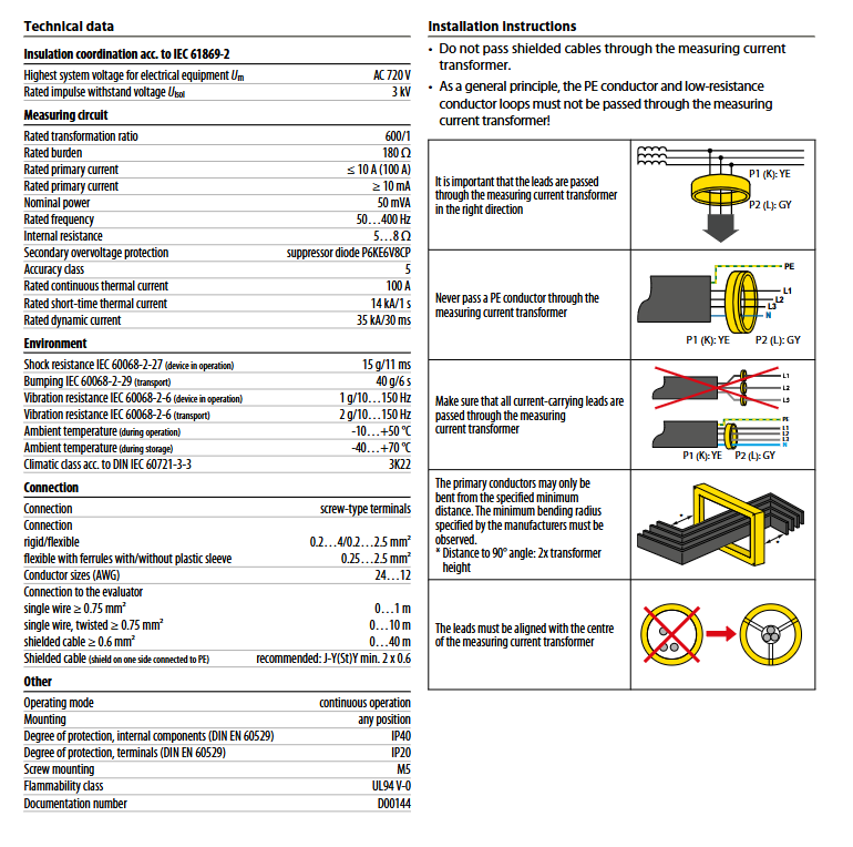
Maximum system voltage (Um) AC 720 V suitable for medium and high voltage industrial distribution systems
Rated impulse withstand voltage (Uisol) 3 kV meets industrial insulation coordination requirements
Rated transformation ratio 600:1 Fixed transformation ratio to ensure signal conversion consistency
Rated load 180 Ω matching backend monitoring/positioning equipment input impedance
Rated primary current minimum ≥ 10 mA, maximum ≤ 10 A (100 A) to cover small signal acquisition and high current monitoring requirements
Rated nominal power of 50 mVA ensures sufficient signal transmission power
Rated frequency 50... 400 Hz, suitable for industrial scenarios of power frequency and intermediate frequency
Internal resistance of 5... 8 Ω reduces signal transmission loss
Secondary side overvoltage protection suppression diode P6KE6V8CP prevents overvoltage damage to backend equipment
Accuracy level 5 meets the requirements of industrial current measurement error
Rated continuous thermal current of 100 A, stable long-term operation without overheating risk
Rated short-time thermoelectric current 14 kA/1 s withstand short-time short-circuit current surge
Rated dynamic current of 35 kA/30 ms to resist instantaneous dynamic current surge
(3) Physical dimensions and weight
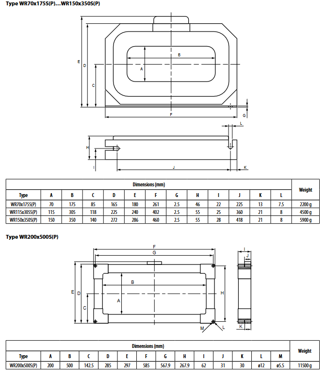
1. Size and weight of WR70x175S (P)~WR150x350S (P)
Model size (mm) Weight
A (internal width) B (internal height) C D E F G H I J K L
WR70x175S(P) 70 175 85 165 180 261 2.5 46 22 225 13 7.5 2200 g
WR115x305S(P) 115 305 118 225 240 402 2.5 55 25 360 21 8 4500 g
WR150x350S(P) 150 350 140 272 286 460 2.5 55 28 418 21 8 5900 g
2. WR200x500S (P) size and weight
Model size (mm) Weight
A (internal width) B (internal height) C D E F G H I J K L M
WR200x500S(P) 200 500 142.5 285 297 585 567.9 267.9 62 31 30 ø12 ø5.5 11500 g
Installation and wiring specifications
(1) Core installation requirements
Prohibited conductors to pass through:
It is strictly prohibited to pass shielded cables, PE conductors, and low resistance conductor circuits through transformers, otherwise interference signals may be introduced, leading to a decrease in measurement accuracy or misjudgment by backend equipment.
All current carrying wires must pass through the transformer completely without omission, ensuring comprehensive collection of current signals.
Wire threading direction and position:
The wire needs to be threaded in from the P1 (K end, yellow mark) side and out from the P2 (L end, gray mark) side. Incorrect direction can cause signal polarity reversal and affect data accuracy.
The wires need to be aligned with the center position of the transformer to avoid uneven magnetic field distribution caused by offset, further ensuring measurement accuracy.
Wire bending and spacing:
The bending of the primary side conductor must follow the minimum bending radius specified by the manufacturer, and the 90 ° bending distance must not be less than twice the height of the transformer to prevent insulation damage to the conductor and distortion of current distribution.
Installation and fixation:
Supports installation in any direction (horizontal, vertical, etc.), fixed on the installation surface with M5 screws to ensure a firm and secure installation without looseness, and to avoid vibration affecting performance during operation.
(2) Wiring and Connection Specifications
Conductor adaptation:
The terminal block is screw type and supports rigid conductors (0.2... 4mm ²), flexible conductors (0.2... 2.5mm ²), and flexible conductors with/without plastic collars (0.25... 2.5mm ²), compatible with AWG 24... 12 specification conductors.
Cable selection and distance:
Single core wire (≥ 0.75mm ²): maximum connection distance of 1m.
Twisted single core wire (≥ 0.75mm ²): maximum connection distance of 10m.
Shielded cable (≥ 0.6mm ²): maximum connection distance of 40m, recommended model J-Y (St) Y 2 × 0.6mm ², shielding layer needs to be connected to PE at one end to reduce electromagnetic interference.
Wiring precautions:
Before wiring, the power supply must be disconnected to ensure construction safety; Tighten the terminal screws after wiring to avoid signal distortion caused by poor contact.
Connected to backend devices (RCM/RCMS/EDS) through two-wire cables, S1 (k) and S2 (l) terminals correspond to device signal input interfaces.
Environmental adaptability and mechanical characteristics
(1) Environmental parameters
Category specific specifications
Working environment temperature -10 ℃...+50 ℃
Storage environment temperature -40 ℃...+70 ℃
Climate grade DIN IEC 60721-3-3 (3K22)
Impact resistance performance (in operation) 15 g/11 ms (IEC 60068-2-27)
Anti collision performance (during transportation) 40 g/6 ms (IEC 60068-2-29)
Vibration resistance performance (in operation) 1 g/10... 150 Hz (IEC 60068-2-6)
Vibration resistance performance (during transportation) 2 g/10... 150 Hz (IEC 60068-2-6)
(2) Mechanical characteristics
Shell material: flame retardant grade UL94 V-0, high temperature resistance, anti-aging, in line with industrial safety requirements.
Protection level: Internal components IP40 (preventing solid foreign objects with a diameter of ≥ 1mm from entering), terminals IP20 (preventing finger touch).
Operation mode: Continuous operation, uninterrupted collection of current signals, meeting the 24-hour uninterrupted production needs of industry.
Model specifications and ordering information
(1) Model and Order Number Correspondence Table
Model Internal dimensions (mm) Shielding characteristics Order number
WR70x175S 70 × 175 without B911738
WR115x305S 115 × 305 without B911739
WR150x350S 150 × 350 without B911740
WR200x500S 200 × 500 without B911763
WR70x175SP 70 × 175 integrated shielding B911790
WR115x305SP 115 × 305 integrated shielding B911791
WR150x350SP 150 × 350 integrated shielding B911792
WR200x500SP 200 × 500 integrated shielding B911793
(2) Selection suggestions
Selection based on load current: If the load current is ≥ 500A or applied to the busbar system, the SP series (with shielding) is preferred; For conventional load current scenarios, select the S series.
Select according to internal dimensions: Select the corresponding internal dimensions based on the number and thickness of the primary side conductors to ensure that the conductors can pass through the transformer smoothly and leave appropriate gaps.
Selection based on connection distance: When the connection distance exceeds 10m, shielded cables should be selected and matched with the wiring requirements of the corresponding transformer model.
Precautions and Maintenance Guidelines
(1) Precautions for use
It is strictly prohibited to dismantle the transformer casing or modify the internal circuit without authorization, otherwise it will damage the insulation performance and shielding structure, and lose the product warranty qualification.
Transformers need to be used in conjunction with compatible backend devices (RCM/RCMS/EDS) to avoid signal attenuation or equipment damage caused by load mismatch.
Installation and maintenance must be carried out by qualified electrical professionals, strictly following local electrical safety regulations.
(2) Key points of daily maintenance
Regular inspection: Check the installation and fixation of the transformer, whether the wiring terminals are loose, and whether the cable insulation layer is damaged every month. If any problems are found, they should be dealt with in a timely manner.
Environmental cleaning: Keep the surface of the transformer clean to avoid dust accumulation affecting heat dissipation or insulation performance.
Fault handling: If there is no signal input or signal abnormality in the backend equipment, it is necessary to sequentially check whether the cable connection, conductor direction, and transformer are damaged. If necessary, contact the manufacturer's technical support.
- YOKOGAWA
- Reliance
- ADVANCED
- SEW
- ProSoft
- WATLOW
- Kongsberg
- FANUC
- VSD
- DCS
- PLC
- man-machine
- Covid-19
- Energy and Gender
- Energy Access
- Renewable Integration
- Energy Subsidies
- Energy and Water
- Net zero emission
- Energy Security
- Critical Minerals
- A-B
- petroleum
- Mine scale
- Sewage treatment
- cement
- architecture
- Industrial information
- New energy
- Automobile market
- electricity
- Construction site
- HIMA
- ABB
- Rockwell
- Schneider Modicon
- Siemens
- xYCOM
- Yaskawa
- Woodward
- BOSCH Rexroth
- MOOG
- General Electric
- American NI
- Rolls-Royce
- CTI
- Honeywell
- EMERSON
- MAN
- GE
- TRICONEX
- Control Wave
- ALSTOM
- AMAT
- STUDER
- KONGSBERG
- MOTOROLA
- DANAHER MOTION
- Bentley
- Galil
- EATON
- MOLEX
- Triconex
- DEIF
- B&W
- ZYGO
- Aerotech
- DANFOSS
- KOLLMORGEN
- Beijer
- Endress+Hauser
- schneider
- Foxboro
- KB
- REXROTH
- YAMAHA
- Johnson
- Westinghouse
- WAGO
- TOSHIBA
- TEKTRONIX
- BENDER
- BMCM
- SMC
- HITACHI
- HIRSCHMANN
- XP POWER
- Baldor
- Meggitt
- SHINKAWA
- Other Brands
- UniOP
- KUKA
- IBA
- Beckhoff
-
Basler Electric DECS-250-CN1SN1N Automatic Voltage Regulator for Generator Excitation Control
-
ADLINK CPCI-6860A - 51-31310-OB10 industrial motherboard CompactPCI SBC
-
ADLINK AmITX-SL-G-H110 - 51-7A104-0A30 Mini-ITX Industrial Motherboard
-
ADLINK PXI-2005-003 - CPCI Industrial PC Data Acquisition Card Multi-Function DAQ
-
ADLINK DININ-814M - 51-14032-0A3D SCSI-100P cable connection Interface Terminal Board
-
ADLINK CPCI-3920NA/C2D15/M1G - 3U CompactPCI Intel Core 2 Duo Single Board Computer
-
ADLINK PCIE-8560 - 51-18014-0A20 Communication Card High Speed DAQ
-
ADLINK PCI-C154+ - Motion Control Card 4-axis Motion Controller Board
-
ADLINK PCI-RTV24 - image capture card Analog Video Frame Grabber
-
ADLINK NuPRO-842LV/P - 51-41360-0B30 Industrial Motherboard CPU Board
-
ADLINK cBP-3208/3208R - CPCI Board 3U 8-Slot CompactPCI Backplane
-
ADLINK PCI-8164 - 4-Axis Motion Controller PCI Card 51-12406-0A40
-
ADLINK PCIe-GIE64+ - 4-CH GigE Vision PoE+ Frame Grabber Video Capture Card
-
ADLINK CPCI-6860 / 6860A - CompactPCI Dual Xeon Single Board Computer
-
ADLINK IEC-915GV - REV 1.1 Industrial motherboard CPU Board
-
ADLINK ND-6520 - Technology RS-232 to RS-422RS-485 Converter NuDAM Module
-
ADLINK RTV-24 / PCI-MP4S - 51-12519-1C30 4-Channel Real Time Video Capture Board
-
ADLINK cPCI-6910 / cPCI-6910AM/M1G - cPCI-6910AM/DXL16/M1G/S80G(G)-3120 BOARD CompactPCI SBC
-
ADLINK NUPRO-A40H - Linghua 51-41807-1A30 Industrial Control Computer Motherboard
-
ADLINK USB-3488A - USB to GPIB INTERFACE USB-3488A(G) Controller Module
-
ADLINK PCI-8134A - motion control card 4-Axis Controller Card
-
ADLINK PCI-7432 - Board 32-Channel input / 32-output Isolated Digital I/O PCI Card
-
ADLINK PCI-8134A - 51-12421-0A10 motion controller card tested
-
ADLINK LPCIe-7230 - 32 CH Isolated Input/output Card 2 Interrupts Low Profile PCIe
-
ADLINK NuPRO-E340 - industrial computer motherboard 51-47807-0A30 PICMG 1.3 SHB
-
ADLINK PCI-7434 - High-speed Digital Acquisition Card 64-CH Isolated DO Card
-
ADLINK NuPRO-E330 - 51-41805-0A20 Indsutrial Board SHB Single Board Computer
-
ADLINK PCI-7248 - OPTO-22 48 CHANNEL DIO DIGITAL TTL/DTL I/O 51-12006-0A40 GP
-
ADLINK PCI-8134 - Motion control card 4-Axis Controller Card
-
ADLINK AMP-208C - Movimiento Control Tarjeta 51-12420-1A20 W/Expansión & Breakout
-
ADLINK PCI-8164 - 51-12406-0A40 PCB Board 4-Axis Motion Controller Card
-
ADLINK DIN-68Y-SGII / DIN-68M-J3A - Terminal Board Connector Interface Block
-
ADLINK PCIe-7432 - Technology 51-18402-0A10 PCIe Card With High Input Range
-
ADLINK PCI-8144 / PCI-8144N - Motion control card 4-Axis Stepper Controller Card
-
ADLINK HSL-HUB3/REPEATER - HIGH SPEED LINK EXTENSION MODULES Distributed Hub Module
-
ADLINK ND-6017 - Data Logging + Acquisition 8CH A/D input Mod NuDAM Module
-
ADLINK LPCIe-7250 - data acquisition card Low Profile 8-CH Relay Output Card
-
ADLINK PCI-7432 - I/O card 64-CH Isolated Digital Input Output PCI Card
-
ADLINK IMB-M43H - industrial control computer motherboard Q87 Chip Micro-ATX
-
ADLINK MP-C154 - Motion control Card 4-Axis Motion Controller Board
-
ADLINK PCI-RTV24 - image capture card Video Frame Grabber Card
-
ADLINK PCI-7250 - 8-CH Relay Output & 8-CH Isolated DI Card
-
ADLINK PCI-6308V - 8-CH 12-Bit Isolated Analog Output PCI Card PCB-I-E-1148=6EX2
-
ADLINK PCI-7248 - capture card 48-CH Opto-22 Compatible DIO Card
-
ADLINK HSL-AI16A02-M-VV - Analog Input Output Distributed Module
-
ADLINK NuPRO-A301 - Rev:1.4 NUPRO-A301 PICMG Full-Size Single Board Computer
-
ADLINK PCI-6208V-GL - 8-CH Voltage Analog Output PCI Card
-
ADLINK PCI-8134A - 51-12421-0A10 4-Axis Motion Controller Card
-
ADLINK MNET-S23 - TECHNOLOGY MNET S23 - SERVO DRIVER CONTROL MODULE
-
ADLINK M-342 - ATX I3 I5 I7 Q67 Industrial Motherboard
-
ADLINK NUPRO-780 - Industrial Motherboard CPU Board PICMG SBC
-
ADLINK MP-C154 / MP-C152 - 4-Axis Motion Control Card Pulse-Train Controller
-
ADLINK NuPRO-935A/LV10B0 - Motherboard 51-41802-0A10 GP w/RAM Industrial Control Board
-
ADLINK MP-C154 - Motion control card 4-Axis Motion Controller Mainboard
-
ADLINK PCI-7250 - PCI Acquisition Card 8-CH Relay Output Isolated DI Card
-
ADLINK ACL-7124 - Technology Inc.24 DIO Card Digital Input Output Card
-
ADLINK PCI-8554 A2 - Timer/Counter Data Acquisition Card
-
ADLINK DIN-825-GP4 - Terminal Block Interface Board Breakout Module
-
ADLINK NuPR0-761 - REV:1.1 Industrial motherboard Full-Size PICMG SBC
-
ADLINK MXE-1401/M8G (G) - Matrix Fanless Embedded Computer Industrial PC
-
ADLINK HSL-DI16DO16-UD-NN - Digital 16 Channel I/O Mod Distributed I/O Module
-
ADLINK ND6520 - NUDAM INTELLIGENT DA&C MODULE RS232-RS-422/RS485 CONVERTOR
-
ADLINK NUPRO-761 - REV:1.1 Industrial Motherboard CPU Board
-
ADLINK AMP-208C - Motion Control Card 51-12420-1A20 DSP-based 8-axis
-
ADLINK NuPRO-A301REV 1.4 - with packaging industrial computer motherboard PICMG SBC
-
ADLINK PCM-9112+ - 51-12300-0A2 industrial motherboard Multi-Function DAQ PC/104 Module
-
ADLINK PCM-7250+ - 8-CH Relay Outputs & 8-CH Isolated DI Module PC/104
-
ADLINK PCI-RTV24 - Image capture card Analog Video Frame Grabber
-
ADLINK PCI-8134 - Motion Controller PCI Card 4-Axis Controller Board
-
ADLINK PCI-7432 - Isolated Digital I/O PCI Card
-
ADLINK PCI-8554 A2 - acquisition card Timer/Counter Card
-
ADLINK PCI-8132 - Rev.A2 2-Axis Servo & Stepper Motion Controller Card
-
ADLINK PCI-8132 - Data Acquisition card 2-Axis Motion Controller Card
-
ADLINK EBP-13E4 - 51-46703-0A30 Industrial Backplane Board Passive Backplane
-
ADLINK PCI-800L - Electronic Card Interface Controller Card
-
ADLINK PCIe-GIE72 - 51-18531-0A10 PCB Board GigE Vision Frame Grabber
-
ADLINK DAQ-2010(G)-OOBO - Simultaneous-Sampling Multi-Function DAQ Card
-
ADLINK PCI-9112 - REV.B1 Multifunction DAQ Card Data Acquisition Card
-
ADLINK PCI-7230 - 51-12003-DA60 32-CH Isolated Digital I/O Card
-
ADLINK PCI-7432 - Data Acquisition Card Isolated Digital I/O PCI Card
-
ADLINK ETX-AT-N270-18/LXE - 51-71111-0A20 ETX CPU Module Motherboard
-
ADLINK HSL-DI32-UD-N - DIGITAL INPUT 32 POINTS MODULE Distributed I/O
-
ADLINK AMP-204C - Motion Control card DSP-Based 4-Axis Advanced Controller
-
ADLINK MNET-4XMOG-0050 - Four-axis Motion Controller Distributed Motion Module
-
ADLINK AMP-204C - Motion control card DSP-Based 4-Axis Pulse-Train Controller
-
ADLINK PCI-7442 - Switch card 64-Channel Datalogging & Acquisition Card
-
ADLINK M-302 - Industrial control motherboard ATX PC Board
-
ADLINK NUPRO-852 / NUPRO-852LV - Industrial motherboard Single Board Computer
-
ADLINK PCI-8134 - REV.B1. 4-Axis Motion Controller Card
-
ADLINK PCI-GIE62 + - 51-18502-0A20 2-CH GigE Vision Frame Grabber PoE Card
-
ADLINK PCI-MPG24 - 51-12523-0B20 MPEG4 Card Video Compression Hardware
-
ADLINK HSL-TB32-M-DIN - 32-CH I/O TERMINAL W/ HSL-AI16AO2-M-VV MODULE
-
ADLINK PCI-M114-GL - PCB Ver 2.1 Motion Controller Axis Card
-
ADLINK IMB-M40H - SYM76996H61 motherboard Industrial Computer Mainboard
-
ADLINK NUPRO-A40H - 51-41807-1A20 industrial control motherboard H61 Chip
-
ADLINK PCI-M114-GL - Axis Card Data Acquisition Card PCB VER2.2 Motion Controller
-
ADLINK PCI-8134 - Motion Controller PCI Card 4-Axis Controller Board
-
ADLINK PCI-8102 - Motion control card 2-Axis Servo & Stepper Controller
-
ADLINK NuPRO-841REV:3.0 - motherboard Industrial Control PC Board
-
ADLINK HSL-TB32-U-DIN REV A1 - Breakout Terminal Board Field I/O Module
-
ADLINK AMP-204C - Motion Control card DSP-Based 4-Axis Pulse-Train Controller
-
ADLINK NUPRO-A40H - 51-41807-1A20 industrial control motherboard H61 PC Board
-
ADLINK PCI-6308A / PCI-6308V - 51-12202-0A50 Isolated Analog Output Card
-
ADLINK AMP-204C - DSP-Based 4-Axis Advanced Pulse-Train Motion Controller
-
ADLINK PCI-7434 - Technology 64-Channel Isolated Digital I/O PCI Cards
-
ADLINK CPCI-6840 / CPCI-6840V / PM16/M1G-12G0 - CompactPCI Single Board Computer CPU Module
-
ADLINK PCIE-GIE74 - Motherboard Video Capture Card 51-18531-0A10 Frame Grabber
-
ADLINK NuPRO-E330 - industrial computer equipment motherboard Control Mainboard
-
ADLINK AMP-208C / 51-12420-1A20 - Motion Control Card W/ Expansion & Breakout Board
-
ADLINK HPCI-14S12U - industrial computer baseboard Passive Backplane 14 Slots
-
ADLINK PCI-8164 - 4-Axis Motion Controller PCI Card W/ 1x Cable, 1x Breakout Box
-
ADLINK PCIe-RTV24 - 51-18016-0A20 Image Acquisition Video Capture Card
-
ADLINK M-342 - 5 PCI ATX Motherboard Industrial PC Mainboard
-
ADLINK PCI-FIW64 - 4/2 Channel IEEE1394B Image Capture Card FireWire Frame Grabber
-
ADLINK PCI-7432 - digital IO card 64-CH Isolated Digital Input Output Card
-
ADLINK 51-12001-0C20 - Circuit Board PCI-7200 Data Acquisition Controller Card
-
ADLINK PXI-3920 - PXI 3U cPCI Industrial Controller Embedded System CPU Board
-
ADLINK NuPRO-841REV:2.0 - motherboard Industrial Control PC Board
-
ADLINK NuPro-E330 - 51-41805-0A20 PCB Industrial Control Computer Motherboard
-
ADLINK PCI-RTV24 - Image capture card Analog Video Frame Grabber
-
ADLINK PCI-7442 - Switch card 64-Channel Datalogging & Acquisition Card
-
ADLINK HPX-13S4 - device baseboard Passive Backplane Riser Card
-
ADLINK PCI-9112 REV A.1 - Multi Function DA&C Board Data Acquisition Card
-
ADLINK PCI-7248 - 51-12006-0A40 Card Control 48-CH Digital I/O Module
-
ADLINK CPCI-6860 / 6860A - motherboard CompactPCI Dual Xeon Single Board Computer
-
ADLINK DPAC-3020-11(G) - Embedded PC Automation Controller Machine Control Board
-
ADLINK NuPRO-841 REV:1.0 - industrial control motherboard CPU Board
-
ADLINK MNET-4XMOG-0050 - Four-axis Motion Controller MNET Motion Control Card

K-JIANG

Add: Jimei North Road, Jimei District, Xiamen, Fujian, China
Tell:+86-15305925923