
K-WANG


ibaBM-CAN CAN / CANopen Bus Sniffer
ibaBM-CAN CAN / CANopen Bus Sniffer
Product basic information
Product positioning: ibaBM CAN is a CAN/CANopen bus sniffer developed by iba AG in Germany. Its core function is to extract CAN bus message measurement data and CAN bus diagnosis. It can seamlessly connect to existing CAN buses without changing their physical characteristics, and supports independent connection of 2 CAN buses and independent control of terminal resistance;
Version and Certification: The manual version is Issue 1.1 (January 20, 2014), and the equipment complies with European standards and CE certification, with order number 13.122000;
Core advantage: The unique microsecond level CAN bus cycle time measurement function can detect faults such as bus overload and insufficient priority of important IDs. The measurement data can be graphically displayed in ibaPDA-V6 and used to trigger control.
Core Key Characteristics
Specific parameters/functions of characteristic categories
Connect two CAN buses (Bus0/Bus1) to the CAN bus, with speeds ranging from 10kbit/s to 1Mbit/s; Supports 11 bit standard IDs (0x1~0x7ff) and 29 bit extended IDs (0x1~0x1f ff ff ff)
The data transmission capacity can transmit 512 analog signals per millisecond (supporting BYTE/INT/WORLD/DINT/DWORD/FLOAT, large/small end)+512 digital signals; Analog signals support linear conversion of Gain/Offset to physical units
Communication interface fiber optic: ibaNet 32Mbit/s TX interface (RX not functional), maximum transmission distance without relay 2000m, needs to be matched with ibaFOB-D series fiber optic input card;
Configuration: Ethernet TCP/IP (10/100Mbit/s), USB 2.0, used for parameter configuration and firmware updates
The diagnostic function measures the cycle time (μ s) of each ID message transmission and diagnoses the deterministic behavior of the diagnostic bus; Support timeout configuration, send the last value or default value when timeout occurs
Bus adaptation can be accessed as a bus terminal, intermediate node, or loop through mode; Two independent CAN bus terminal resistors (120 Ω) switch, which does not affect the original CAN bus communication
System operation requirements
The operation of the device requires both hardware and software requirements, and the core configuration is as follows:
Hardware Requirements
Power supply: 24V DC/1A power supply (actual maximum consumption of 600mA for equipment);
Configuration end: PC/laptop that can be connected to Ethernet or USB;
Measurement end: IBM compatible PC (minimum Pentium III 1GHz, 512MB RAM, 4GB hard drive, 1 idle PCI slot);
Special accessories: at least 1 ibaFOB-D series fiber input card, 1 ibaNet fiber jumper, CAN bus network;
Grounding: Optional shielded grounding connector X29, grounded according to the control cabinet configuration.
Software Requirements
Data collection/recording: ibaPDA-V6 (≥ 6.24 version) or ibaQDR-V6;
Data analysis: ibaAnalyzer;
Driver: USB configuration requires the installation of iba AG USB Remote NDK Network Device driver (provided with the device CD-ROM).
Packaging List and Default Parameters
Packing list: ibaBM CAN equipment, manual, USB cable, 2-pin power terminal, CD-ROM (including driver);
Default network/password parameters:
Ethernet TCP/IP: DHCP automatically obtains IP address;
USB TCP/IP: Fixed IP 192.168.0.1, subnet mask 255.255.255.0;
User permissions: regular user (account can, password can), administrator (account admin, password can).
Equipment Installation and Disassembly
The device is installed vertically on DIN rails, and there is no need to open the device during the entire operation process (there are no maintenance parts inside, and opening the cover will result in loss of warranty). The core steps are:
Installation steps
Press the DIN rail buckle on the back of the device, insert the device into the rail and secure it;
Grounding the device through shielded connector X29 as needed;
Connect a 24V DC power supply (pay attention to polarity), then connect the fiber optic cable (TX connected to ibaFOB-D input card) and configure the interface (Ethernet/USB) in sequence;
According to the CAN bus access mode, set the S4/S5/S6 switch (terminal resistance/direct mode).
Disassembly steps
Turn off the device power switch S11 and disconnect all external connections (power, fiber optic, configuration interface, CAN bus);
Press and hold the top of the device with one hand, and press the bottom buckle with the other hand and lift it up to detach the device from the DIN rail.
Equipment Structure and Core Components
The device consists of three parts: interfaces, control components, and indicator components. Each component has clear functions, and the core components are as follows:
Core interface (including pin definition)
Interface name identifies key parameters of core functions
CAN bus interface X40 (Bus0)/X41 (Bus1) is connected to 2 CAN bus D-Sub9 pins, Pin2=CAN_L, Pin7=CAN-H, Pin3=GND, Pin5=shielded
Fiber optic interface RX/TX data transmission to ibaPDA RX with no function, TX=32Mbit/s ibaNet, ST connector, 62.5/125 μ m fiber optic
Ethernet interface X22 TCP/IP configuration/firmware update 10/100Mbit/s, unique MAC address, device name format can_nnnn (nnnn is the last 4 bits of MAC)
USB interface X23 local configuration/firmware update USB 2.0, requires the installation of a dedicated NDK driver, fixed IP 192.168.0.1
Power interface -24V DC power supply 2-pin Phoenix terminal, 24V DC ± 10%, maximum 600mA
Shielding grounding X29 equipment grounding should be connected as needed to match the shielding grounding requirements of CAN bus cables
Control Components
Component identification type core function
The power switch of S11 ship type switchgear does not affect CAN bus communication when turned off
S1/S2 rotary switch combined with S10 to restore factory settings (S1=6, S2=9)
Press the reset button on S10 to restore factory settings in conjunction with S1/S2
S4 dip switch Bus0 terminal resistor (120 Ω) switch, ON=ON
S5 dip switch Bus1 terminal resistor (120 Ω) switch, ON=ON
S6 dip switch Bus0/Bus1 direct switch, ON=two bus connections (loop mode)
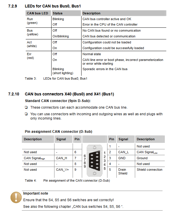
Indicator element (LED)
The device includes three types: device status LED, communication interface LED, and CAN bus LED. Each status has a clear meaning, and the core is as follows:
Device status LED: Run (green, 1Hz flashing=normal, constantly on/off=fault), 32Mb (white, on/flashing=fiber optic communication), Stop (red, on=internal fault, flashing=startup error);
Communication interface LED: Ethernet (green=connected, red=faulty), USB (green=connected, red=faulty), CF (no function, only card detection);
CAN bus LED (Bus0/Bus1): Run (green=controller normal), Bus (yellow=bus communication), Act (white=configuration loaded successfully), Err (red=bus error, flashing=occasional fault).
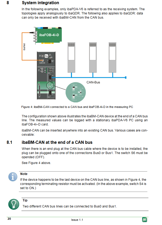
CAN bus system integration mode
IbaBM CAN supports three CAN bus access modes without modifying the original bus structure. The switch configuration corresponds to the access method:
Applicable scenarios for access mode S4/S5 settings S6 settings Key instructions
The bus terminal device connected to the CAN bus terminal plug corresponds to the bus ON (opening the terminal resistor) OFF, which can simultaneously connect to 2 independent CAN buses (Bus0/Bus1 each connected to 1)
Bus intermediate devices connected to CAN bus intermediate nodes are all turned off (terminal resistors are turned off), which does not affect the original communication of the bus and only collects data
The loop through device is connected to the CAN bus with both end plugs turned off (terminal resistance turned off) and turned on (direct connection turned on). Only one CAN bus is supported, and Bus0/Bus1 connection is a loop
Core Configuration Method
The device configuration is divided into three parts: physical switch configuration, software configuration (ibaPDA-V6), and web interface configuration, which work together to achieve full functional configuration:
Physical switch configuration
Terminal resistance: S4/S5 independently controls the 120 Ω terminal resistance of Bus0/Bus1, and the bus end needs to be turned on;
Direct mode: When S6 is turned on, Bus0/Bus1 are connected, only used for loop direct mode;
Factory reset: S1=6, S2=9, press and hold S10 and restart the device, release after 10 seconds to clear network/password configuration (signal parameters. csv retained).
ibaPDA-V6 software configuration (core, used for signal acquisition)
To be completed in ibaPDA-V6 I/O Manager, the core steps are:
Connect the device power supply, fiber optic cables, and configuration interfaces, start ibaPDA-V6, and open the I/O manager;
Select ibaFOB-D fiber optic card, add ibaBM CAN module (supporting automatic detection), configure global parameters such as bus baud rate, timeout, IP address, etc;
Add Sniffer submodule under ibaBM CAN module to configure the bus for analog/digital signals COB ID、 Data type, address, etc;
Activate the configuration and verify it, and the configuration will be automatically transferred to the non-volatile memory of the device.
Key configuration items:
Analog signal: supports 6 data types including BYTE/INT/FLOAT, can set Gain/Offset linear conversion, and can choose the final value/default value when timeout occurs;
Digital signal: Positioned by byte offset and bit number, supporting two data sources: IO data/status information;
Timeout configuration: Supports global bus timeout and individual COB ID independent timeout (microsecond level).
Web Interface Configuration (for Device Management)
The device has a built-in web server, accessed through Ethernet/USB, dual user permission management, and core functions:
Access method: Regular user (can/can) Administrator (admin/can)
Ethernet View Device Status/Diagnostic Information Configure Network/Change Password/Firmware Update/View Signal Configuration
USB View Device Status/Diagnostic Information Configure Network/Change Password/Firmware Update/View Signal Configuration
Core management functions:
Network configuration: Set Ethernet/USB IP, subnet mask, gateway, enable/disable DHCP;
Password modification: Change the passwords of regular users and administrators. Forgetting the password can restore the factory password;
Firmware update: Upload CAB format firmware file, complete device firmware upgrade (power cannot be turned off during upgrade);
Status check: View device hardware/firmware version, CAN bus status, startup logs, signal configuration.
Technical Parameters
The physical, electrical, and environmental parameters of the equipment meet the requirements of industrial scenarios, and the core parameters are shown in the following table:
Specific indicators for parameter categories
Environmental parameters Operating temperature: 0~50 ℃; Storage/transportation temperature: -25~70 ℃; Humidity: Class F (no condensation); Protection level: IP20
Electrical parameter power supply: 24V DC ± 10% (non regulated); Maximum current: 600mA; cooling method: passive heat dissipation
Physical parameter installation method: DIN rail vertical installation; Size: 69 × 189 × 148mm (including guide rail buckle); Weight: Approximately 1.3kg (including packaging/documentation)
Communication parameters fiber optic: 32Mbit/s, ST connector, 62.5/125 μ m fiber optic, no relay 2000m;
Ethernet: 10/100Mbit/s; USB:2.0; CAN bus: 10kbit/s~1Mbit/s
Mechanical characteristics comply with DIN IEC 68-2-6 standard (when firmly installed on DIN rails)
- YOKOGAWA
- Reliance
- ADVANCED
- SEW
- ProSoft
- WATLOW
- Kongsberg
- FANUC
- VSD
- DCS
- PLC
- man-machine
- Covid-19
- Energy and Gender
- Energy Access
- Renewable Integration
- Energy Subsidies
- Energy and Water
- Net zero emission
- Energy Security
- Critical Minerals
- A-B
- petroleum
- Mine scale
- Sewage treatment
- cement
- architecture
- Industrial information
- New energy
- Automobile market
- electricity
- Construction site
- HIMA
- ABB
- Rockwell
- Schneider Modicon
- Siemens
- xYCOM
- Yaskawa
- Woodward
- BOSCH Rexroth
- MOOG
- General Electric
- American NI
- Rolls-Royce
- CTI
- Honeywell
- EMERSON
- MAN
- GE
- TRICONEX
- Control Wave
- ALSTOM
- AMAT
- STUDER
- KONGSBERG
- MOTOROLA
- DANAHER MOTION
- Bentley
- Galil
- EATON
- MOLEX
- Triconex
- DEIF
- B&W
- ZYGO
- Aerotech
- DANFOSS
- KOLLMORGEN
- Beijer
- Endress+Hauser
- schneider
- Foxboro
- KB
- REXROTH
- YAMAHA
- Johnson
- Westinghouse
- WAGO
- TOSHIBA
- TEKTRONIX
- BENDER
- BMCM
- SMC
- HITACHI
- HIRSCHMANN
- XP POWER
- Baldor
- Meggitt
- SHINKAWA
- Other Brands
- UniOP
- KUKA
- IBA
- Beckhoff
-
LTI SC52.0040.0012.0000.0 - Servo Drive
-
Lti SC52.0040.0012.0000.0 - Servo Drive
-
Milton Industries LTI Tool By Milton LT1240 - 1/2" Drive Lugnut Remover
-
LTi Drives SO84.200.P030.0000.0-W - Servo Spindle Drive
-
LTI DRIVES LSP08-035-320-30-B0R1PY170 - Servo Motor
-
LTI DRIVES SE84.200.SC00.0001.0-W - Servo Drive
-
Lust CDE34.005.W2.2 - Lti Drives Controller
-
LTi SO84.012.0030.0011.2 - ServoOne Servo Drive
-
LTi Drives SO CM-P.0010.11.00.0 - Servo Drive Controller
-
LTi CDE34.017.W3.0 - Servo Drive
-
LTI Drives CDB32.004, C2.0,SH - Positioning Controller
-
LUST CM-CAN1 - LTi DRIVES Communication Module
-
LTi SO84.012.1030.0000.2 - Servo Drive
-
LTI MOOG CDE54.044 - PITCHMASTER FREQUENCY CONVERTER 181-01019
-
MOOG LTI 181-01019 CDE54.044 - PITCHMASTER FREQUENCY CONVERTER
-
Lust LTi Drives CDE34.010,D2.0 - Servo Drive Controller
-
LTI SO84.032.0003.0101.2 - Servo Drive
-
Seagate 9CC132-302 Harris LTI-CS IRT-34-0021-01 - Hard Drive 160GB
-
LTI SO84.032.0003.0001.2 - Servo Drive
-
LTI SO24.007.0070.0000.1 - SERVO CONTROLLER
-
LTi drive CDA32.003.C3.0.H05-01.PC1 - Servo Drive
-
LTI SO84.016.0030.0000.2 - SERVO CONTROLLER
-
LUST LTI CD A34.008,W1.4, BR - SERVO DRIVE
-
MOOG LTI 181-01019 CDE54.044 - PITCHMASTER FREQUENCY CONVERTER
-
LTI MOOG 181-01019 - PITCH Master Servo Drive CDE54.044
-
LTI SERVO ONE SO84.045.0030.0001.2-W - Drive
-
LUST LTi SO84.032.0040.0000.2 - SERVO ONE DRIVE
-
LTi Drives LSH-074-2-30-3 20/T1,G6.1M - SERVO MOTOR
-
LTI SO84.016.0000.0101.2 - servo drive
-
LTI SA54.0550.0033.0000.0 - Servo Drive
-
LTI SA54.0550.0033.0000.0 - Servo Drive
-
LTI LT 4850 - 3/8" Drive 3-Pc Twist Socket Transmission Drain Plug Removal System
-
LTI Tools LT4400-30 Lock Technology - 3/4" Twist Socket 1/2" Drive Lugnut Remover
-
LTI Tools LT-1400C - 1/2 Drive Wheel Torque Extension Tool
-
LTI Tools LT1250 - 1/2" Drive Dual Sided Socket Lug Nut Remover Tool
-
LTI SO84.032.0003.0101.2 - Servo Drive
-
LTI MOOG 181-01019 - PITCH Master Servo Drive CDE54.044
-
MOOG LTI 181-01019 CDE54.044 - PITCHMASTER FREQUENCY CONVERTER
-
MOOG LTI 181-01019 CDE54.044 - PITCHMASTER FREQUENCY CONVERTER
-
MOOG LTI 181-01019 CDE54.044 - PITCHMASTER FREQUENCY CONVERTER
-
LTI SA54.0550.0033.0000.0 - Servo Drive
-
LTI Tools LT-4800 - 7 Piece Twist Socket 3/8" Drive Oil Drain Plug Removal Set
-
LTI SA54.0550.0033.0000.0 - Servo Drive
-
LTI Drive SO24.007.00300000.0 - Servo Drive
-
LTI TOOLS LTI 1400-I - Drive Wheel Torque Extension
-
LTI Tools LT4400-3 - 3/4" 19mm Twist Socket 1/2" Drive Lugnut
-
LTI TOOLS LTI 1400-BB - Drive Wheel Torque Extension
-
LTI SO84.032.0003.0101.2 - Servo Drive
-
LTI Tools LT-4512 - 3/8" Drive 12mm Twist Socket
-
LTI MOTION Luster SO84.032.0003.0001.2 - Servo Drive
-
LTI Tool By Milton LT1600P - 1" Drive Torx Stick
-
LTI Lust VF1424L,HF,OP2,S56 - Variable Frequency Drive
-
LUST CDA32.004,C1.4,H08,B0 - SERVO DFRIVE CM-CAN1 Module
-
LTI SO84.045.0002.0001.2-W - Drive
-
LTI Lust VF1404M,C9,PT1,BR1 - Inverter Type VF1404M
-
LTI SA54.0550.0033.0000.0 - Servo Drive
-
LTI Tools LT-1400C - 1/2" Drive Wheel Torque Extension
-
Lust LTI DRiVES CDA32.006, C3.0, H09 - Variateur De Fr茅quence Frequency Inverter
-
LTI MOOG CDE54.044 - PITCH master SERVO DRIVE
-
LTI MOOG CDE54.044 - PITCH master SERVO DRIVE
-
LTI SO84.143.0020.0101.2-W - servo drive
-
LTI MOTION SC34.0200.0011.0000.0 - Servo drives
-
LTI SO84.032.0003.0001.2 - Servo Drive
-
LTI DRIVES GmbH MS100 - Assembly Set Mounting Kit
-
LTI SO84.032.0003.0001.2 - Servo Drive
-
LTI SO84.032.0003.0001.2 - Servo Drive
-
LTI MOTION SO84.032.0003.0101.2 - servo drive
-
LTI SO84.032.0003.0101.2 - Servo Drive
-
LTI MOOG CDE54.044 - PITCH master SERVO DRIVE
-
LTI MOTION CDE32.004.C2.4 - Servo drives
-
LTI CDD34.032锛學x.x锛孊R锛孭C1 - Servo Drive
-
Lust LTI DRiVES CDA32.006, C3.0, H09 - Inversor De Frecuencia Frequency Inverter
-
Lust SO84.008.0030.1000.0 - Servo One LTi Drive
-
LTI MOTION SO84.032.0003.0101.2 - Servo drives
-
LUST LTi CDA32.004,C1.4 - SERVO DRIVE
-
LTI MOOG CDE54.044 - PITCH Master SERVO DRIVE
-
LTI KEBA CDB32.004 C2.7, SH - PN: 08673530 Frequency Inverter
-
LTI Tools LT-1400C - 1/2" Drive Wheel Torque Extension
-
LTI LT1400-E - 1/2" Drive Wheel Torque Extension
-
LTI MOOG 181-01019 - PITCH master SERVO DRIVE CDE54.044
-
LTI LSN-097-0510-30-560/T1 - Actuator Motor
-
LTI Tools LT 4800 - 7 Piece 3/8" Drive Twist Socket Oil Drain Plug Removal System
-
LTI DRIVES GmbH MS100 - MONTAGESET Assembly Set Mounting Kit
-
Lti SC52.0040.0012.0000.0 - Servo Drive
-
LTI DRIVES GmbH MS100 - Juego De Montaje Assembly Set Mounting Kit
-
LTi DSM4-14.2-21R83-200 - Drives servomoteur Servo Motor
-
MOOG CDE 54.044.GDA - Pitch Master Industrielle Turbine Lti Drive
-
LTI SO24.004.0030.1000.0 - Servo Drive Controller
-
Lti MOOG CDE54.044 - Pitch Master Servo Drive
-
Lust LTI DRiVES CDA32.006, C3.0, H09 - Inverter
-
LTI MOTION GMBH CDB34.006,W3.0,PC1,H39 - Frequency inverter
-
LTI SO84.032.0003.0001.2 - Servo Drive
-
MOOG CDE 54.044.D - Pitch Master Industrielle Turbine Lti Drive
-
LTI TOOLS LT-1460 - 1/2" DRIVE WHEEL TORQUE EXTENSION KIT 5 PIECE SET
-
Lust Cdb32.003, C2.4 - Lti Drives Servoregulador Frecuencia Servo Controller Inverter
-
Lust LTI DRIVES CDA32.006, C3.0, H09 - Frequency Inverter
-
Lust Lti SO82.004.0030.0000.2 - Servo Drive
-
LTI MOTION SC34.0200.0011.0000.0-SL - Servo drives
-
LTI MOTION SA54.0075.0033.0000.0 - Servo drives
-
LTI MOTION SC32.0075.1011.0000.0 - Servo drives
-
Lust Cdb32.003, C2.4 - Lti Drives Servo Controller Frequency Inverter
-
LTI MOOG CDE54.044 - PITCH master SERVO DRIVE
-
Lust Lti Cde34.006,W2.0,Br - Servo Drive
-
Lust LTi MOTION CDE34.044,W2.4,H13 - Servo Drive
-
Lust LTi Drives Cde32.008, W2.2.br - Positionierregler Posici贸n Mando Positioning Controller
-
LTI MOOG CDE54.044 - PITCH master SERVO DRIVE
-
LUST Antriebstechnik B-DS 125.1 - LTi DRiVES Accessories Drive Component
-
LTi LSMM13-100-4N-001 - servo motor
-
Lti CDA32.004 C1.4, H08, B0 - PN: 3084456 Frequency Inverter
-
LTI MOTION CDE34.006.WXX.PC1 - Servo drives
-
LTI MOTION SO24.007.0030.1000.0 - Servo drives
-
Lust CDD34.005.C2.1 - LTI Drive
-
Lti SC52.0040.0012.0000.0 - Servo Drive
-
LTI Tools LT4400-30 - 1/2" Drive 19mm 3/4" Twist Socket
-
Lust LTi Drives Cde32.008, W2.2.br - Positionierregler Posici贸n Mando Positioning Controller
-
LTI MOOG CDE54.044 - PITCH master SERVO DRIVE
-
LUST Antriebstechnik B-DS 125.1 - LTi DRiVES Accessories Drive Component
-
LTI DRIVES GmbH MS100 - MONTAGESET Assembly Set Mounting Kit
-
Lust LTi SO84.032.0043.0000.2 - Servo one Drive
-
LUST LTi Drives CM-CAN1 - Modulo Di Comunicazione Communication Module
-
LTI drive CDF 30.008.C3.6 - Servo Drive
-
LTI MOOG 181-01019 - PITCH master SERVO DRIVE
-
LTI CDB34.014,W2.4,BR,SH - Servo Driver
-
Lti SC52.0040.0012.0000.0 - Servo Drive
-
LTi Drive CDF30.002 - Power Supply Fuse
-
LTI Tools LT-4621-D - Deep Well Twist Socket 3/8" Drive 1/2"
-
LTI MOOG PITCH master CDE54.044 - SERVO DRIVE Frequency Converter
-
LTI SO84.076.S030.0001.2-W - Servo One Drive

K-JIANG

Add: Jimei North Road, Jimei District, Xiamen, Fujian, China
Tell:+86-15305925923