
K-WANG


YASKAWA ∑ - II Series SGMBH/SGDH AC Servo System
YASKAWA ∑ - II Series SGMBH/SGDH AC Servo System
Basic Product Information
Product composition and positioning: The ∑ - II Series SGMBH/SGDH is a complete AC servo drive system consisting of SGMBH servo motors (actuators) and SGDH servo amplifiers (SERVOPACK) (control units). Its core is used for high-precision positioning, speed adjustment, and torque control of industrial equipment, and is suitable for scenarios such as machine tools and automated production lines.
Model specifications:
Servo motor (SGMBH): 5 power models (22kW/30kW/37kW/45kW/55kW), rated speed 1500min ⁻¹, maximum speed 2000min ⁻¹, maximum torque 200% of rated value.
Servo amplifier (SGDH): corresponding to 5 models (2BDE/3ZDE/3GDE/4EDE/5EDE), output current 60-160A (effective value), total power loss 770-1840W.
Key Definition:
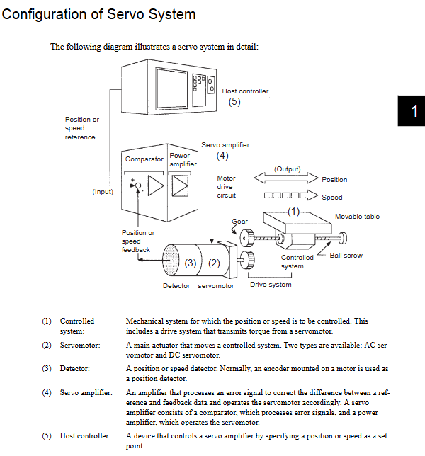
Servo System: A closed-loop control system that includes servo drives, upper level controllers, and peripheral devices.
Servo drive: a combination of servo motors and servo amplifiers.
Reverse signal: Add "/" before the name (such as/S-ON), it is effective when the low level is low.
Core Technical Characteristics
2.1 Core parameters of motor and amplifier
Category specific parameters
Servo motor type: synchronous type; Cooling method: Fan cooling (with built-in thermal protector); Braking options: 24V/90V DC brake (optional)
Servo amplifier control mode: P/PI control; Speed loop gain: 1-2000Hz; Position loop gain: adjustable through parameters; Integral time constant: 15-51200 × 0.01ms
Incremental encoder: 13 bit (2048P/R), 16 bit (16384P/R), 17 bit (32768P/R);
Absolute value: 17 bits (32768P/R), 20 bits (262144P/R, optional), supports multi turn limit setting
2.2 Core Functions
Control mode switching: Select position, speed, and torque control modes through parameter Pn000.1, and support mode switching (such as position → speed).
Electronic gear function: Set the gear ratio through Pn202 (numerator) and Pn203 (denominator), adapt to different mechanical transmission ratios, and the minimum reference unit can reach 1 μ m.
Autotuning: Automatically detects the rotational inertia and friction characteristics of the load, optimizes parameters such as speed loop gain (Pn100) and position loop gain (Pn102), and improves system response performance.
Protection functions: overtravel limit (P-OT/N-OT signal), torque limit (internal/external two-level limit), overcurrent protection, overheating protection, alarm reset (/ALM-RST).
Braking function: dynamic braking (DB), holding brake (applicable to vertical axis, preventing gravity from falling), zero clamp (locking the motor when stopped).
Installation and wiring specifications
3.1 Installation Requirements
Core requirements for installation objects
Indoor installation of servo motors, avoiding water and corrosive gases; Axis alignment error ≤ 0.03mm; the installation surface should be flat and the fixing screws should be tightened; The distance between the fan and the motor is ≥ 200mm
Vertical installation of servo amplifier DIN rail; The distance between adjacent devices is ≥ 10mm, and the distance between upper and lower devices is ≥ 50mm; the ambient temperature is 0-55 ℃, and there is no condensation or severe vibration (≤ 4.9m/s ²)
3.2 Wiring specifications
Main circuit wiring: The three-phase power supply (L1/R, L2/S, L3/T) is connected to the amplifier, and the motor power line (U/V/W) is correspondingly connected. The grounding resistance is ≤ 100 Ω, and the terminal screws must be tightened.
Control circuit wiring: CN1 (50 pins) is used for I/O signal interaction, including position pulses (PULS/IGN), servo enable (/S-ON), alarm output (ALM+/-), etc; The CN2 (encoder interface) uses shielded twisted pair cables, with a maximum length of 50m.
Brake wiring: Motors with brake pads need to be separately connected to a brake power supply (24V/90V DC), and the brake switch should be controlled through the/BK signal.
Noise control: The power line and signal line are arranged separately (with a spacing of ≥ 30cm), shielded cables are used, and noise filters are installed at the power end.
Parameter Configuration
4.1 Parameter Classification and Core Parameters
Parameter category represents parameter function description
Function selection parameters Pn000 Control mode selection (position/speed/torque), rotation direction selection
The servo gain parameter Pn100 speed loop gain (1-2000Hz) determines the speed response speed
Pn102 position loop gain, affecting positioning accuracy and stability
Position control parameters Pn202/Pn203 electronic gear ratio numerator/denominator, adapted to mechanical transmission ratio
Pn200 reference pulse form selection (symbol+pulse, two-phase 90 ° differential, etc.)
Speed control parameter Pn300 speed reference input gain (0.01V/rated speed)
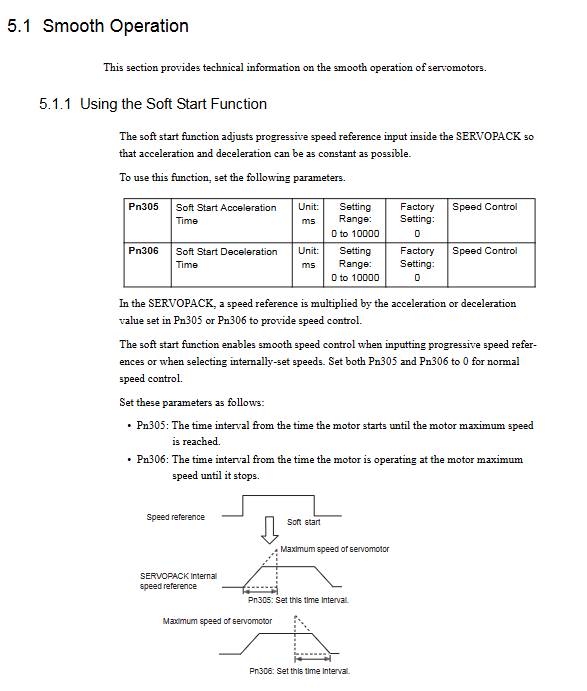
Pn305/Pn306 soft start acceleration/deceleration time (0-10000ms)
Torque control parameters Pn402/Pn403 forward/reverse torque limit (0-800% rated torque)
Pn400 torque reference input gain
Sequence parameters Pn50A-Pn512 I/O signal allocation and output signal inversion settings
4.2 Parameter Setting Process
Complete the wiring in a power-off state and confirm that the power, grounding, and encoder connections are correct;
Connect the power supply of the control circuit and enter the parameter setting mode through the digital operator;
Set core parameters (control mode, electronic gear ratio, servo gain, etc.) according to system requirements;
Power off and restart after changing parameters to make them effective;
Conduct a trial run and check the motor speed, torque, position error, and other status through monitoring mode (Un000-Un00D).
Trial operation process
Two step trial operation
No load trial operation:
Disconnect the mechanical connection between the motor and the load, and confirm that the P-OT/N-OT signal is short circuited;
Connect the power supply, start the jog (JOG) operation through the digital operator, and check whether the motor rotates smoothly and has no abnormal noise;
Monitor parameters such as speed (Un000) and current, and confirm that there are no alarms (ALM light off).
Test run with load:
Connect the motor to the load to ensure a secure mechanical installation;
Perform Autotuning to optimize servo gain parameters;
Send reference signals through the upper controller to test positioning accuracy, speed response, and load adaptability;
Verified the effectiveness of protection functions such as travel restrictions and emergency stops.
Maintenance and Troubleshooting
6.1 Daily Maintenance
Regular inspection: motor bearing wear, encoder cable integrity, amplifier heat dissipation, terminal screw tightness;
Battery replacement: The backup battery for the absolute value encoder (JZSP-BA01) needs to be replaced regularly to avoid loss of position data;
Cleaning requirements: Keep the equipment clean and avoid dust accumulation that affects heat dissipation.
6.2 Fault diagnosis
Alarm indication: Determine the fault type through the amplifier LED (ALM red light) and alarm codes (ALO1/ALO2/ALO3);
Common faults: overcurrent (A.01), overvoltage (A.02), encoder fault (A.81/A.82), overtravel (A.10);
Troubleshooting process: Power off and check wiring → Confirm parameter configuration → Test load status → Contact technical support (device serial number required).
Safety operation requirements
Grounding specifications: It must be reliably grounded (grounding resistance ≤ 100 Ω) to prevent electric shock or equipment damage;
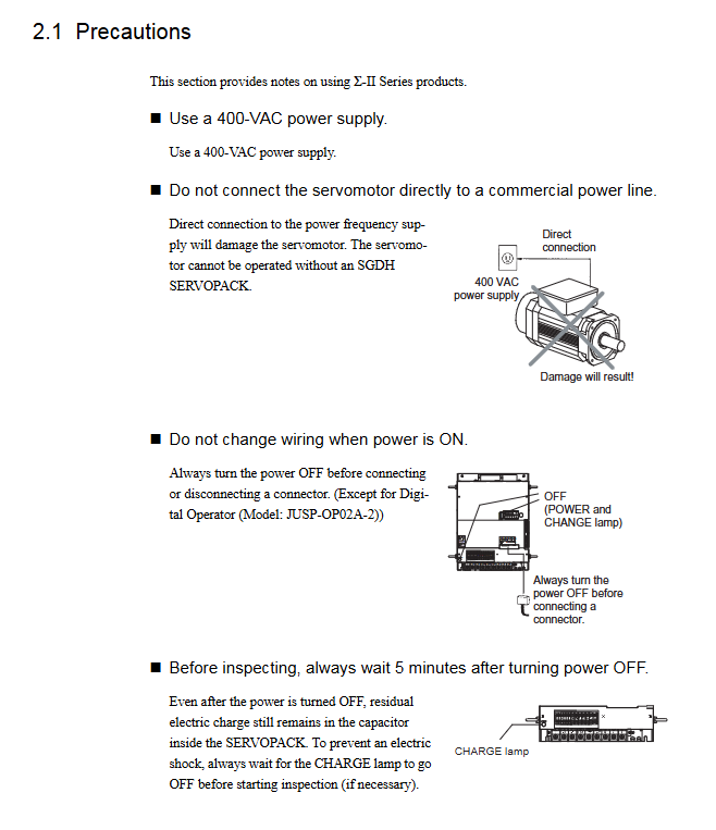
Power operation: Before wiring/disconnecting, the power must be cut off, and after the power is cut off, wait for 5 minutes (capacitor discharge) before touching the terminals;
Operating taboos: It is prohibited to directly connect the motor to a commercial power source; Do not touch rotating parts and heat sinks during operation; Unauthorized modification of parameters or disassembly of equipment is prohibited;
Emergency stop: The equipment needs to be equipped with an emergency stop button to ensure that the power can be quickly cut off in case of abnormalities.
- YOKOGAWA
- Reliance
- ADVANCED
- SEW
- ProSoft
- WATLOW
- Kongsberg
- FANUC
- VSD
- DCS
- PLC
- man-machine
- Covid-19
- Energy and Gender
- Energy Access
- Renewable Integration
- Energy Subsidies
- Energy and Water
- Net zero emission
- Energy Security
- Critical Minerals
- A-B
- petroleum
- Mine scale
- Sewage treatment
- cement
- architecture
- Industrial information
- New energy
- Automobile market
- electricity
- Construction site
- HIMA
- ABB
- Rockwell
- Schneider Modicon
- Siemens
- xYCOM
- Yaskawa
- Woodward
- BOSCH Rexroth
- MOOG
- General Electric
- American NI
- Rolls-Royce
- CTI
- Honeywell
- EMERSON
- MAN
- GE
- TRICONEX
- Control Wave
- ALSTOM
- AMAT
- STUDER
- KONGSBERG
- MOTOROLA
- DANAHER MOTION
- Bentley
- Galil
- EATON
- MOLEX
- Triconex
- DEIF
- B&W
- ZYGO
- Aerotech
- DANFOSS
- KOLLMORGEN
- Beijer
- Endress+Hauser
- schneider
- Foxboro
- KB
- REXROTH
- YAMAHA
- Johnson
- Westinghouse
- WAGO
- TOSHIBA
- TEKTRONIX
- BENDER
- BMCM
- SMC
- HITACHI
- HIRSCHMANN
- XP POWER
- Baldor
- Meggitt
- SHINKAWA
- Other Brands
- UniOP
- KUKA
- IBA
- Beckhoff
-
Basler Electric DECS-250-CN1SN1N Automatic Voltage Regulator for Generator Excitation Control
-
ADLINK CPCI-6860A - 51-31310-OB10 industrial motherboard CompactPCI SBC
-
ADLINK AmITX-SL-G-H110 - 51-7A104-0A30 Mini-ITX Industrial Motherboard
-
ADLINK PXI-2005-003 - CPCI Industrial PC Data Acquisition Card Multi-Function DAQ
-
ADLINK DININ-814M - 51-14032-0A3D SCSI-100P cable connection Interface Terminal Board
-
ADLINK CPCI-3920NA/C2D15/M1G - 3U CompactPCI Intel Core 2 Duo Single Board Computer
-
ADLINK PCIE-8560 - 51-18014-0A20 Communication Card High Speed DAQ
-
ADLINK PCI-C154+ - Motion Control Card 4-axis Motion Controller Board
-
ADLINK PCI-RTV24 - image capture card Analog Video Frame Grabber
-
ADLINK NuPRO-842LV/P - 51-41360-0B30 Industrial Motherboard CPU Board
-
ADLINK cBP-3208/3208R - CPCI Board 3U 8-Slot CompactPCI Backplane
-
ADLINK PCI-8164 - 4-Axis Motion Controller PCI Card 51-12406-0A40
-
ADLINK PCIe-GIE64+ - 4-CH GigE Vision PoE+ Frame Grabber Video Capture Card
-
ADLINK CPCI-6860 / 6860A - CompactPCI Dual Xeon Single Board Computer
-
ADLINK IEC-915GV - REV 1.1 Industrial motherboard CPU Board
-
ADLINK ND-6520 - Technology RS-232 to RS-422RS-485 Converter NuDAM Module
-
ADLINK RTV-24 / PCI-MP4S - 51-12519-1C30 4-Channel Real Time Video Capture Board
-
ADLINK cPCI-6910 / cPCI-6910AM/M1G - cPCI-6910AM/DXL16/M1G/S80G(G)-3120 BOARD CompactPCI SBC
-
ADLINK NUPRO-A40H - Linghua 51-41807-1A30 Industrial Control Computer Motherboard
-
ADLINK USB-3488A - USB to GPIB INTERFACE USB-3488A(G) Controller Module
-
ADLINK PCI-8134A - motion control card 4-Axis Controller Card
-
ADLINK PCI-7432 - Board 32-Channel input / 32-output Isolated Digital I/O PCI Card
-
ADLINK PCI-8134A - 51-12421-0A10 motion controller card tested
-
ADLINK LPCIe-7230 - 32 CH Isolated Input/output Card 2 Interrupts Low Profile PCIe
-
ADLINK NuPRO-E340 - industrial computer motherboard 51-47807-0A30 PICMG 1.3 SHB
-
ADLINK PCI-7434 - High-speed Digital Acquisition Card 64-CH Isolated DO Card
-
ADLINK NuPRO-E330 - 51-41805-0A20 Indsutrial Board SHB Single Board Computer
-
ADLINK PCI-7248 - OPTO-22 48 CHANNEL DIO DIGITAL TTL/DTL I/O 51-12006-0A40 GP
-
ADLINK PCI-8134 - Motion control card 4-Axis Controller Card
-
ADLINK AMP-208C - Movimiento Control Tarjeta 51-12420-1A20 W/Expansión & Breakout
-
ADLINK PCI-8164 - 51-12406-0A40 PCB Board 4-Axis Motion Controller Card
-
ADLINK DIN-68Y-SGII / DIN-68M-J3A - Terminal Board Connector Interface Block
-
ADLINK PCIe-7432 - Technology 51-18402-0A10 PCIe Card With High Input Range
-
ADLINK PCI-8144 / PCI-8144N - Motion control card 4-Axis Stepper Controller Card
-
ADLINK HSL-HUB3/REPEATER - HIGH SPEED LINK EXTENSION MODULES Distributed Hub Module
-
ADLINK ND-6017 - Data Logging + Acquisition 8CH A/D input Mod NuDAM Module
-
ADLINK LPCIe-7250 - data acquisition card Low Profile 8-CH Relay Output Card
-
ADLINK PCI-7432 - I/O card 64-CH Isolated Digital Input Output PCI Card
-
ADLINK IMB-M43H - industrial control computer motherboard Q87 Chip Micro-ATX
-
ADLINK MP-C154 - Motion control Card 4-Axis Motion Controller Board
-
ADLINK PCI-RTV24 - image capture card Video Frame Grabber Card
-
ADLINK PCI-7250 - 8-CH Relay Output & 8-CH Isolated DI Card
-
ADLINK PCI-6308V - 8-CH 12-Bit Isolated Analog Output PCI Card PCB-I-E-1148=6EX2
-
ADLINK PCI-7248 - capture card 48-CH Opto-22 Compatible DIO Card
-
ADLINK HSL-AI16A02-M-VV - Analog Input Output Distributed Module
-
ADLINK NuPRO-A301 - Rev:1.4 NUPRO-A301 PICMG Full-Size Single Board Computer
-
ADLINK PCI-6208V-GL - 8-CH Voltage Analog Output PCI Card
-
ADLINK PCI-8134A - 51-12421-0A10 4-Axis Motion Controller Card
-
ADLINK MNET-S23 - TECHNOLOGY MNET S23 - SERVO DRIVER CONTROL MODULE
-
ADLINK M-342 - ATX I3 I5 I7 Q67 Industrial Motherboard
-
ADLINK NUPRO-780 - Industrial Motherboard CPU Board PICMG SBC
-
ADLINK MP-C154 / MP-C152 - 4-Axis Motion Control Card Pulse-Train Controller
-
ADLINK NuPRO-935A/LV10B0 - Motherboard 51-41802-0A10 GP w/RAM Industrial Control Board
-
ADLINK MP-C154 - Motion control card 4-Axis Motion Controller Mainboard
-
ADLINK PCI-7250 - PCI Acquisition Card 8-CH Relay Output Isolated DI Card
-
ADLINK ACL-7124 - Technology Inc.24 DIO Card Digital Input Output Card
-
ADLINK PCI-8554 A2 - Timer/Counter Data Acquisition Card
-
ADLINK DIN-825-GP4 - Terminal Block Interface Board Breakout Module
-
ADLINK NuPR0-761 - REV:1.1 Industrial motherboard Full-Size PICMG SBC
-
ADLINK MXE-1401/M8G (G) - Matrix Fanless Embedded Computer Industrial PC
-
ADLINK HSL-DI16DO16-UD-NN - Digital 16 Channel I/O Mod Distributed I/O Module
-
ADLINK ND6520 - NUDAM INTELLIGENT DA&C MODULE RS232-RS-422/RS485 CONVERTOR
-
ADLINK NUPRO-761 - REV:1.1 Industrial Motherboard CPU Board
-
ADLINK AMP-208C - Motion Control Card 51-12420-1A20 DSP-based 8-axis
-
ADLINK NuPRO-A301REV 1.4 - with packaging industrial computer motherboard PICMG SBC
-
ADLINK PCM-9112+ - 51-12300-0A2 industrial motherboard Multi-Function DAQ PC/104 Module
-
ADLINK PCM-7250+ - 8-CH Relay Outputs & 8-CH Isolated DI Module PC/104
-
ADLINK PCI-RTV24 - Image capture card Analog Video Frame Grabber
-
ADLINK PCI-8134 - Motion Controller PCI Card 4-Axis Controller Board
-
ADLINK PCI-7432 - Isolated Digital I/O PCI Card
-
ADLINK PCI-8554 A2 - acquisition card Timer/Counter Card
-
ADLINK PCI-8132 - Rev.A2 2-Axis Servo & Stepper Motion Controller Card
-
ADLINK PCI-8132 - Data Acquisition card 2-Axis Motion Controller Card
-
ADLINK EBP-13E4 - 51-46703-0A30 Industrial Backplane Board Passive Backplane
-
ADLINK PCI-800L - Electronic Card Interface Controller Card
-
ADLINK PCIe-GIE72 - 51-18531-0A10 PCB Board GigE Vision Frame Grabber
-
ADLINK DAQ-2010(G)-OOBO - Simultaneous-Sampling Multi-Function DAQ Card
-
ADLINK PCI-9112 - REV.B1 Multifunction DAQ Card Data Acquisition Card
-
ADLINK PCI-7230 - 51-12003-DA60 32-CH Isolated Digital I/O Card
-
ADLINK PCI-7432 - Data Acquisition Card Isolated Digital I/O PCI Card
-
ADLINK ETX-AT-N270-18/LXE - 51-71111-0A20 ETX CPU Module Motherboard
-
ADLINK HSL-DI32-UD-N - DIGITAL INPUT 32 POINTS MODULE Distributed I/O
-
ADLINK AMP-204C - Motion Control card DSP-Based 4-Axis Advanced Controller
-
ADLINK MNET-4XMOG-0050 - Four-axis Motion Controller Distributed Motion Module
-
ADLINK AMP-204C - Motion control card DSP-Based 4-Axis Pulse-Train Controller
-
ADLINK PCI-7442 - Switch card 64-Channel Datalogging & Acquisition Card
-
ADLINK M-302 - Industrial control motherboard ATX PC Board
-
ADLINK NUPRO-852 / NUPRO-852LV - Industrial motherboard Single Board Computer
-
ADLINK PCI-8134 - REV.B1. 4-Axis Motion Controller Card
-
ADLINK PCI-GIE62 + - 51-18502-0A20 2-CH GigE Vision Frame Grabber PoE Card
-
ADLINK PCI-MPG24 - 51-12523-0B20 MPEG4 Card Video Compression Hardware
-
ADLINK HSL-TB32-M-DIN - 32-CH I/O TERMINAL W/ HSL-AI16AO2-M-VV MODULE
-
ADLINK PCI-M114-GL - PCB Ver 2.1 Motion Controller Axis Card
-
ADLINK IMB-M40H - SYM76996H61 motherboard Industrial Computer Mainboard
-
ADLINK NUPRO-A40H - 51-41807-1A20 industrial control motherboard H61 Chip
-
ADLINK PCI-M114-GL - Axis Card Data Acquisition Card PCB VER2.2 Motion Controller
-
ADLINK PCI-8134 - Motion Controller PCI Card 4-Axis Controller Board
-
ADLINK PCI-8102 - Motion control card 2-Axis Servo & Stepper Controller
-
ADLINK NuPRO-841REV:3.0 - motherboard Industrial Control PC Board
-
ADLINK HSL-TB32-U-DIN REV A1 - Breakout Terminal Board Field I/O Module
-
ADLINK AMP-204C - Motion Control card DSP-Based 4-Axis Pulse-Train Controller
-
ADLINK NUPRO-A40H - 51-41807-1A20 industrial control motherboard H61 PC Board
-
ADLINK PCI-6308A / PCI-6308V - 51-12202-0A50 Isolated Analog Output Card
-
ADLINK AMP-204C - DSP-Based 4-Axis Advanced Pulse-Train Motion Controller
-
ADLINK PCI-7434 - Technology 64-Channel Isolated Digital I/O PCI Cards
-
ADLINK CPCI-6840 / CPCI-6840V / PM16/M1G-12G0 - CompactPCI Single Board Computer CPU Module
-
ADLINK PCIE-GIE74 - Motherboard Video Capture Card 51-18531-0A10 Frame Grabber
-
ADLINK NuPRO-E330 - industrial computer equipment motherboard Control Mainboard
-
ADLINK AMP-208C / 51-12420-1A20 - Motion Control Card W/ Expansion & Breakout Board
-
ADLINK HPCI-14S12U - industrial computer baseboard Passive Backplane 14 Slots
-
ADLINK PCI-8164 - 4-Axis Motion Controller PCI Card W/ 1x Cable, 1x Breakout Box
-
ADLINK PCIe-RTV24 - 51-18016-0A20 Image Acquisition Video Capture Card
-
ADLINK M-342 - 5 PCI ATX Motherboard Industrial PC Mainboard
-
ADLINK PCI-FIW64 - 4/2 Channel IEEE1394B Image Capture Card FireWire Frame Grabber
-
ADLINK PCI-7432 - digital IO card 64-CH Isolated Digital Input Output Card
-
ADLINK 51-12001-0C20 - Circuit Board PCI-7200 Data Acquisition Controller Card
-
ADLINK PXI-3920 - PXI 3U cPCI Industrial Controller Embedded System CPU Board
-
ADLINK NuPRO-841REV:2.0 - motherboard Industrial Control PC Board
-
ADLINK NuPro-E330 - 51-41805-0A20 PCB Industrial Control Computer Motherboard
-
ADLINK PCI-RTV24 - Image capture card Analog Video Frame Grabber
-
ADLINK PCI-7442 - Switch card 64-Channel Datalogging & Acquisition Card
-
ADLINK HPX-13S4 - device baseboard Passive Backplane Riser Card
-
ADLINK PCI-9112 REV A.1 - Multi Function DA&C Board Data Acquisition Card
-
ADLINK PCI-7248 - 51-12006-0A40 Card Control 48-CH Digital I/O Module
-
ADLINK CPCI-6860 / 6860A - motherboard CompactPCI Dual Xeon Single Board Computer
-
ADLINK DPAC-3020-11(G) - Embedded PC Automation Controller Machine Control Board
-
ADLINK NuPRO-841 REV:1.0 - industrial control motherboard CPU Board
-
ADLINK MNET-4XMOG-0050 - Four-axis Motion Controller MNET Motion Control Card

K-JIANG

Add: Jimei North Road, Jimei District, Xiamen, Fujian, China
Tell:+86-15305925923