
K-WANG


KONGSBERG RMP420 Remote Multi functional I/O Module
Industrial application and technical advantages of KONGSBERG GT300 pressure transmitter
Chapter 1: Product Overview and Application Positioning
1.1 Precise positioning of universal design
The GT300 pressure transmitter is defined as a general purpose transmitter, primarily designed for engine rooms, hydraulic stations, and similar industrial applications. It offers two forms of gauge pressure and sealed gauge pressure, covering a wide range of needs from micro pressure to high pressure.
1.2 Range and Output
This series supports a pressure range of up to 100 bar and adopts the industry standard 2-wire connection method, with output signals ranging from 4 to 20mA analog. This signal system has strong anti-interference ability and is suitable for long-distance transmission, making it a classic choice for industrial sites. Its nominal power supply value is 24 VDC, allowing for fluctuations within a wide voltage range of 12 to 32 VDC, greatly facilitating compatibility with different ship or factory power supply systems.
Chapter 2: Core Technology Innovation: Dry Ceramic Sensors
The most significant technical feature of the GT300 is its pressure sensitive element - a dry measurement unit made of 96% alumina (Al ₂ O3) ceramic.
2.1 Material advantage: 96% alumina ceramic
Alumina ceramics are widely recognized as highly elastic, corrosion-resistant, and wear-resistant materials. The GT300 uses 96% pure ceramic film, which has extremely high chemical inertness and can withstand the corrosion of most chemical media. This means that the measured process medium can directly contact the measuring diaphragm, without the need to transmit pressure through stainless steel isolation diaphragm and intermediate filling liquid (such as silicone oil) like traditional sensors.
2.2 Technical differentiation between wet and dry methods
In traditional "wet" sensors, the filling fluid is both a pressure transmission medium and a potential source of error. When the ambient temperature changes, the thermal expansion and contraction of the filling liquid will cause a volume change, thereby introducing temperature drift errors. In addition, if the isolation membrane is damaged and the filling liquid leaks, it will cause the sensor to completely fail. The "dry" design of GT300 fundamentally eliminates these issues, which explains why it can surpass traditional analog sensors in temperature stability indicators.
2.3 Signal Conversion and Digital Compensation
The internal core of GT300 is a rigid structure composed of ceramic membrane and insulating substrate. Strain gauges connected in the form of Wheatstone bridges are integrated on the membrane. When pressure is applied, the small deformation of the diaphragm causes a change in the resistance value of the strain gauge, which is converted into an electrical signal.
The revolutionary breakthrough of GT300 lies in its digital compensation process:
Individualized calibration: Each sensor undergoes dual scanning of pressure and temperature during the manufacturing process.
Table lookup compensation: The collected data is digitized and stored in the built-in memory of the sensor, forming a unique 'Tabular'.
Real time calibration: During operation, the microprocessor combines real-time temperature and pressure signals to perform linearization and temperature compensation calculations based on this table.
This digital compensation technology based on the unique characteristics of each component enables the GT300 to achieve accuracy and stability far ahead of analog sensors in the compensation temperature range of 0 to 60 ° C, ultimately ensuring a full-scale output accuracy (FRO) of 0.5%.
Chapter 3: Mechanical Structure and Material Technology
3.1 Shell and Protection
The main structure of GT300 is made of AISI 316L stainless steel. 316L is a low-carbon, molybdenum containing austenitic stainless steel with excellent resistance to intergranular corrosion, especially chloride ion corrosion, making it very suitable for ships and offshore environments. Its protection level reaches IP56, which means it can prevent dust (dust level 5, no harmful deposits) and strong water spray, sufficient to cope with the flushing and humid environment inside the cabin.
3.2 Pressure and Electrical Interface
Pressure interface: The pressure connection located at the lower end of the transmitter complies with the ISO228 standard and mainly provides two specifications of cylindrical threads, G1/2A and G1/4A. These threads are usually sealed with sealing gaskets (such as Viton seals provided with the goods).
Electrical interface: The upper end adopts a connector that complies with DIN 175301-803 standard. This type of connector is commonly known as the "Hirschman connector" or "square plug" in the industrial field, with convenient and reliable wiring. Users can choose the appropriate cable gland based on the outer diameter of the cable, such as M16 or M20 specifications.
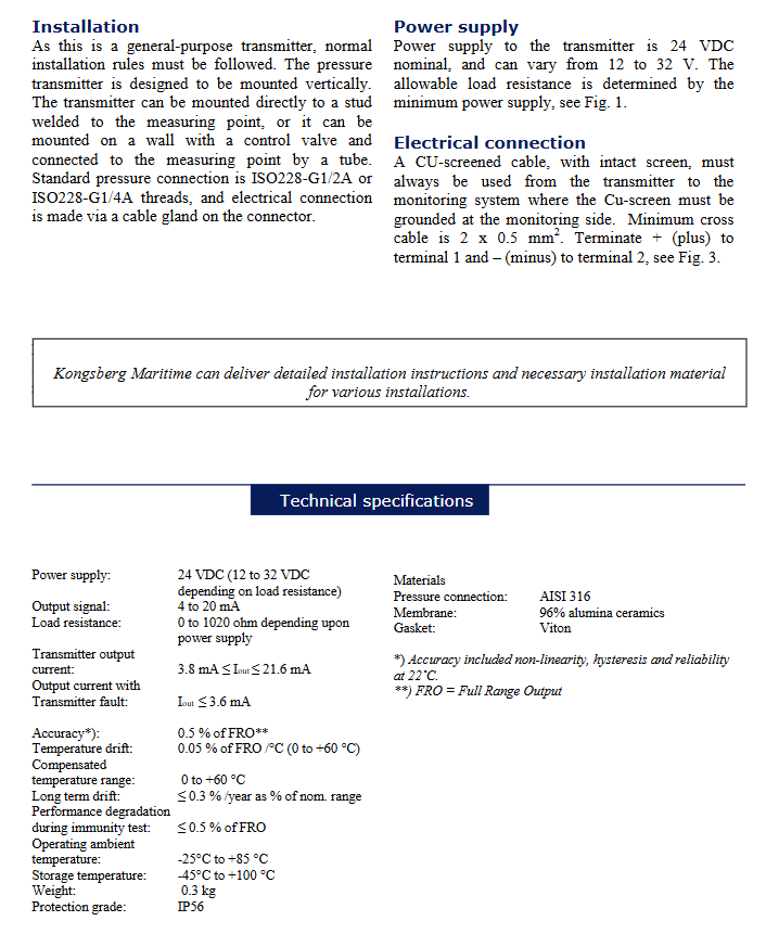
Chapter 4: Electrical Characteristics and Installation Specifications
4.1 Power Supply and Load Capacity
The electrical design of GT300 follows the principle of two-wire circuit power supply. The load resistance capability depends on the magnitude of the supply voltage. As shown in Figure 1 (original Fig.1 in the manual), the allowable load resistance is proportional to the power supply voltage. For example, when powered by 24V, it can drive loads up to about 600 Ω (excluding the minimum operating voltage of the transmitter itself), making it easy to work with PLC analog input modules or digital display instruments.
4.2 Wiring Details
When wiring, attention must be paid to polarity and shielding layer handling:
Terminal definition: Terminal 1 is connected to the positive pole (+) of the power supply, and terminal 2 is connected to the negative pole (-) of the signal output.
Cable requirements: Copper screened cable with shielding layer must be used, and the cable cross-sectional area is recommended to be no less than 2 x 0.5 mm ².
Grounding principle: In order to prevent electromagnetic interference (EMI) from affecting the measurement signal, the shielding layer must be single ended grounded on the monitoring system side (i.e. PLC or control cabinet side).
4.3 Fault safety logic
GT300 has a fault self diagnosis function. When there is a malfunction inside the sensor (such as component damage or disconnection), the output current will drop below 3.6mA or rise above 22mA. This "transmitter fault current" mechanism helps the control system identify sensor abnormalities and avoid misoperations caused by incorrect readings.
Chapter 5: Installation Practice and Precautions
Although the GT300 is designed to be sturdy and durable, proper installation is a prerequisite for unleashing its performance.
5.1 Installation direction
The manufacturer recommends installing vertically. This is not only beneficial for mechanical stability, but also reduces zero offset caused by the self weight of the membrane or the deposition of small particles in the medium.
5.2 Installation method
Direct installation: It can be welded directly onto the base of the measuring point through bolts.
Remote installation: Introduce pressure into the transmitter through a pressure conduit. For steam or high-temperature media, the pressure pipe can also play a role in heat dissipation and buffering, preventing high temperatures from directly impacting the sensor electronic unit.
5.3 Environmental Requirements
Despite having IP56 protection, the electronic part of the sensor should be avoided from being exposed to severe thermal radiation or strong electromagnetic interference sources during long-term use. If the temperature of the measured medium changes dramatically, damping or buffering devices can be added within the allowable range of the process.
Chapter 6: Selection Guide and Order Code Interpretation
Understanding the ordering code of GT300 is crucial for proper procurement. According to the "Ordering key" on page four of the manual, we can deconstruct it as follows:
Model example: GT300 C 0 0 C G 1 0 G 0 E05 XXX
GT300: Basic series number.
Pressure Connection:
V=G1/2A, AISI 316L material, Viton seal.
B=G1/4A, AISI 316L material, Viton seal.
OUTPUT SIGNAL:
0 = 4-20mA, Second line system.
Application:
0=General/engine compartment.
Accuracy:
C=0.5% accuracy, temperature compensation range 0-60 ° C.
ZERO POINT:
G=4mA corresponds to atmospheric pressure (zero point of gauge pressure).
K=4mA corresponds to -1 bar gauge (for vacuum or negative pressure measurement).
RANGE AND OVERLOAD PRESSURE:
This is a combination code, for example, 10 corresponds to a range of 0-10 bar and overload of 20 bar; 60 corresponds to a range of 0-60bar, overload of 100bar, etc.
CABLE GLAND:
1=M16 (applicable for cable diameters of 3.5-8mm)
2=M16 * (applicable cable diameter 6-10mm)
3=M20 (applicable cable diameter 7-13mm)
CABLE (cable option):
E05=with 5-meter cable (EFTE oil resistant material)
E10=with 10 meter cable
XXX=Special Customization
Chapter 7: Performance Comparison and Industry Development Trends
7.1 Ceramic Sensor vs. Diffuse Silicon Sensor
In the field of industrial pressure measurement, diffusion silicon sensors and ceramic sensors are the two mainstream technologies. The diffusion silicon sensor has extremely high sensitivity and is suitable for micro pressure measurement, but its PN junction is easily affected in high temperature environments and must rely on a filling liquid isolation medium. Although ceramic sensors (such as those used in GT300) have slightly lower sensitivity than silicon, their characteristics of no hysteresis, overload resistance, and corrosion resistance make them have a longer service life and stability under harsh working conditions. The 0.5% accuracy of GT300 is considered excellent in the general industrial field, while its long-term drift is controlled at an extremely low level through digital compensation.
7.2 Overload resistance capability
Overload is the main cause of sensor damage. The elastic limit of ceramic materials is extremely high. When the pressure instantly exceeds the range or even reaches several times the overload, the ceramic diaphragm will adhere tightly to the substrate (bottom) instead of undergoing plastic deformation like metal diaphragms. Once the pressure returns to normal, the sensor immediately resumes operation with unchanged performance. The GT300 provides clear overload pressure indicators for different ranges, such as a 0.6bar range that can withstand an overload of 2bar, and a 10bar range that can withstand an overload of 20bar.
Chapter 8: Maintenance and Troubleshooting
In practical applications, GT300 may experience output abnormalities, which can usually be attributed to the following reasons:
Blockage of the pressure system: Sediments or crystals at the process connection block the pressure channel.
Wiring and grounding: The shielding layer is not properly grounded or the cable is laid in parallel with the power cable, which introduces interference.
Sealing failure: The aging or improper installation of Viton sealing rings leads to medium leakage.
Exceeding compensation temperature: Although the storage temperature range is wide, if electronic components work at 85 ° C or above for a long time, it will accelerate component aging.
It is recommended that users perform regular zero calibration (adjust under no pressure) and check whether the cable joints are loose or have water ingress.
- YOKOGAWA
- Reliance
- ADVANCED
- SEW
- ProSoft
- WATLOW
- Kongsberg
- FANUC
- VSD
- DCS
- PLC
- man-machine
- Covid-19
- Energy and Gender
- Energy Access
- Renewable Integration
- Energy Subsidies
- Energy and Water
- Net zero emission
- Energy Security
- Critical Minerals
- A-B
- petroleum
- Mine scale
- Sewage treatment
- cement
- architecture
- Industrial information
- New energy
- Automobile market
- electricity
- Construction site
- HIMA
- ABB
- Rockwell
- Schneider Modicon
- Siemens
- xYCOM
- Yaskawa
- Woodward
- BOSCH Rexroth
- MOOG
- General Electric
- American NI
- Rolls-Royce
- CTI
- Honeywell
- EMERSON
- MAN
- GE
- TRICONEX
- Control Wave
- ALSTOM
- AMAT
- STUDER
- KONGSBERG
- MOTOROLA
- DANAHER MOTION
- Bentley
- Galil
- EATON
- MOLEX
- Triconex
- DEIF
- B&W
- ZYGO
- Aerotech
- DANFOSS
- KOLLMORGEN
- Beijer
- Endress+Hauser
- schneider
- Foxboro
- KB
- REXROTH
- YAMAHA
- Johnson
- Westinghouse
- WAGO
- TOSHIBA
- TEKTRONIX
- BENDER
- BMCM
- SMC
- HITACHI
- HIRSCHMANN
- XP POWER
- Baldor
- Meggitt
- SHINKAWA
- Other Brands
- UniOP
- KUKA
- IBA
- Beckhoff
-
Basler Electric DECS-250-CN1SN1N Automatic Voltage Regulator for Generator Excitation Control
-
ADLINK CPCI-6860A - 51-31310-OB10 industrial motherboard CompactPCI SBC
-
ADLINK AmITX-SL-G-H110 - 51-7A104-0A30 Mini-ITX Industrial Motherboard
-
ADLINK PXI-2005-003 - CPCI Industrial PC Data Acquisition Card Multi-Function DAQ
-
ADLINK DININ-814M - 51-14032-0A3D SCSI-100P cable connection Interface Terminal Board
-
ADLINK CPCI-3920NA/C2D15/M1G - 3U CompactPCI Intel Core 2 Duo Single Board Computer
-
ADLINK PCIE-8560 - 51-18014-0A20 Communication Card High Speed DAQ
-
ADLINK PCI-C154+ - Motion Control Card 4-axis Motion Controller Board
-
ADLINK PCI-RTV24 - image capture card Analog Video Frame Grabber
-
ADLINK NuPRO-842LV/P - 51-41360-0B30 Industrial Motherboard CPU Board
-
ADLINK cBP-3208/3208R - CPCI Board 3U 8-Slot CompactPCI Backplane
-
ADLINK PCI-8164 - 4-Axis Motion Controller PCI Card 51-12406-0A40
-
ADLINK PCIe-GIE64+ - 4-CH GigE Vision PoE+ Frame Grabber Video Capture Card
-
ADLINK CPCI-6860 / 6860A - CompactPCI Dual Xeon Single Board Computer
-
ADLINK IEC-915GV - REV 1.1 Industrial motherboard CPU Board
-
ADLINK ND-6520 - Technology RS-232 to RS-422RS-485 Converter NuDAM Module
-
ADLINK RTV-24 / PCI-MP4S - 51-12519-1C30 4-Channel Real Time Video Capture Board
-
ADLINK cPCI-6910 / cPCI-6910AM/M1G - cPCI-6910AM/DXL16/M1G/S80G(G)-3120 BOARD CompactPCI SBC
-
ADLINK NUPRO-A40H - Linghua 51-41807-1A30 Industrial Control Computer Motherboard
-
ADLINK USB-3488A - USB to GPIB INTERFACE USB-3488A(G) Controller Module
-
ADLINK PCI-8134A - motion control card 4-Axis Controller Card
-
ADLINK PCI-7432 - Board 32-Channel input / 32-output Isolated Digital I/O PCI Card
-
ADLINK PCI-8134A - 51-12421-0A10 motion controller card tested
-
ADLINK LPCIe-7230 - 32 CH Isolated Input/output Card 2 Interrupts Low Profile PCIe
-
ADLINK NuPRO-E340 - industrial computer motherboard 51-47807-0A30 PICMG 1.3 SHB
-
ADLINK PCI-7434 - High-speed Digital Acquisition Card 64-CH Isolated DO Card
-
ADLINK NuPRO-E330 - 51-41805-0A20 Indsutrial Board SHB Single Board Computer
-
ADLINK PCI-7248 - OPTO-22 48 CHANNEL DIO DIGITAL TTL/DTL I/O 51-12006-0A40 GP
-
ADLINK PCI-8134 - Motion control card 4-Axis Controller Card
-
ADLINK AMP-208C - Movimiento Control Tarjeta 51-12420-1A20 W/Expansión & Breakout
-
ADLINK PCI-8164 - 51-12406-0A40 PCB Board 4-Axis Motion Controller Card
-
ADLINK DIN-68Y-SGII / DIN-68M-J3A - Terminal Board Connector Interface Block
-
ADLINK PCIe-7432 - Technology 51-18402-0A10 PCIe Card With High Input Range
-
ADLINK PCI-8144 / PCI-8144N - Motion control card 4-Axis Stepper Controller Card
-
ADLINK HSL-HUB3/REPEATER - HIGH SPEED LINK EXTENSION MODULES Distributed Hub Module
-
ADLINK ND-6017 - Data Logging + Acquisition 8CH A/D input Mod NuDAM Module
-
ADLINK LPCIe-7250 - data acquisition card Low Profile 8-CH Relay Output Card
-
ADLINK PCI-7432 - I/O card 64-CH Isolated Digital Input Output PCI Card
-
ADLINK IMB-M43H - industrial control computer motherboard Q87 Chip Micro-ATX
-
ADLINK MP-C154 - Motion control Card 4-Axis Motion Controller Board
-
ADLINK PCI-RTV24 - image capture card Video Frame Grabber Card
-
ADLINK PCI-7250 - 8-CH Relay Output & 8-CH Isolated DI Card
-
ADLINK PCI-6308V - 8-CH 12-Bit Isolated Analog Output PCI Card PCB-I-E-1148=6EX2
-
ADLINK PCI-7248 - capture card 48-CH Opto-22 Compatible DIO Card
-
ADLINK HSL-AI16A02-M-VV - Analog Input Output Distributed Module
-
ADLINK NuPRO-A301 - Rev:1.4 NUPRO-A301 PICMG Full-Size Single Board Computer
-
ADLINK PCI-6208V-GL - 8-CH Voltage Analog Output PCI Card
-
ADLINK PCI-8134A - 51-12421-0A10 4-Axis Motion Controller Card
-
ADLINK MNET-S23 - TECHNOLOGY MNET S23 - SERVO DRIVER CONTROL MODULE
-
ADLINK M-342 - ATX I3 I5 I7 Q67 Industrial Motherboard
-
ADLINK NUPRO-780 - Industrial Motherboard CPU Board PICMG SBC
-
ADLINK MP-C154 / MP-C152 - 4-Axis Motion Control Card Pulse-Train Controller
-
ADLINK NuPRO-935A/LV10B0 - Motherboard 51-41802-0A10 GP w/RAM Industrial Control Board
-
ADLINK MP-C154 - Motion control card 4-Axis Motion Controller Mainboard
-
ADLINK PCI-7250 - PCI Acquisition Card 8-CH Relay Output Isolated DI Card
-
ADLINK ACL-7124 - Technology Inc.24 DIO Card Digital Input Output Card
-
ADLINK PCI-8554 A2 - Timer/Counter Data Acquisition Card
-
ADLINK DIN-825-GP4 - Terminal Block Interface Board Breakout Module
-
ADLINK NuPR0-761 - REV:1.1 Industrial motherboard Full-Size PICMG SBC
-
ADLINK MXE-1401/M8G (G) - Matrix Fanless Embedded Computer Industrial PC
-
ADLINK HSL-DI16DO16-UD-NN - Digital 16 Channel I/O Mod Distributed I/O Module
-
ADLINK ND6520 - NUDAM INTELLIGENT DA&C MODULE RS232-RS-422/RS485 CONVERTOR
-
ADLINK NUPRO-761 - REV:1.1 Industrial Motherboard CPU Board
-
ADLINK AMP-208C - Motion Control Card 51-12420-1A20 DSP-based 8-axis
-
ADLINK NuPRO-A301REV 1.4 - with packaging industrial computer motherboard PICMG SBC
-
ADLINK PCM-9112+ - 51-12300-0A2 industrial motherboard Multi-Function DAQ PC/104 Module
-
ADLINK PCM-7250+ - 8-CH Relay Outputs & 8-CH Isolated DI Module PC/104
-
ADLINK PCI-RTV24 - Image capture card Analog Video Frame Grabber
-
ADLINK PCI-8134 - Motion Controller PCI Card 4-Axis Controller Board
-
ADLINK PCI-7432 - Isolated Digital I/O PCI Card
-
ADLINK PCI-8554 A2 - acquisition card Timer/Counter Card
-
ADLINK PCI-8132 - Rev.A2 2-Axis Servo & Stepper Motion Controller Card
-
ADLINK PCI-8132 - Data Acquisition card 2-Axis Motion Controller Card
-
ADLINK EBP-13E4 - 51-46703-0A30 Industrial Backplane Board Passive Backplane
-
ADLINK PCI-800L - Electronic Card Interface Controller Card
-
ADLINK PCIe-GIE72 - 51-18531-0A10 PCB Board GigE Vision Frame Grabber
-
ADLINK DAQ-2010(G)-OOBO - Simultaneous-Sampling Multi-Function DAQ Card
-
ADLINK PCI-9112 - REV.B1 Multifunction DAQ Card Data Acquisition Card
-
ADLINK PCI-7230 - 51-12003-DA60 32-CH Isolated Digital I/O Card
-
ADLINK PCI-7432 - Data Acquisition Card Isolated Digital I/O PCI Card
-
ADLINK ETX-AT-N270-18/LXE - 51-71111-0A20 ETX CPU Module Motherboard
-
ADLINK HSL-DI32-UD-N - DIGITAL INPUT 32 POINTS MODULE Distributed I/O
-
ADLINK AMP-204C - Motion Control card DSP-Based 4-Axis Advanced Controller
-
ADLINK MNET-4XMOG-0050 - Four-axis Motion Controller Distributed Motion Module
-
ADLINK AMP-204C - Motion control card DSP-Based 4-Axis Pulse-Train Controller
-
ADLINK PCI-7442 - Switch card 64-Channel Datalogging & Acquisition Card
-
ADLINK M-302 - Industrial control motherboard ATX PC Board
-
ADLINK NUPRO-852 / NUPRO-852LV - Industrial motherboard Single Board Computer
-
ADLINK PCI-8134 - REV.B1. 4-Axis Motion Controller Card
-
ADLINK PCI-GIE62 + - 51-18502-0A20 2-CH GigE Vision Frame Grabber PoE Card
-
ADLINK PCI-MPG24 - 51-12523-0B20 MPEG4 Card Video Compression Hardware
-
ADLINK HSL-TB32-M-DIN - 32-CH I/O TERMINAL W/ HSL-AI16AO2-M-VV MODULE
-
ADLINK PCI-M114-GL - PCB Ver 2.1 Motion Controller Axis Card
-
ADLINK IMB-M40H - SYM76996H61 motherboard Industrial Computer Mainboard
-
ADLINK NUPRO-A40H - 51-41807-1A20 industrial control motherboard H61 Chip
-
ADLINK PCI-M114-GL - Axis Card Data Acquisition Card PCB VER2.2 Motion Controller
-
ADLINK PCI-8134 - Motion Controller PCI Card 4-Axis Controller Board
-
ADLINK PCI-8102 - Motion control card 2-Axis Servo & Stepper Controller
-
ADLINK NuPRO-841REV:3.0 - motherboard Industrial Control PC Board
-
ADLINK HSL-TB32-U-DIN REV A1 - Breakout Terminal Board Field I/O Module
-
ADLINK AMP-204C - Motion Control card DSP-Based 4-Axis Pulse-Train Controller
-
ADLINK NUPRO-A40H - 51-41807-1A20 industrial control motherboard H61 PC Board
-
ADLINK PCI-6308A / PCI-6308V - 51-12202-0A50 Isolated Analog Output Card
-
ADLINK AMP-204C - DSP-Based 4-Axis Advanced Pulse-Train Motion Controller
-
ADLINK PCI-7434 - Technology 64-Channel Isolated Digital I/O PCI Cards
-
ADLINK CPCI-6840 / CPCI-6840V / PM16/M1G-12G0 - CompactPCI Single Board Computer CPU Module
-
ADLINK PCIE-GIE74 - Motherboard Video Capture Card 51-18531-0A10 Frame Grabber
-
ADLINK NuPRO-E330 - industrial computer equipment motherboard Control Mainboard
-
ADLINK AMP-208C / 51-12420-1A20 - Motion Control Card W/ Expansion & Breakout Board
-
ADLINK HPCI-14S12U - industrial computer baseboard Passive Backplane 14 Slots
-
ADLINK PCI-8164 - 4-Axis Motion Controller PCI Card W/ 1x Cable, 1x Breakout Box
-
ADLINK PCIe-RTV24 - 51-18016-0A20 Image Acquisition Video Capture Card
-
ADLINK M-342 - 5 PCI ATX Motherboard Industrial PC Mainboard
-
ADLINK PCI-FIW64 - 4/2 Channel IEEE1394B Image Capture Card FireWire Frame Grabber
-
ADLINK PCI-7432 - digital IO card 64-CH Isolated Digital Input Output Card
-
ADLINK 51-12001-0C20 - Circuit Board PCI-7200 Data Acquisition Controller Card
-
ADLINK PXI-3920 - PXI 3U cPCI Industrial Controller Embedded System CPU Board
-
ADLINK NuPRO-841REV:2.0 - motherboard Industrial Control PC Board
-
ADLINK NuPro-E330 - 51-41805-0A20 PCB Industrial Control Computer Motherboard
-
ADLINK PCI-RTV24 - Image capture card Analog Video Frame Grabber
-
ADLINK PCI-7442 - Switch card 64-Channel Datalogging & Acquisition Card
-
ADLINK HPX-13S4 - device baseboard Passive Backplane Riser Card
-
ADLINK PCI-9112 REV A.1 - Multi Function DA&C Board Data Acquisition Card
-
ADLINK PCI-7248 - 51-12006-0A40 Card Control 48-CH Digital I/O Module
-
ADLINK CPCI-6860 / 6860A - motherboard CompactPCI Dual Xeon Single Board Computer
-
ADLINK DPAC-3020-11(G) - Embedded PC Automation Controller Machine Control Board
-
ADLINK NuPRO-841 REV:1.0 - industrial control motherboard CPU Board
-
ADLINK MNET-4XMOG-0050 - Four-axis Motion Controller MNET Motion Control Card

K-JIANG

Add: Jimei North Road, Jimei District, Xiamen, Fujian, China
Tell:+86-15305925923